
Niris
Walter E. Damuck, Jr.
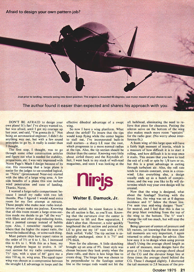
DON'T BE AFRAID to design your own plane! It's fun! I've always wanted to, but was afraid, until I got my courage up last year, and said, "I'm gonna do it." Not being an aeronautical engineer, I didn't do anything way out, but with a few sound principles to go by, it really is easier than I thought.
The first step, I thought, was to go through some other construction articles and figure out what is needed for stability, proportions, etc. I was very impressed with Norm Page's Mach I design because of its size. His reasoning that a large plane is easier for the judges to see sounded logical, so "Niris" (pronounced Near-iss) started with the idea of a large wing area. A few side benefits of a plane this size include wind penetration and ease of landing. Thanks, Norm.
I wanted a large radio compartment because I install my radio with two left thumbs. Plus I figured I would need extra room for my first attempt at retracts. Those people who make neat radio installations always make me jealous. Knowing that all this room meant a large cross-section made me decide to go "all the way" with fillets and other drag-reducing items like a painted canopy instead of bubble type. Also, I remember reading somewhere that the higher the aspect ratio, the lower the induced drag, or some such thing. Most pattern ships have aspect ratios in the order of 5 1/2 or 6 to 1, so I increased this to 6 1/2 to 1. With this as a base, my wing planform began to evolve. A 14" root section for my radio compartment, 7 1/2" tips, span 66" gave a nice 710 sq. in. wing area. The equal taper wing was chosen as a compromise between the straight LE advantage in loops and the effective dihedral advantage of a swept wing.
So now I have a wing planform. What about the airfoil? To insure that the tips would keep flying while the center begins to stall out, I've incorporated built-in stall starters — a sharp LE near the root, which progresses to a more normal radius at the tips. Also, the tip section should be thicker than the center. Knowing very little about airfoil theory and the Reynolds effect, I went back to my stack of well-read magazines, and soon I was looking at the Banshee airfoil. Its nicest feature is that the aft section is flat, as you'll see. Knowing that the curvature over the center is important to lift and flow separation, I didn't alter that. However, a ruler quickly lengthened the aft section and pointed the LE to give me my 14" root with a 15% thick airfoil. Voila! The tip section is essentially unchanged, since it is 7 3/4" and 17% thick.
Now for the ailerons. A little sketching brought up an area of 9%. Inset style was chosen because they look pretty when the plane rolls, and there is less hinge line to create drag. The hinge line was chosen to be perpendicular to the fuselage center line so the torque rods would not hit the aft bulkhead, eliminating the need to relieve that piece for clearance. Putting the aileron servo on the bottom of the wing also makes much more room "upstairs" for the radio gear. (No worry about interference fit.)
A foam wing of this large span will have a fairly high moment of inertia, which is a measure of how difficult it is to start it rolling, and how difficult it is to stop once it starts. This means that you have to lead the exit of a roll or spin by 1/8 turn or so, but this is a great advantage in cutting through turbulent air. Also, the roll rate tends to remain constant, even in a crosswind. Like everything else, a design usually ends up as a bunch of compromises, and the way you like to fly will determine which way your own design will be created.
Now that the wing is designed, what about the fuselage? Starting with the thrust line, the wing was set at 0 degrees incidence and 1/2" below the thrust line. I've seen true mid-wing designs "hunt" for neutral, and I feel that this is due to the prop blast switching from the top of the wing to the bottom. The 1/2" won't change the roll too much, but will stop the "hunting."
Being ignorant of centers of pressure and lift vectors, yet knowing that the nose and tail moments are very important, I again returned to other designs for advice. Using the average chord length as a unit of measure, most designs have the prop at 1 times the average chord ahead of the CG and the elevator hinge line at three times the average chord behind the CG. I changed slightly. I shortened the tail moment to 2.8 because of the pro- posed inclusion of many "snap" maneuvers in the pattern. I started out drawing the nose moment as mentioned, but noticed that the retracts would be a tight fit. So, the nose was lengthened by 1" to accommodate the gear. A side benefit of this combination is that it is virtually impossible to make a tailheavy plane this way. (And believe me, I try!)
The next item to consider is the stab. Since the short tail will make the plane pitch sensitive, a stab with 25% of the wing area instead of the usual 20-21% seemed to be the right direction to go. To help the effectiveness, the stab was raised 1" above the thrust line and a long planform helps to put some of it outside of the propwash. Ever since the Orion and the Taurus, a diamond section stab has been the "only way to fly." To help reduce drag, a sharp LE was again used. Movable stab of 25% of the total also meets with current trends.
Now for the rudder. On my previous bird (a kit), it was 1/4" sheet and 9% of the wing area. Actually the whole tail LE/stab back acts like a rudder — don't forget to include this area when figuring Any wing area. Actually, the whole tail from the LE of the stab back acts like a rudder, so don't forget to include this area in your figuring. Anyway, the 9% rudder "wiggles" every once in a while, so I increased this to 12%. To eliminate the sensitivity around neutral, I tried the diamond airfoil on the rudder. Know what? It works! (At least, it doesn't hurt.) Many thanks to Jim Martin for the idea of a triangular rudder. Besides looking sharp, it makes the area very easy to calculate. The movable portion is non-critical, but plenty of rudder is needed for knife-edge, spin, and so forth. About 40% of the vertical area seemed good. One thing to remember, however, is that the closer you can get to an even distribution about the thrust line, the less the rudder will impart a roll component. Also, the further away the TE is from the hinge, the more effect each square inch has. Niris's rudder does not give a bit of roll in either level flight or knife edge. Another item which will contribute to roll from rudder is the shape of the wing tips. It seems that an upswept tip will make a rudder command roll a plane. Look at an H-Ray's tips sometime. So, be sure to sand the tips symmetrical.
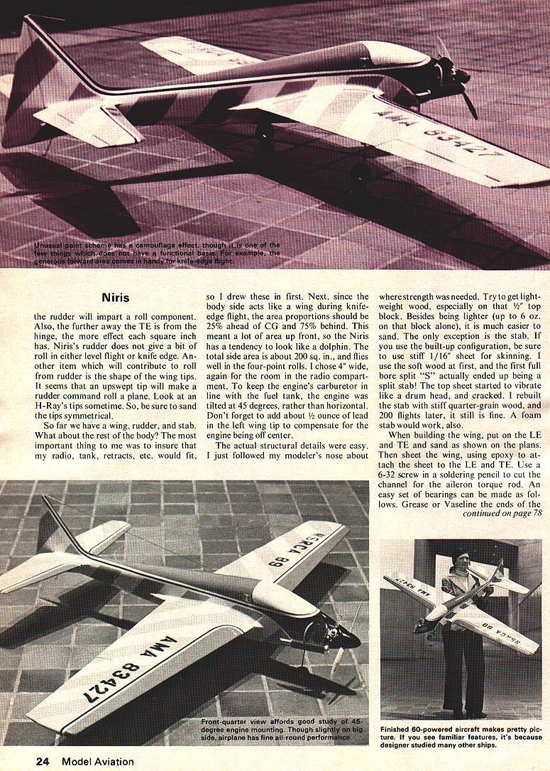
So far we have a wing, rudder, and stab. What about the rest of the body? The most important thing to me was to insure that my radio, tank, retracts, etc. would fit, so I drew these in first. Next, since the body side acts like a wing during knife-edge flight, the area proportions should be 25% ahead of CG and 75% behind. This meant a lot of area up front, so the Niris has a tendency to look like a dolphin. The total side area is about 200 sq. in., and flies well in the four-point rolls. I chose 4" wide, again for the room in the radio compartment. To keep the engine's carburetor in line with the fuel tank, the engine was tilted at 45 degrees, rather than horizontal. Don't forget to add about 1/2 ounce of lead in the left wing tip to compensate for the engine being off center.
The actual structural details were easy. I just followed my modeler's nose about where strength was needed. Try to get lightweight wood, especially on that 1/2" top block. Besides, being lighter (up to 6 oz. on that block alone), it is much easier to sand. The only exception is the stab. If you use the built-up configuration, be sure to use stiff 1/16" sheet for skinning. I use the soft wood at first, and the first full bore split 'S' actually ended up being a split stab! The top sheet started to vibrate like a drum head, and cracked. I rebuilt the stab with stiff quarter-grain wood, and, 200 flights later, it is still fine. A foam stab would work also.
When building the wing, put on the LE and TE and sand as shown on the plans. Then sheet the wing, using epoxy to attach the sheet to the LE and TE. Use a 6-32 screw in a soldering pencil to cut the channel for the aileron torque rod. An easy set of bearings can be made as follows. Grease or Vaseline the ends of the
Niris (continued)
measure and pin the ribs in place. Once the ribs and the LE are in place, it can be removed and the sheeting can be applied. Notice that the top of the rudder is narrower than the bottom. This insures a smooth line from the high point of the airfoil to the TE. Speaking of taper, don't be afraid to use sandpaper on that movable rudder you just cut from 1/32" sheet. Again, if you choose light wood, it sands easy.
A short word about control surface hinging. By all means try to get as little gap as possible. It adds drag and reduces effectiveness of the surface if there is an air gap. The best way I know is to make the front of the surface "V" shaped, and its corresponding fixed surface flat, as shown on the plans. The hinge pin should be centered at the apex of the "V", which requires that it be inset a bit on both sides of the hinge. A couple of cuts with an X-Acto knife and the job is done.
Bolt on the wing, set it level, and glue on the stab and rudder, with filler block, checking alignment as you go. A poor fit means a bad bird, so take your time. The engine cowling is easy, too. Bolt on the engine, slip F-1 over the crankshaft, put on your prop and spinner, then tape F-1 to the back of the prop with scrap 1/32" ply as a spacer. Fill in with scrap sheet and blocks, using 5-minute epoxy. Don't be afraid to put too much wood here, because after it's dry, you can plane to the engine, and go at it with your razor plane and sanding blocks. After you fuelproof the engine and tank compartments, you should be ready to apply your favorite finish.
I tried Silk-Spun Coverite on the plane, followed by two coats of acrylic lacquer primer, then wet-sanded with #400 wet/dry paper. Fill dings with auto body putty, and dust on another coat of primer. Spray the whole plane white, then mask off for color. Three coats of clear acrylic, then sand with #600 paper, wet-sand to a nice gloss.
Oh yes, about those fillets. Either Epoxilite or Micro Balloons and epoxy will work fine. Put them on after the Coverite but before the primer. Sand smooth, then paint.
A nice touch is to personalize your plane with dry-transfer lettering. These should be put on after the color, but before the clear. Just clean the area, rub on, then spray clear over them. Dust on a couple of light clear coats before laying the paint on heavy, however, or the letters may just "float" in the paint and get out of line.
If everything checks out for CG, no warps, etc., bolt in your engine, radio gear, and have fun. Flying — with the CG in the proper range, Niris is very difficult to spin. Those landings can be slowed down to practically nothing without fear of tip stall too. (I've tried.) In fact, I think you'll find Niris a real pussycat on the sticks. It goes where you point it, and is very capable of doing anything you can do. The only limitation is that it will not do a real slow snap maneuver. When the CG is moved a little rearward of that shown on the plans, don't try this unless you know what you're doing, because it can be both exciting to watch, and fun for those kids who like to pick up pieces of a broken airplane. It is more maneuverable, but also more "skittish" that way. At the proper CG, though, it has absolutely no bad characteristics, and I have passed my box to a flyer who never flew anything but gliders before. Although he had to slow it to half throttle and thought the ailerons made it very touchy, he was able to fly it without any problems. He also just loved the feel of doing an axial roll!
Transcribed from original scans by AI. Minor OCR errors may remain.

