
NIT WIT
ACTIVE FF/GAS enthusiasts who reside east of the Mississippi River are certainly aware of the seemingly endless struggle in recent years to obtain and retain suitable flying sites for competitions. Large sites have become all but extinct, and many of those currently available are much closer to the "small field" variety.
Some years ago the AMA Contest Board recognized the need to tailor Free Flight competitions according to the size of the flying field. Categories I, II, and III resulted, each with special engine-run and flight-time limits. A separate National Record tally was kept for each of the three categories.
Whether intended or not, this action instilled renewed vigor throughout the Free Flight community. The opportunity to win a contest and set a national record at the same time, even in a small-field situation, provided additional incentive and enthusiasm. The three-category system gave small-site contestants a chance to make the record books again—a feat that had become increasingly difficult at the smaller sites east of the Big Muddy. Small-field competitors were able to convert an assumed handicap into a definite challenge, and Category III contests eventually assumed a character all their own.
A case in point is the succession of contests at Wright-Patterson AFB in Dayton, OH following the 1976 AMA Nats. This affair opened previously unavailable old Wright Field to area clubs for weekend competitions. On days of little wind drift the site could sustain Category II activity. However, since the high fences that enclose the historic air base are virtually unscaleable, the four area FF clubs that sponsored meets there chose the 2-min Category III limits. We had a long series of contests providing a steady diet of 5-sec engine-run and 2-min max limits—on a superb flying site. With four different area clubs sponsoring contests on the same field on a near-monthly basis, it was a simple task to track contestant progress in attacking the 5-sec/2-min challenge.
After a couple of flying seasons the Wright-Patterson contestants began to get a good grip on the 5-sec/2-min limits. Marathon flyoffs running into double digits were not unusual. Model design and engine combinations trended toward a different solution: simply adding more power (for example, Schnuerle-ported engines) was not always the answer. Total model weight became an important factor in trying to squeeze 2 minutes of glide time out of a 5-sec engine run, and many of the powerful engines were also heavy.
By spring 1979, lightweight models built around lightweight engines began to show considerable promise. Two early success stories were Gib Robbins' superlight, rear-finned 320 sq. in. Satellite powered by a Cox TD .09, and Gil Morris' early Toothpicks series using lightweight Fox engines. Gib's model, the first consistent lightweight combination to begin edging previously dominant FAI Power entries out of Class trophy lines, culminated in winning Class B at the 1979 Lincoln Nats. The Category III contest effort helped curb the marathon flyoff situation.
In 1980 the rules were changed to trim Category III flyoff engine runs to 4 sec after the fifth max. The change eliminated some FAI Power models that were too heavy to glide 2 minutes on a 4-sec engine run. The 1980 Nats at Wright-Patterson proved the regulars up to the task; in fact, first-place trophies in Power events were taken back across the Mississippi. Ralph Prey has long maintained that building the proper model around the engine, regardless of its comparative power, can produce very satisfactory results. That philosophy applies to successful present-day Category III models.
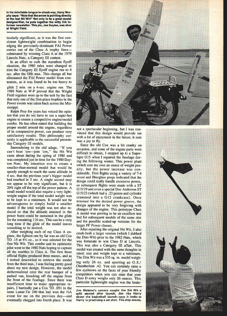
Surrendering to the old adage "can't beat 'em—join 'em," Nit Wit came about during spring 1980 and was completed just in time for the 1980 Dayton Nats. The intention was to create a smaller-than-normal model that would be speedy enough to reach the same altitude in 4 sec that the previous year's bigger model had reached in 5 sec. One second may not appear significant, but it is 20% of the power pattern. A small model also required a very lightweight engine if total model weight was to be kept to a minimum. It would not be advantageous to simply build a smaller model without reducing total weight, because the altitude attained in the power burst must be sustained in the glide for the remaining 116 sec.
After weighing each of my Class A engines, the lightest was an old Cox TD .15 at 4.25 oz., so it was selected for the first Nit Wit. This combination and its optimistic pilot went to the 1980 Nats hoping to capture all the marbles in Class A. The first three official flights produced three maxes. On the third max the model de-thermalized onto the rear bumper of a parked van, knocking the engine off the front of the fuselage. With insufficient time for proper repairs I hurriedly put a Cox TD .051 in the same Lunar-Tic 240 that had won the 1/2A event for me the previous day—and eventually finished fourth. It was not a spectacular beginning, but the design proved a joy to fly and promising.
Since the old Cox was a bit cranky and some parts were difficult to obtain, I stepped up to a Super-Tigre G15 when I repaired the fuselage that winter. This cost over an ounce of weight, but the power increase was considerable. First flights using a variety of 7-4 wood and fiberglass props indicated the design could handle excessive power, so subsequent flights were made with a ST G15/19 and even a special Doc Anderson ST G15/23 (a .23 piston and cylinder fitted into a G15 crankcase). Once trimmed for the desired power groove, the design was forgiving with engine changes. The prototype Class A model became an excellent test bed for subsequent models of the same size and for possible scaled-up versions for larger FF Power classes.
I also crash-built a larger version, the Dim-Wit, before the 1982 Nats, and it won Class D at Lincoln (a Category III affair). The Dim-Wit was created with the same thoughts in mind: size and weight kept to a minimum. It was a 535 sq. in. model weighing only 26 oz., powered by an O.S. Chamberlain .42. You can raise a few eyebrows when you state your Class D entry weighs only 26 ounces. That lightweight engine was the brainchild of a fellow CIA Club member, Meredith Chamberlain, who first took advantage of the difference in bore between later O.S. Max .40 and earlier Max-H models. Mixing parts produced a reputable engine with an interesting displacement of .42 cu. in.
This article centers on a Class A design, but the super-light engine/model theory appears to work well for other classes of Category III competition also. Incorporation of the awesome power of a Schnuerle engine isn't absolutely necessary. Think small—and think lightweight engines as well as airframes!
Engine weights (approximate)
- Class A
- O.S. Max .15 — 4.15 oz (118 g)
- Cox TD .15 — 4.25 oz (120 g)
- O.S. Max .20 — 5.5 oz (156 g)
- Ross .15 — 5.5 oz (156 g)
- Fox .19 — 5.6 oz (158 g)
- ST G15 — 5.6 oz (158 g)
- ST G15/19 — 5.6 oz (158 g)
- Class B
- O.S. Max .25 — 5.5 oz (156 g)
- ST G20/23 — 5.8 oz (165 g)
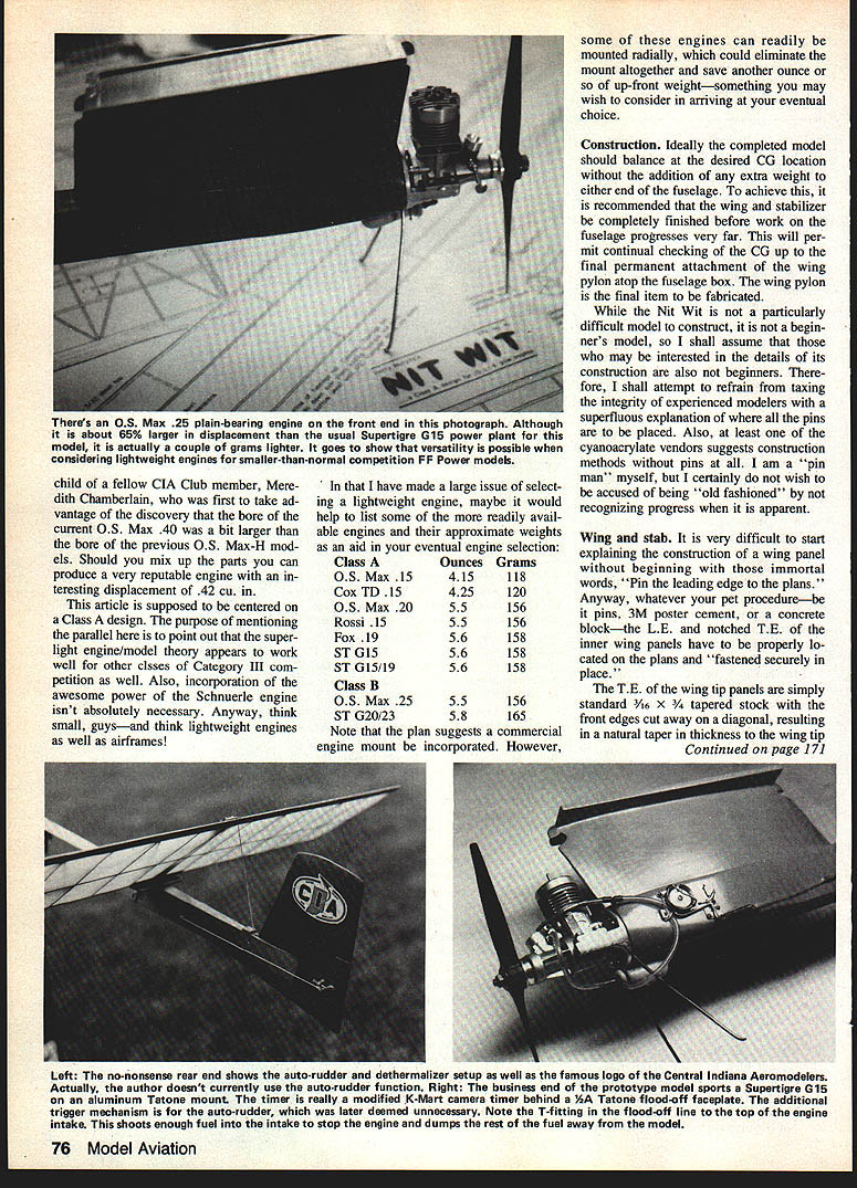
Note: The plan suggests incorporating a commercial engine mount. However, some of these engines can be mounted radially, which could eliminate the mount altogether and save another ounce or so of up-front weight.
Construction
Ideally the completed model should balance at the desired center of gravity (CG) location without adding extra weight to either end of the fuselage. To achieve this, finish the wing and stabilizer before progressing far on the fuselage. This permits continual checking of the CG up to the final permanent attachment of the wing pylon atop the fuselage box. The wing pylon is the final item to be fabricated.
While the Nit Wit is not a particularly difficult model to construct, it is not a beginner's model. I will therefore avoid over-explaining basic procedures. Follow your preferred construction methods (pins, 3M poster cement, etc.)—I am a "pin man" myself but recognize the value of newer techniques such as pinless cyanoacrylate methods.
Wing and stab
- Pin the leading edge and notched trailing edge of the inner wing panels to the plans and secure them flat to the workbench to prevent warpage as the panels leave the plans.
- The wing tip panels use standard 3/16 x 3/4 tapered stock with the front edges cut on a diagonal to produce a natural thickness taper toward the tip.
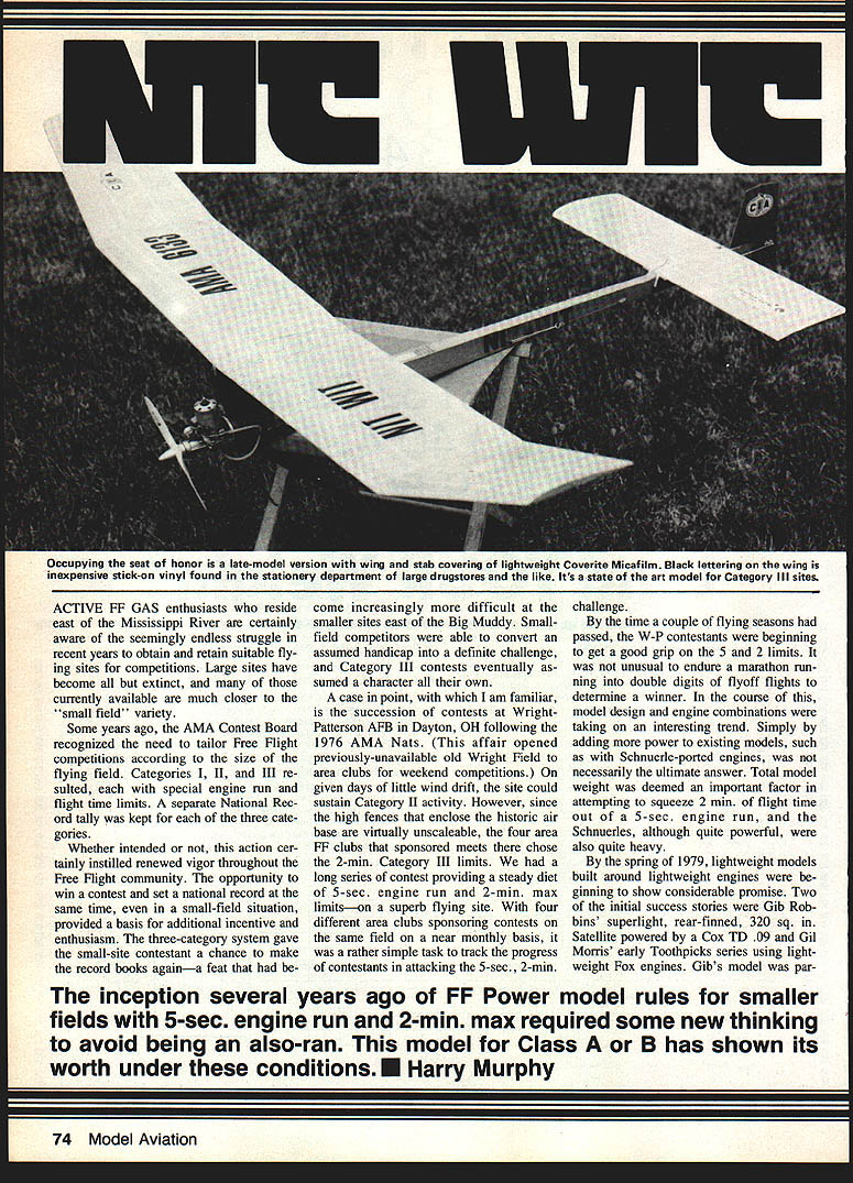
- The late-model version has the wing and stab covered with lightweight Coverite Micafilm. The black lettering on the wing is inexpensive stick-on vinyl found in the stationery department of large drugstores.
- Each panel should be secured flat while drying. Internal diagonal bracing should not be omitted; the airfoil is thin and requires bracing for anti-warp.
- Permanently assemble the four individual wing panels as with any other wing. Be sure mating ends are properly beveled and aligned in plan view, incorporating the respective 4-in polyhedral and 1-in dihedral. Add 3/32-in ply joint braces and proper gussets as indicated on the plans.
- Stab construction is much the same; the plans are self-explanatory.
- Sand and prepare both the wing and stab for covering with a material of good tensile strength. The original was covered with silkspan and dope, giving great strength to a thin airfoil, but silkspan absorbed fuel and gradually increased weight. I now prefer Coverite’s lightweight white Micafilm for fuel-proofing and skin stress properties.
Fuselage
The Nit Wit uses a narrow, tapering balsa box fuselage with engine-mount cheeks for a pleasing silhouette. Use 3/32-in balsa sheet from C-grain stock for the fuselage top—this becomes the backbone to which the pylon is attached.
- Build the fuselage upside down over the plans. Cement the rectangular 1/8-in plywood former centers in place at the locations shown.
- Assemble the 1/16-in sheet sides next. Add 1/2-in triangular balsa blocks to all four inside corners of the forward compartment before attaching the 1/16-in sheet bottom.
- The 1/4-in sheet balsa cheeks can be added after removing the box from the plans; pre-bevel them for ease in carving.
- Use a disc sander or similar tool to face off the front of the fuselage before adding the 3/32-in plywood firewall laminates. Epoxy these in place after drilling mounting holes and installing blind nuts to retain the engine mount. Attach the mount and carve/sand the front end to the desired shape.
- Carve the cover for the stab piano-wire skid into the front of the firewall with an appropriate router or a Dremel Moto-Tool.
- The vertical fin is cemented together over the plans from four pieces of 1/8-in sheet balsa; use selected hard stock (or basswood) for the lower skid portion. After attaching the fin to the fuselage, add the 1/8-in sheet doubler and 1/8-in ply stab mount. The assembly is then ready for final finishing.
Temporarily assemble the engine, mount, skid, fuel titer, and completed stab to approximately locate the all-important CG. Mark this longitudinal point on the inside of the fuselage box. Sand the fuselage on its side over the plans to check the fore-and-aft relationship to the balance point as marked on the pylon detail. If the balance point is slightly aft of the front edge of the yet-to-be-fabricated pylon, wood may protrude forward of the firewall; adjust the leading edge of the pylon accordingly.
Build the trapezoidal pylon keel over the plans with proper alignment and any needed leading-edge adjustments. Cement the left-side contour parts (PA and PB) and the slanting vertical 3/32 x 1/16-in strips and other 3/32-in strips as the keel is secured over the plans. Add the right-side parts after removing the assembly from the plans. After finishing and sanding the pylon framework to symmetry, plank it with 1/16-in balsa sheet with the grain running parallel to the slanted uprights. Trim and finish-sand, then cement the 3/32-in sheet wing platform securely to the top of the pylon.
Determine the exact CG location with all parts assembled in their correct position, then permanently cement the pylon to the top of the fuselage box. Use epoxy or a cyanoacrylate such as Super "T" for the attachment; cellulose cements may not be reliable.
Cover fuselages with colored tissue or silkspan using nitrate dope. After a few coats of dope, fog on a thin coat of clear K&B Super Poxy. I usually add a heavier color coating of Super Poxy around the engine and pylon areas to ward off fuel problems and add contrasting color.
Accessories are largely a matter of personal preference. An auto-rudder was used on the prototype but was omitted on the subsequent model as unnecessary—the model has plenty of speed at end-of-run to coast into a flat right-right glide pattern without an automatic "fin-kicker."
Final assembly, trim and preflight
- Thoroughly check the finished Nit Wit for warps and proper alignment. The stab must be perfectly flat and free of warps.
- Wing tips should be washed-out about 1/16 in and no more than 3/32 in.
- The left inner panel should be flat; the right inner panel should have about 1/16 to 3/32 in of wash-in.
- Check settings repeatedly over a few days with a steamy teakettle to guarantee permanent settings.
- The rudder should be warped no more than about 1/2 in to the right to compensate for right wing wash-in.
- Mount the engine with about 1/2° of left side thrust.
- Run the engine a number of times to ensure an initial timer setting of about 3 sec. The model will get away quickly after launch.
I am an advocate of the vertical launch theory: if the model is trimmed with no drastic warps and launched vertically or nearly so, it will travel directly away from the ground. If slightly out of trim, it will take more time than 3 sec to turn around and come back at you. Since the ultimate launch angle will be about 80° to the ground anyway, why waste time with low-angle trimming when you can point the model straight up, run the engine for a 3-sec test hop, and get the scary stuff over with quickly?
The Nit Wit design has been a most enjoyable one for me. I hope you find it as enjoyable. See you downwind!
—Harry Murphy
Transcribed from original scans by AI. Minor OCR errors may remain.

