
NJ One Design
Club project makes scratch-building as much fun as flying
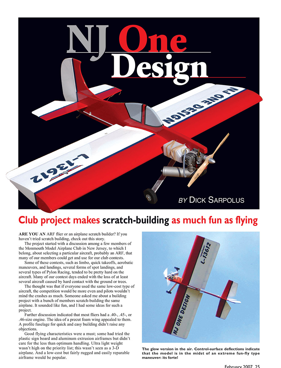
By DICK SARPOLUS
Are you an ARF flier or an airplane scratch builder? If you haven't tried scratch building, check out this story.
The project started with a discussion among a few members of the Monmouth Model Airplane Club in New Jersey, to which I belong, about selecting a particular aircraft, probably an ARF, that many of our members could get and use for our club contests.
Some of these contests, such as limbo, quick takeoffs, aerobatic maneuvers and landings, several forms of spot landings, and several types of pylon racing, tended to be pretty hard on the aircraft. Many of our contest days ended with the loss of at least several aircraft caused by hard contact with the ground or trees.
The thought was that if everyone used the same low-cost type of aircraft, the competition would be more even and pilots wouldn't mind the crashes as much. Someone asked me about a building project with a bunch of members scratch-building the same airplane. It sounded like fun, and I had some ideas for such a project.
Further discussion indicated that most fliers had a .40-, .45-, or .46-size engine. The idea of a precut foam wing appealed to them. A profile fuselage for quick and easy building didn't raise any objections.
Good flying characteristics were a must; some had tried the plastic sign-board and aluminum-extrusion airframes but didn't care for the less-than-optimum handling. Ultra-light weight wasn't high on the priority list; this wasn't seen as a 3-D airplane. And a low-cost but fairly rugged and easily reparable airframe would be popular.
Design
I laid out the wing first, with a thick, full symmetrical airfoil. It had a 48-inch span and a 14-inch chord for 672 square inches of wing area. The slab-profile fuselage length was made 40 inches—compact overall, with good proportions for lively flying. I used large built-up control surfaces, but not aimed at 3-D flying. Weight was calculated to be approximately 4 pounds, for a wing loading of 14 ounces per square foot. That's light, and if the model came in slightly heavier it would still be good.
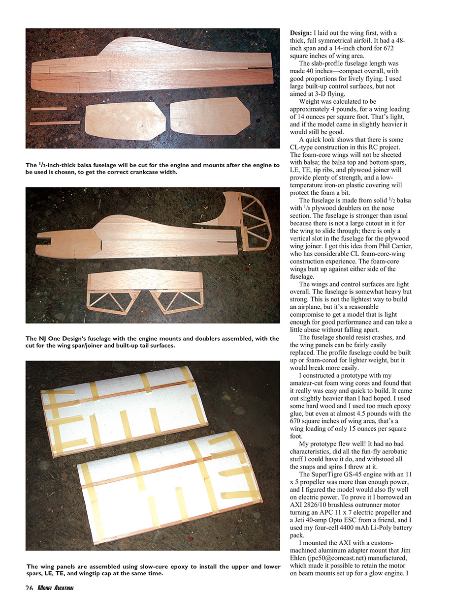
A quick look shows that there is some CL-type construction in this RC project. The foam-core wings will not be sheeted with balsa; the balsa top and bottom spars, LE, TE, tip ribs, and plywood joiner will provide plenty of strength, and a low-temperature iron-on plastic covering will protect the foam a bit. The fuselage is made from solid 1/2" balsa with 1/8" plywood doublers on the nose section. The fuselage is stronger than usual because there is not a large cutout in it for the wing to slide through; there is only a vertical slot in the fuselage for the plywood wing joiner. I got this idea from Phil Cartier, who has considerable CL foam-core-wing construction experience.
The foam-core wings butt up against either side of the fuselage. The wings and control surfaces are light overall. The fuselage is somewhat heavy but strong. This is not the lightest way to build an airplane, but it's a reasonable compromise to get a model that is light enough for good performance and can take a little abuse without falling apart. The fuselage should resist crashes, and the wing panels can be fairly easily replaced. The profile fuselage could be built up or foam-cored for lighter weight, but it would break more easily.
I constructed a prototype with my amateur-cut foam wing cores and found that it really was easy and quick to build. It came out slightly heavier than I had hoped. I used some hard wood and I used too much epoxy glue, but even at almost 4.5 pounds with the 672 square inches of wing area, that's a wing loading of only 15 ounces per square foot. My prototype flew well! It had no bad characteristics, did all the fun-fly aerobatic stuff I could have it do, and withstood all the snaps and spins I threw at it. The SuperTigre GS-45 engine with an 11 x 5 propeller was more than enough power, and I figured the model would also fly well on electric power. To prove it I borrowed an AXI 2826/10 brushless outrunner motor turning an APC 11 x 7 electric propeller and a Jeti 40-amp Opto ESC from a friend, and I used my four-cell 4400 mAh Li-Poly battery pack.
I mounted the AXI with a custom-machined aluminum adapter mount that Jim Ehlen (jpe50@comcast.net) manufactured, which made it possible to retain the motor on beam mounts set up for a glow engine. I put the battery pack in place of the fuel tank. I left the throttle servo and radio battery in place; using a BEC would have made the electric power installation even lighter.
The airplane balanced roughly the same as with the glow engine and flew well—almost the same as with the SuperTigre. I tried different propellers; with an APC 12 x 8 electric the AXI drew somewhat more than 600 watts. I think the 2826/12 would have been a better motor choice for this application.
I figured that if I built this airplane specifically for electric power, the plywood nose doublers could be thinner, the maple engine mounts would be eliminated, and a firewall mount would be used, making that version a good amount lighter than the glow-powered version.
So I built a second model for electric power. The results were great, and the glow vs. electric comparison is discussed in more detail in an accompanying sidebar.
Now that I knew the design worked, I arranged to have Phil Cartier at The Core House (34 Sweet Arrow Dr., Hummelstown PA 17036) cut the foam wing cores using his computer-controlled setup, which does a great job. The cores are now commercially available from The Core House.
I worked up a wood materials list, and with mail-order prices (I like Lone Star Balsa) it would cost less than $20 for the wood. I made the landing gear from 1/8" x 1" 6061-T6 aluminum, but usable commercial aluminum and composite gears are available from several manufacturers.
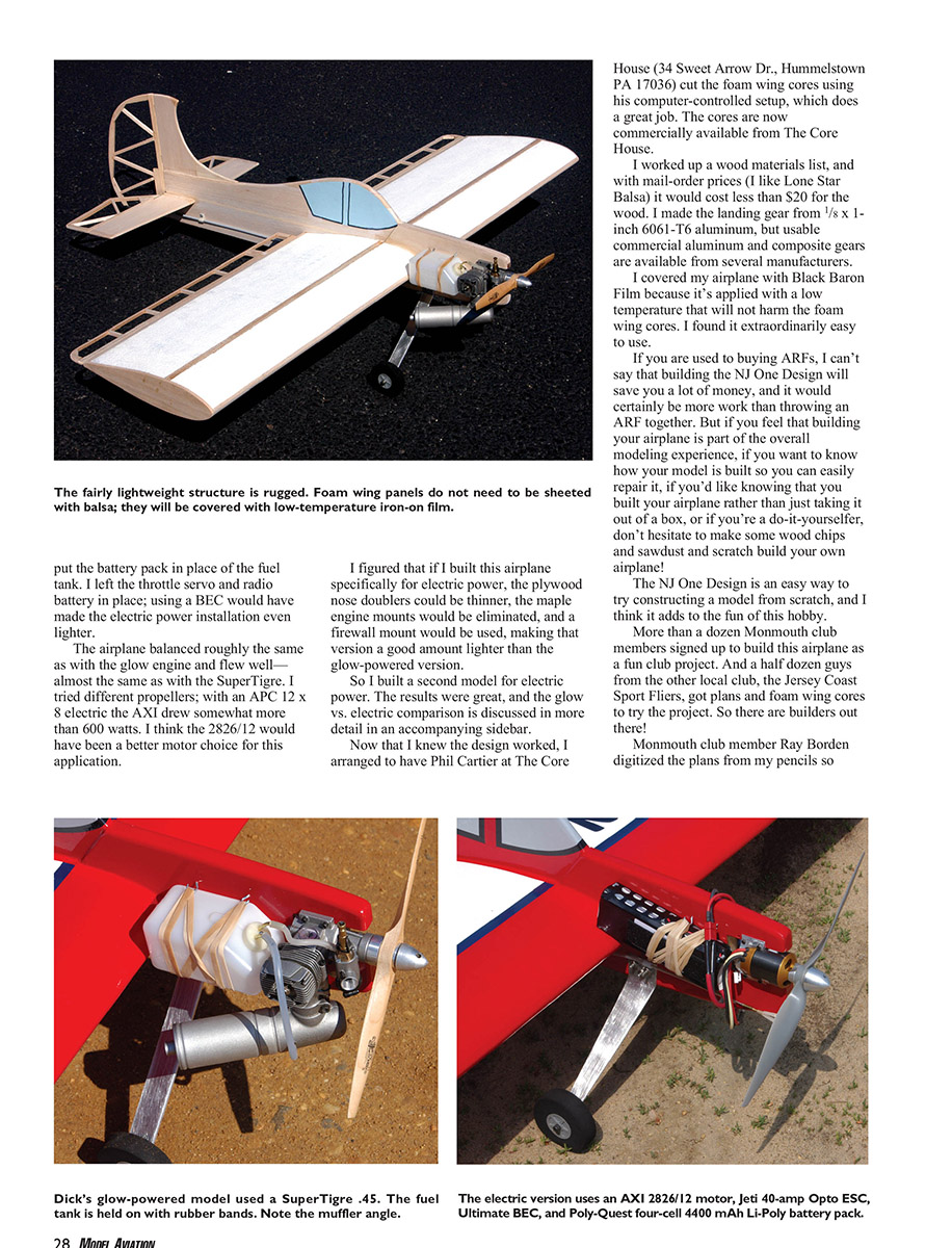
I covered my airplane with Black Baron Film because it's applied with a low temperature that will not harm the foam wing cores. I found it extraordinarily easy to use.
If you are used to buying ARFs, I can't say that building the NJ One Design will save you a lot of money, and it would certainly be more work than throwing an ARF together. But if you feel that building your airplane is part of the overall modeling experience, if you want to know how your model is built so you can easily repair it, if you'd like knowing that you built your airplane rather than just taking it out of a box, or if you're a do-it-yourselfer, don't hesitate to make some wood chips and sawdust and scratch build your own airplane!
The NJ One Design is an easy way to try constructing a model from scratch, and I think it adds to the fun of this hobby.
More than a dozen Monmouth club members signed up to build this airplane as a fun club project. And a half dozen guys from the other local club, the Jersey Coast Sport Fliers, got plans and foam wing cores to try the project. So there are builders out there!
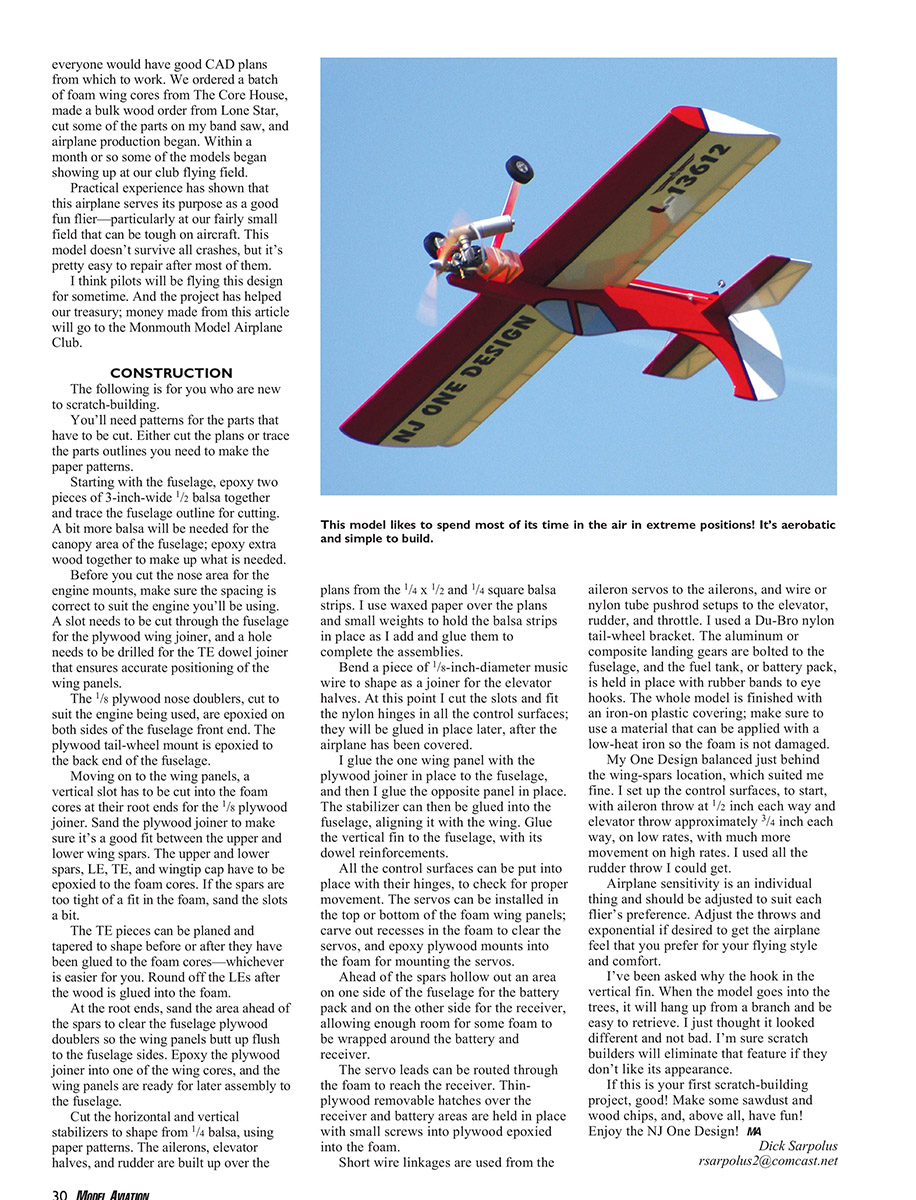
Monmouth club member Ray Borden digitized the plans from my pencils so everyone would have good CAD plans from which to work. We ordered a batch of foam wing cores from The Core House, made a bulk wood order from Lone Star, cut some of the parts on my band saw, and airplane production began. Within a month or so some of the models began showing up at our club flying field.
Practical experience has shown that this airplane serves its purpose as a good fun flier—particularly at our fairly small field that can be tough on aircraft. This model doesn't survive all crashes, but it's pretty easy to repair after most of them.
I think pilots will be flying this design for some time. And the project has helped our treasury; money made from this article will go to the Monmouth Model Airplane Club.
NJ One Design Wood List
Fuselage
- 1/2 x 3 x 36 balsa — Two pieces (fuselage)
- 3/8 x 1/2 maple — One piece (engine mounts)
- 1/8 x 6 x 12 plywood — Two pieces (nose doublers)
Wings
- 3/8 x 1/2 x 36 balsa — Four pieces (spars)
- 1/4 x 1/2 x 36 balsa — Two pieces (LE)
- 3/8 x 1/2 x 36 balsa — Two pieces (TE)
- 1/8 x 6 x 12 plywood — One piece (wing joiner)
- 1/8 x 3 x 36 balsa — One piece (wingtips)
- 1/4 x 1/2 x 36 balsa — Two pieces (ailerons)
- 1/4 x 1/4 x 36 balsa — Three pieces (ailerons)
Tail Surfaces
- 1/4 x 3/4 x 36 balsa — One piece (stabilizer, fin)
- 1/4 x 1/2 x 36 balsa — Two pieces (elevator, rudder)
- 1/4 x 1/4 x 36 balsa — Two pieces (elevator, rudder)
Built-Up Wing, Ribs, and Sheeting
(or foam wing core by The Core House)
- 1/8 x 3 x 36 balsa — Five pieces (ribs)
- 3/32 x 4 x 36 balsa — Two pieces (sheeting)
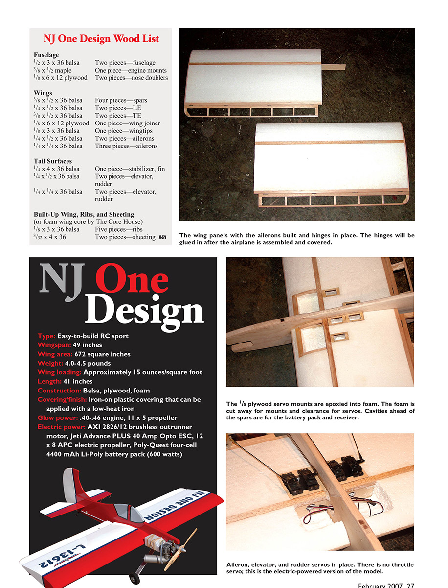
Specifications
- Type: Easy-to-build RC sport
- Wingspan: 49 inches
- Wing area: 672 square inches
- Weight: 4.0–4.5 pounds
- Wing loading: Approximately 15 ounces/square foot
- Length: 41 inches
- Construction: Balsa, plywood, foam
- Covering/finish: Iron-on plastic covering that can be applied with a low-heat iron
- Glow power: .40–.46 engine, 11 x 5 propeller
- Electric power: AXI 2826/12 brushless outrunner motor, Jeti Advance PLUS 40 Amp Opto ESC, 12 x 8 APC electric propeller, Poly-Quest four-cell 4400 mAh Li-Poly battery pack (600 watts)
(Note: the design text earlier references a 48-inch wing span and a 40-inch fuselage length; the specifications above reflect the dimensions presented in the published spec block.)
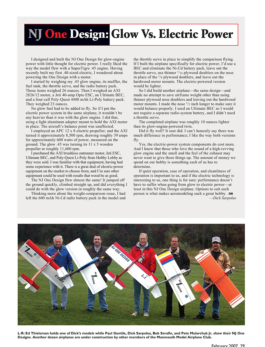
NJ One Design: Glow vs. Electric Power
I designed and built the NJ One Design for glow-engine power with little thought for electric power. I really liked the way the model flew with a SuperTigre .45 engine. Having recently built my first .40-sized electric, I wondered about powering the One Design with a motor.
I started by weighing my .45 glow engine, its muffler, the fuel tank, the throttle servo, and the radio battery pack. Those items weighed 26 ounces. Then I weighed an AXI 2826/12 motor, a Jeti 40-amp Opto ESC, an Ultimate BEC, and a four-cell Poly-Quest 4400 mAh Li-Poly battery pack. They weighed 23 ounces.
No glow fuel had to be added to fly. So if I put the electric power system in the same airplane, it wouldn't be any heavier than it was with the glow engine. I did that, using a light aluminum adapter mount to hold the AXI motor in place. The aircraft's balance point was unaffected.
I employed an APC 12 x 8 electric propeller, and the AXI turned it approximately 8,500 rpm, drawing roughly 39 amps for approximately 600 watts of power, measured on the ground. The glow .45 was turning its 11 x 5 wooden propeller at roughly 11,600 rpm.
I purchased the AXI brushless outrunner motor, Jeti ESC, Ultimate BEC, and Poly-Quest Li-Poly from Hobby Lobby as they were sold. I was familiar with that equipment, having had some experience with it. There is a great deal of electric-power equipment on the market to choose from, and I'm sure other equipment could be used with results that would be as good.
The NJ One Design flew almost the same! It jumped off the ground quickly, climbed straight up, and did everything I could do with the glow version in roughly the same way.
Thinking more about the weight-comparison issue, I had left the 600 mAh Ni-Cd radio battery pack in the model and the throttle servo in place to simplify the comparison flying. If I built the airplane specifically for electric power, I'd use a BEC and eliminate the Ni-Cd battery pack, leave out the throttle servo, use thinner 1/16" plywood doublers on the nose in place of the 1/8" plywood doublers, and leave out the hardwood motor mounts. The electric-powered version would be lighter.
So I did build another airplane—the same design—and made no attempt to save airframe weight other than using thinner plywood nose doublers and leaving out the hardwood motor mounts. I made the nose 1/2" longer to make sure it would balance properly. I used an Ultimate BEC so I would not require a separate radio-system battery, and I didn't need a throttle servo.
The completed airplane was roughly 10 ounces lighter than its glow-engine-powered twin.
Did it fly well? It sure did. I can't honestly say there was much difference in performance; I like the way both versions fly.
Yes, the electric-power system components do cost more. And I know that those who love the sound of a high-revving glow engine and the smell and the feel of the exhaust may never want to give those things up. The amount of money we spend on our hobby is something each of us has to determine.
If quiet operation, ease of operation, and cleanliness of operation is important to us, and if the electric technology is interesting to us, one thing is for sure: performance doesn't have to suffer when going from glow to electric power—at least in this NJ One Design airplane. Options to suit each person is what makes aeromodeling such a great hobby.
—Dick Sarpolus
Construction
The following is for those who are new to scratch-building.
You'll need patterns for the parts that have to be cut. Either cut the plans or trace the parts outlines you need to make the paper patterns.
Starting with the fuselage, epoxy two pieces of 3-inch-wide 1/2" balsa together and trace the fuselage outline for cutting. A bit more balsa will be needed for the canopy area of the fuselage; epoxy extra wood together to make up what is needed.
Before you cut the nose area for the engine mounts, make sure the spacing is correct to suit the engine you'll be using. A slot needs to be cut through the fuselage for the plywood wing joiner, and a hole needs to be drilled for the TE dowel joiner that ensures accurate positioning of the wing panels.
The 1/8" plywood nose doublers, cut to suit the engine being used, are epoxied on both sides of the fuselage front end. The plywood tail-wheel mount is epoxied to the back end of the fuselage.
Moving on to the wing panels, a vertical slot has to be cut into the foam cores at their root ends for the 1/8" plywood joiner. Sand the plywood joiner to make sure it's a good fit between the upper and lower wing spars. The upper and lower spars, LE, TE, and wingtip cap have to be epoxied to the foam cores. If the spars are too tight of a fit in the foam, sand the slots a bit.
The TE pieces can be planed and tapered to shape before or after they have been glued to the foam cores—whichever is easier for you. Round off the LEs after the wood is glued into the foam.
At the root ends, sand the area ahead of the spars to clear the fuselage plywood doublers so the wing panels butt up flush to the fuselage sides. Epoxy the plywood joiner into one of the wing cores, and the wing panels are ready for later assembly to the fuselage.
Cut the horizontal and vertical stabilizers to shape from 1/4" balsa, using paper patterns. The ailerons, elevator halves, and rudder are built up over the plans from the 1/4 x 1/2 and 1/4 square balsa strips. I use waxed paper over the plans and small weights to hold the balsa strips in place as I add and glue them to complete the assemblies.
Bend a piece of 1/8"-diameter music wire to shape as a joiner for the elevator halves. At this point I cut the slots and fit the nylon hinges in all the control surfaces; they will be glued in place later, after the airplane has been covered.
I glue the one wing panel with the plywood joiner in place to the fuselage, and then I glue the opposite panel in place. The stabilizer can then be glued into the fuselage, aligning it with the wing. Glue the vertical fin to the fuselage, with its dowel reinforcements.
All the control surfaces can be put into place with their hinges, to check for proper movement. The servos can be installed in the top or bottom of the foam wing panels; carve out recesses in the foam to clear the servos, and epoxy plywood mounts into the foam for mounting the servos.
Ahead of the spars hollow out an area on one side of the fuselage for the battery pack and on the other side for the receiver, allowing enough room for some foam to be wrapped around the battery and receiver.
The servo leads can be routed through the fuselage to the receiver. Thin plywood removable hatches over the receiver and battery areas are held in place with small screws into plywood epoxied into the fuselage.
Short wire linkages are used from the aileron servos to the ailerons, and wire or nylon-tube pushrod setups to the elevator, rudder, and throttle. I used a Du-Bro nylon tail-wheel bracket. The aluminum or composite landing gears are bolted to the fuselage, and the fuel tank, or battery pack, is held in place with rubber bands to eye hooks. The whole model is finished with an iron-on plastic covering; make sure to use a material that can be applied with a low-heat iron so the foam is not damaged.
My One Design balanced just behind the wing-spars location, which suited me fine. I set up the control surfaces, to start, with aileron throw at 1/2" each way and elevator throw approximately 3/4" each way, on low rates, with much more movement on high rates. I used all the rudder I could get.
Airplane sensitivity is an individual thing and should be adjusted to suit each flier's preference. Adjust the throws and exponential if desired to get the airplane feeling that you prefer for your flying style and comfort.
I've been asked why the hook in the vertical fin. When the model goes into the trees, it will hang from a branch and be easy to retrieve. I just thought it looked different and not bad. I'm sure scratch builders will eliminate that feature if they don't like its appearance.
If this is your first scratch-building project, good! Make some sawdust and wood chips, and, above all, have fun! Enjoy the NJ One Design!
Dick Sarpolus rsarpolus2@comcast.net
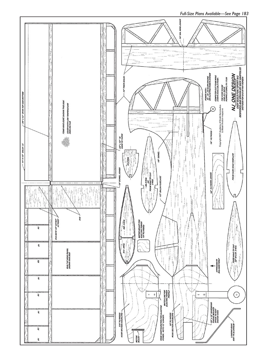
No article text appears on this scanned page. The page contains full‑size plans/graphics and part labels for the NJ One Design (drawings only).
Transcribed from original scans by AI. Minor OCR errors may remain.

