
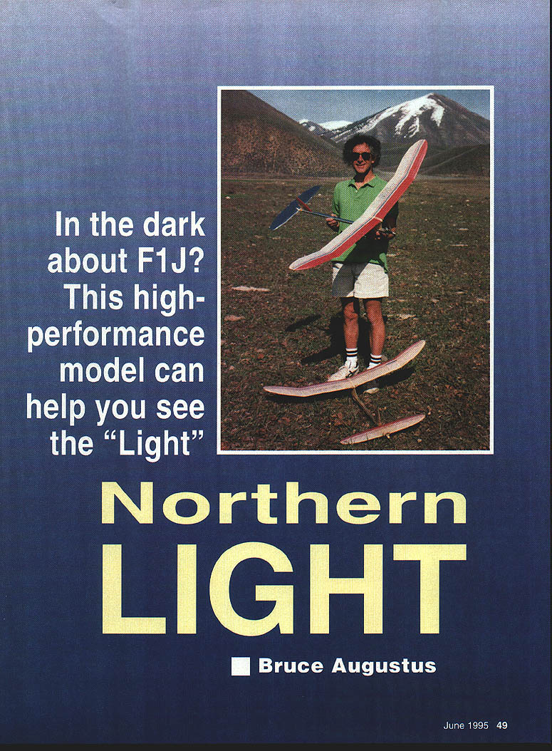
Northern LIGHT
In the dark about F1J? This high-performance model can help you see the "Light"
F1J is perhaps the fastest-growing free-flight event. Originally comprised mainly of 1/2A fliers, it has now attracted participants from most power classes, including F1C (the large FAI power class). The event is flown at most major AMA and FAI contests, and beginning in 1995 it has been included in the prestigious Americas Cup competition. It has even been suggested that F1J should replace F1C for the Junior World Champs.
Two schools of thought have evolved concerning the best way to design an F1J model. One group believes that since F1C airplanes are the epitome of power models, a good F1J should emulate F1C. This has produced a family of mini-F1C designs best represented by Bill Lynch's Pegasus and Dave Parsons' Cathexis Redux. These airplanes are high-aspect-ratio, full-bunting, synthetic-material, technological wonders and they fly very well.
The other school of thought, represented by Northern Light, is that the rules of F1J are substantially different from those of F1C and the designs should take advantage of the F1J rules. The F1J rules are more like AMA gas than FAI, so the design process began with an AMA-type airplane. Exotic materials are not needed for strength nor to meet a minimum weight. In spite of the availability of space-age materials, models built from balsa still produce the lightest 1/2A airplanes.
Northern Light has been under development since October 1989. The design objective was to build a simple fixed-tail F1J that would fly as well as an auto-surface airplane. The goal was to avoid dependence on complex mechanical devices such as heavy multifunction timers, and therefore have an airplane that was reliable and easy to fly. The requirements demanded inherent stability, low drag, and light weight.
Maybe it's old-fashioned, but careful design and fixed geometry can still achieve ultra-high performance. Ultimate performance may require ultimate-technology equipment, but one of the chief attractions of F1J over F1C is that ultimate performance is not yet necessary. With only five rounds to fly, contests usually finish in one day and the long flyoff rounds are in the afternoon instead of a 10-minute dawn flyoff as in F1C. The event still frequently boils down to thermal picking.
The current (third) version of Northern Light differs from the prototype only in minor ways: covering material and stab size were changed, the pylon has been lowered and narrowed, and a timer-start button has been added. Airframe drag is minimized by a tapered-tube fuselage, built-up pylon and fin, recessed timer, internal fuel bladder, and internal DT and rudder lines. The built-up pylon and fin have lower drag than flat structures and are less critical to construction misalignment.
Key design data
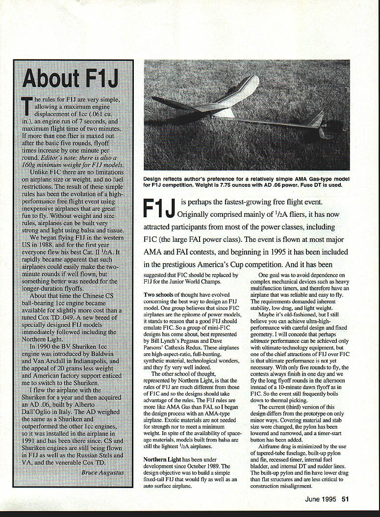
- Weight: flying weight about 220 grams (7.75 oz), propeller excluded.
- Propeller: APC 5.7 x 3.
- Engine: AD .06 expected to turn about 26,000–27,000 rpm on high-nitro fuel.
- Wing loading: 3.4 ounces per square foot.
- Aspect ratio: 8.8.
- Wing section: 8.5% thick.
- Stabilizer area: 26% of the wing, section 8.4% thick.
- Center of gravity (CG): at 78% (of chord).
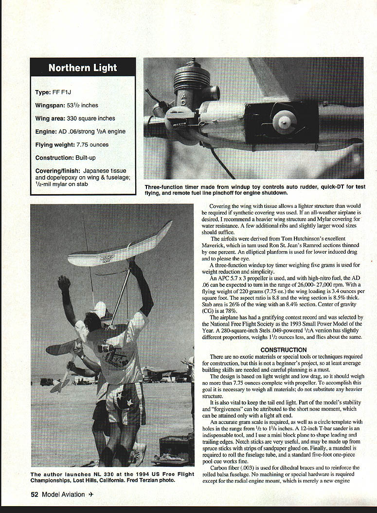
- Timer: three-function windup toy timer weighing about 5 grams.
- Variants: a 280 sq. in. Stels .049-powered 1/2A version has slightly different proportions, weighs about 1.5 oz less, and flies similarly.
Northern Light enjoyed a gratifying contest record and was selected by the National Free Flight Society as the 1993 Small Power Model of the Year.
CONSTRUCTION
No exotic materials, special tools, or techniques are required. This is a reasonable beginner's project for someone with at least average building skills. Careful planning must be given to light weight and low drag; the finished model should weigh no more than 7.75 ounces complete (propeller excluded). To accomplish this goal it is necessary to weigh materials — substituting heavier structure will defeat the purpose. It is also vital to keep the tail end light: part of the model's stability and forgiveness can be attributed to a short nose moment, which is attained by a light aft end.
Tools and materials
- Accurate gram scale.
- Circle templates (hole sizes from 1/2 to 1-1/8 inches).
- 12-inch T-bar sander (indispensable).
- Mini block plane for shaping leading and trailing edges.
- Notch sticks (spruce sticks or strips wrapped with sandpaper).
- Mandrel to roll the fuselage tube.
- Tissue covering for a lighter structure (Mylar recommended for all-weather versions; increase structure strength if using synthetic covering).
Airfoils were derived from Tom Hutchinson's Maverick, which in turn used Ron St. Jean's Ramrod sections thinned by one percent. An elliptical planform is used for lower induced drag and aesthetics.
A three-function windup toy timer (about 5 g) is used for weight reduction and simplicity.
Wing
I usually build the wing first so it can be doped while building and the fuselage is rigged. Tissue covering yields a high stiffness-to-weight ratio; synthetic coverings are not recommended unless the structure is beefed up.
Select all lumber for the wing before beginning. All balsa weights refer to a 3 x 36 sheet or a 36-inch stick (not wood density).
Typical weights and stocks
- 1/8" square main spar caps: 2–2.5 grams each.
- Leading and trailing edges: 4–5 g stock.
- Ribs: 13 g stock (dihedral break ribs 18–20 g).
- Aft spar: ~1.2 g sufficient.
- Spruce sticks for forward spars: about 2 g.
- 1/32" spar web: 10–11 g wood.
Construction notes
- Place heavier wood on the right wing if lumber weights aren't perfect; add a small tip ballast if necessary.
- Cut parallel ribs (including half-ribs) and notch for spars with a spruce notch stick; make notches tight.
- Cut diagonal ribs slightly oversize and do not notch for the aft spar initially. Drill a 1/16" vent hole in each rib.
- Build center panels first; create 3/32" wash-in in the right main panel only.
- Glue parallel ribs, half-ribs, and gussets. Use a balsa diehold template to set angles on center and polyhedral ribs.
- Install top spar cap, forward spars, and 1/32" vertical-grain shear web.
- Notch diagonal ribs after installation using a long notch stick guided by previously cut parallel rib notches. Glue aft spar, then sand rib tops roughly to shape with the T-bar.
- Remove center panels from plan and shape the leading edge with a mini block plane. Final-sand the top of the wing so ribs are alike.
- Build tip panels similarly, but cant the trailing edge of the polyhedral rib 1/8" outboard to create slight sweepback (acts like washout). Reduce thickness of two outboard ribs so the top spar bends gradually to tip.
- Block up panels for dihedral and wash-in, fit rib angles in the jig, glue panels together with slow CyA, sand, then press carbon-fiber dihedral braces (.003" carbon fiber) in place with waxed paper. Sand excess glue. Before applying carbon fiber, sand the surface well to remove any mold-release.
Stabilizer
- Cut all ribs the same size from 10–12 g (7/16" balsa) and notch for all three spars. The stabilizer airfoil is 8.4% — final-sand between 1/32" and 1/16" to reach this thickness before covering.
- Pin tip pieces on the plan and glue leading and trailing edge laminations with white or nitrocellulose glue (Ambroid) to save weight.
- Fit bottom spar cap and doublers; shape trailing edge with a plane or sanding block. Set bottom notch of each rib on the bottom spar cap and trim rib ends to fit.
- Deepen top notches of the three outboard ribs slightly so top spars bend down to the tip; shape ribs with a T-bar.
- Typical weights: spars 1–1.2 g; leading edge laminates 1.3 g; trailing edge laminates 1.5 g.
- Drill a vent hole in each rib and avoid excess glue.
Fuselage
The fuselage is a rolled tube formed on a standard pool cue using A-grain balsa about 12–14 g. Cut a 36"-long trapezoid (1-1/2" one end, 1/2" the other). This may be obtained by cutting two trapezoids from a 3" sheet and gluing them together.
- Soak and dope the wood to start the curl, wrap around the pool cue and wind with an Ace bandage to dry overnight. Wrap the cue with waxed paper and ensure it is well varnished.
- Remove the tube from the mandrel, sand edges, remount, and glue. Push formers down the tube from the forward end using a long 1/2" dowel and drip-glue in place.
- Use circle templates slid onto the fuselage to determine former sizes. Formers can be inserted, tried, and released by turning them edgewise.
- Install 1/16" nylon tubing guides for the DT and auto rudder lines before former seven is installed. Formers seven and eight have solid centers to seal and epoxy the fuel bladder compartment.
- If using a timer-start button, install a 1/16" nylon guide tube through the bladder compartment along the fuselage inner wall, keeping bends gentle to avoid binding the .020" trip wire.
- After former eight is installed, roll a sheet of 1/32" balsa to fit as an internal doubler and glue with slow CyA; do not glue the seam until the doubler is in place.
- The exact locations of formers are not critical as long as there is room for the bladder and timer.
Engine and mount
- The engine is mounted on a screw-in backplate; blind nuts for engine mounting are installed in the firewall before it is glued in place. Offset the engine 20° to the right so the exhaust clears the pylon opposite the timer. A light exhaust extension can be made from an aluminum cigar tube, high-temperature epoxy, and aircraft safety wire.
- Mount the firewall as square as possible; resolve any misalignment in favor of slight down and left thrust.
Reinforcements and timer compartment
- Cut eight strips of .003" carbon fiber 1/8" wide, sand and glue to the tube with medium or slow CyA.
- Cut the timer hole with a fine-tooth razor saw so the faceplate fits flush with the fuselage skin.
- Glue blocks to formers at the front and rear of the timer compartment to support the timer and accept mounting screws. Harden screw holes with thin CyA.
- Glass from firewall back to the edge of the timer compartment with 0.75 oz cloth using medium CyA.
Pylon and fin
- Build the pylon from very light 1/32" balsa (no more than 7.5 g per sheet). Cut the center core to exact shape and glue perpendicular to the bottom pylon rib (1/16" stock, ~15 g sheet).
- Add two rectangular side formers and the top rib. Leave side pieces slightly oversize at top and bottom for fairing into the fuselage and wing mount.
- Be careful when gluing the first side piece — this determines pylon straightness. Trim excess and glue the other side.
- Use the wing to form the correct wing mount angle; apply full-length strips of .003" carbon fiber to stiffen pylon edges. Sand the dihedral angle into the pylon top using a T-bar sander and attach the wing mount.
- Fit the pylon to the fuselage by wrapping 150-grit sandpaper around the fuselage 12" aft of the pylon location and sanding the pylon bottom until the bottom rib is partially contoured (3/8" to 1/2" wide). Check incidence before gluing. If you are not using an engine and timer with a combined weight of about 70 g, consider gluing the pylon on last to ensure correct balance.
- Fit and attach the fin in the same manner as the pylon. Draw alignment lines on the fuselage to mount both straight.
Alternate fuselage
- The article shows an alternate fuselage version: 1 mil hard aluminum foil wrapped around the balsa tube instead of visible carbon fiber. Techniques for that fabrication are beyond this article; see Randy Archer (1991 NFFS Symposium). Both fuselage types are equivalent in strength and weight.
MECHANISMS
This airplane is designed for a rear-race engine weighing about 64 g. A screw-in backplate mount avoids the extra weight of a beam mount. The fuel bladder is 3/16" surgical tubing with about 1/32" wall thickness and roughly 3/4" long with a knot in one end; it is located aft of the timer to minimize CG shift as fuel is burned. An engine-mounted pinchoff device is used with monofilament line running to the timer.
Windup toy timers are preferred for reliability and vibration resistance. They can be assembled quickly and save about half an ounce over commercial timers. A detailed construction article for lightweight timers appears in the 1994 NFFS Symposium.
Timer functions and installation
- The timer provides remote fuel pinchoff, auto rudder, and a five-second delay DT for test flights (a fuse DT is used for official flights). The timer may be single-function so long as it can provide engine stop and simultaneous rudder-line release.
- Timer levers should be formed so engine and rudder lines do not come off when levers actuate. This eliminates re-hooking lines between flights.
- The timer-start button is located just behind the fuel bladder compartment. A length of fine music wire inside a guide tube contacts the timer pawl; releasing the button frees the pawl. Locate the DT fuse far enough aft of the start switch so the airplane may be launched without burning fingers.
Auto rudder
- The auto rudder provides consistent transitions from the power phase to glide. It is a safety device and a convenient fine-trim adjustment.
- The rudder is held during power by the monofilament rudder line and released at engine stop, then pulled over by an unthreaded elastic band.
- Two timer levers are used: one releases forward for the engine-mounted fuel pinchoff and the other releases aft for the rudder. They are arranged to release simultaneously, although the rudder lever can be adjusted for timing if necessary.
- Normal rudder limits: center to about 3/32" right.
COVERING AND FINISH
- Cover fuselage, pylon, and fin with tissue and finish with butyrate dope. Apply a coat of K&B Super Poxy or equivalent to the entire fuselage to prevent fuel damage. Apply additional coats from the firewall back to former four.
- Coat the inside of the timer compartment and slosh several coats of epoxy in the bladder compartment to protect against bladder failure. Allow each coat to dry overnight and avoid exposure to fuel for a week.
- The stabilizer is covered with 1/2 mil aluminized Mylar, with clear MonoKote wrap at the center to prevent abrasion during DT motion. 1/4 mil Mylar can be used for less weight but is fragile and must be dyed or painted for visibility.
- Cover wing center rib bays with tissue and dope two coats. Then cover the entire wing so center bays are double covered, preserving wash-in.
- The center bays should receive a coat of Super Poxy (or the whole wing depending on expected nitro use). Do not overdo epoxy — it is heavy.
PREFLIGHT
- Check that Northern Light balances as shown on the plans and add ballast if necessary. For first flights the CG may be up to 1/8" forward, but not aft. If using engines less powerful than an AD .06, leave the CG 1/8" forward.
- Ensure there are no thrust offsets; shim as required. Make sure the wing is keyed to the fuselage and the auto rudder has an appropriate rubber band.
- Set rudder straight for power phase and about 1/16" right for glide. Test glide with rudder straight and no stab tilt; the airplane should glide in a wide right circle due to wing wash-in.
- Stretch a rubber band from the DT line to the quick DT lever on the timer.
FLYING
Northern Light is easy to fly and requires only the DT fuse and band to be installed between flights. The launch is not critical — do not throw the model; simply release it.
- Set engine timer for 3–4 seconds (no less) and launch the airplane straight up with the engine near full power on mild fuel. Do not attempt low-power test flights.
- The model should accelerate very fast in a nearly vertical climb or right spiral with a left roll. (Northern Light rolls left as it turns right; the wash-in causes the right wing to rise against the right turn, keeping the nose up in the climb.)
- If the model appears to lay over to the right just before the engine cuts, this is normal — it is the effect of the auto rudder, and the perceived timing is due to sound delay.
- If trimming is required, adjust the rudder in very small increments (no more than .010"). Keep engine time about four seconds until the pattern is correct.
- Northern Light can be flown straight up with no turn, or with a slight right turn. The right turn is recommended because trimming straight up is less forgiving.
- If the airplane turns too tightly to the right even with rudder straight, add a little left thrust shim or reduce incidence by shimming up the leading edge of the stab by .010" increments. Tail ballast may be required to compensate glide.
- If the nose does not point skyward in climb, consider adding additional wash-in (3/32" should usually suffice).
- Once the four-second power pattern is correct, switch to high-nitro fuel, run at maximum rpm, and repeat. Increase engine time in one-second increments once satisfied.
- After engine cutoff the airplane should coast upward for a second or two and then begin a right glide without stalling or diving. The right power turn and auto rudder combine to achieve the right glide circle.
- If the model drops into a dive after cutoff, usually the nose is too high when speed falls due to insufficient auto rudder. If rudder adjustment cannot cure it, increase decalage and move the CG forward. Once power and transition are trimmed, do not change decalage.
- Cut a DT fuse for about one minute and observe the glide: a large slow circle of about 40 seconds to 1 minute is expected. Change glide airspeed with ballast; change circle diameter with rudder. Do not reduce rudder offset below what is needed for safe transition; if large diameter changes are required, use stab tilt.
- Slow the glide with tail weight until a slight stall is observed, then remove a small amount of weight. On windy days reduce circle time to about 35 seconds by increasing glide rudder deflection.
Northern Light is versatile: it has flown in AMA 1/2A Categories I and II in addition to F1J. Once trimmed for the seven-second F1J engine run, the time can be increased for AMA flying with little change required.
Expect day-to-day differences and begin each flying session with a four- to five-second test flight. The airplane goes very fast and invisible changes (dope curing, fuel residue) may require slight adjustments. The adjustments are minor but necessary for consistent performance.
SOURCES
- AD Engines: Bill Lynch, 11137 Creekhaven Court, Auburn, CA 94602.
- Timer start device, gadgets, and covering materials: Starline International, 6146 E. Cactus Wren Road, Scottsdale, AZ 85253.
- Carbon fiber and glass cloth: Bradley Model Products, 1337 Pine Sap Court, Orlando, FL 32825.
- Carbon fiber and aluminum fuselage tubes: Ken Oliver, 2213 El Cejo Circle, Rancho Cordova, CA 95670.
- Carbon fiber fuselage tubes: Ron McBurnett, 2265 Greenwood Road, Rickreall, OR 97371.
- Tissue and other supplies: Champion Model Products, 880 Carmen Court, La Verne, CA 91750.
- Fuel and other supplies: Aerodyne, 1924 E. Edinger, Santa Ana, CA 92705.
- 1/2 mil aluminized Mylar: Bruce Augustus, Box 450, Sun Valley, ID 83353.
- Mylar covering material: MRL, 25108 Marguerite #160, Mission Viejo, CA 92692.
- Symposium reports: NFFS Publications (Fred Terzian), 4858 Moorpark Ave., San Jose, CA 95129.
Transcribed from original scans by AI. Minor OCR errors may remain.

