
Northrop XB-35
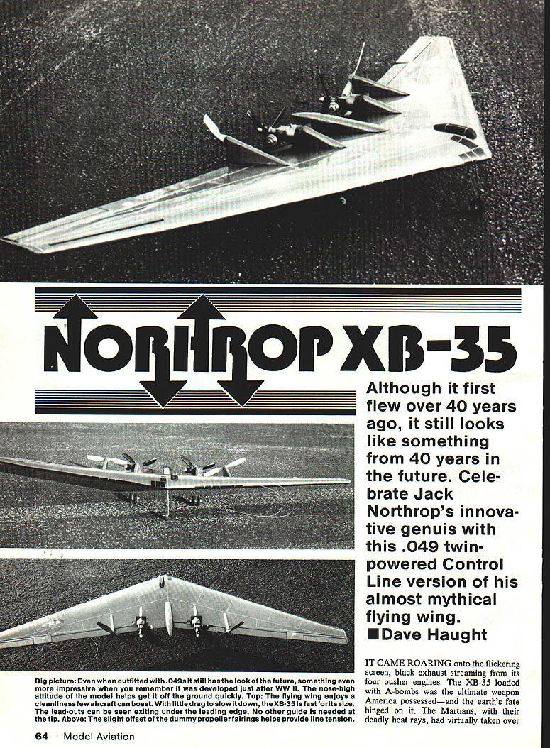
Although it first flew over 40 years ago, it still looks like something from 40 years in the future. Celebrate Jack Northrop's innovative genius with this .049 twin-powered Control Line version of his almost mythical flying wing. Dave Haught
It came roaring onto the flickering screen, black exhaust streaming from its four pusher engines. The XB-35, loaded with A-bombs, was the ultimate weapon America possessed—and the earth's fate hinged on it. The Martians, with their deadly heat rays, had virtually taken over.
A world now, the intrepid bomber—mankind's last hope—was being sent to decimate the merciless invaders. Distinctly strange-looking, the bomber had no tail, no fuselage, just a huge wing to deliver nuclear nightmare. In the midst of the advancing forces the bomb found its mark, the enemy kept coming. Mankind doomed. Well, it didn't turn out that way, at least in the movie.
I remember sitting mesmerized throughout the classic 1945 silverscreen version of H. G. Wells' War of the Worlds. One thing that stuck in my mind most was the sight of the Northrop XB-35 tearing off to save the world. The audience's glimpse of that strange, wonderful craft—would we ever get to see such a machine? The arrow often travels a circular path; the wonderfully futuristic shape of the XB-35 is making a comeback in the guise of something called the Stealth plane.
Media attention given to a plastic Stealth model recently released by Testors sparked old memories and made me once again think about building a Control Line version of this phenomenal airplane. "Stealth" has become a generic word for futuristic fighters and bombers currently being built and flown in secret places around the world. Interestingly enough, current articles on stealth designs often single out Northrop flying wings of the late 1930s and '40s. Although not necessarily designed as stealth concepts, these very futuristic flying wings—lacking vertical surfaces and with their steep sweepback—make natural radar avoidance. In fact, one could take the XB-35 design, upgrade the power plants and add radar-absorbing materials and paints to have a very efficient, effective Stealth bomber.
Rumor has it that a secret Northrop Stealth bomber design program is currently underway, adopting an approach along those lines. We'll wait and see. In the meantime, you too can build your own Stealth bomber.
Northrop XB-35/Haught Continued from page 66
The highly sweptback wing of the XB-35 had a slight oscillation back and forth that necessitated installing what was then a highly advanced automatic control system built by Honeywell. Usually, models of a full-scale aircraft that was in the tricky-to-fly category will prove correspondingly difficult to maneuver. This thought kept the XB-35 sitting on my "build it someday" list. But when the media began running all those neat pictures and articles on Stealth, I got the bug again. I blew up a set of rather poor three-view drawings I had, and hung them on the shop wall to look at.
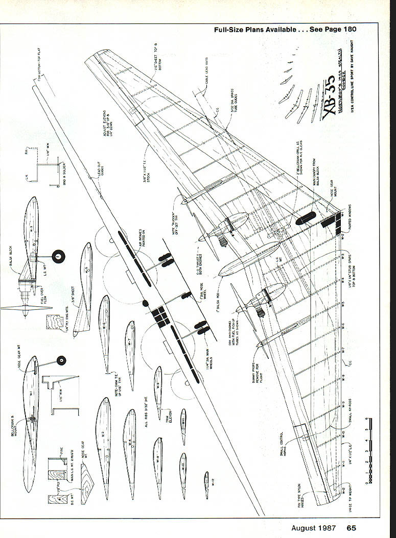
First I imagined it as a four-motor electric model, but the reality of rigging four shaft extensions, etc., became overwhelming. I just wanted to build a flying model, not an engineering marvel. On the other hand, four gas engines, even using .049s, would make for a huge model, and with the CG location it would take a ton of lead to balance properly. Laying two .049s down on the drawings sold me on a twin. The 48-in. wingspan would make for a good amount of area, and the thick section would supply plenty of lift for the needed nose weight. Since the three-views I was working from weren't the best I would have to settle for a semiscale model. That was all right, since by this time I just wanted to see it in the air.
As the design and construction progressed, an avalanche of problems and questions began to present themselves, challenging my meager aerodynamic training. Where should I balance? Where to locate the bellcrank? How about the line rake, the sweep? What kind of thrust line for the engines to keep it out on the lines? I could have pondered the questions forever, but I knew I had to bite the bullet. With each new question, I convinced myself of at least one good answer. I kept coming back to the old control-line axiom: If it has enough power and is super-nose-heavy, it has to go around in a circle as long as it has lines on it.
As it turned out, the model flew right off the first time I took it out—and it's a flight I'll never forget. It tracked solidly on the lines for half of the circle, rotated, and flew. It is super-smooth and has a flight groove not unlike a .35-powered Stunter. The control response was excellent—and single-engine performance was just as good, only a bit slower. The glide is another story. Let's say it's best to have it down on the deck before the last engine stops. The angle of flight without power is not quite 45°.
Control-line construction, unfortunately, makes assembly time-consuming. The XB-35 has lots of ribs, formers, doublers, and sheeting. The wing uses double spars and is sheeted top and bottom so the result is a pretty beefy wing. The basic structure is easy to build if you follow the plans. I used thin balsa gussets on the top and bottom of the ribs to hold everything in alignment as the sheeting was applied. The wing panels are pinned to the board and aligned with a long straightedge while gluing.
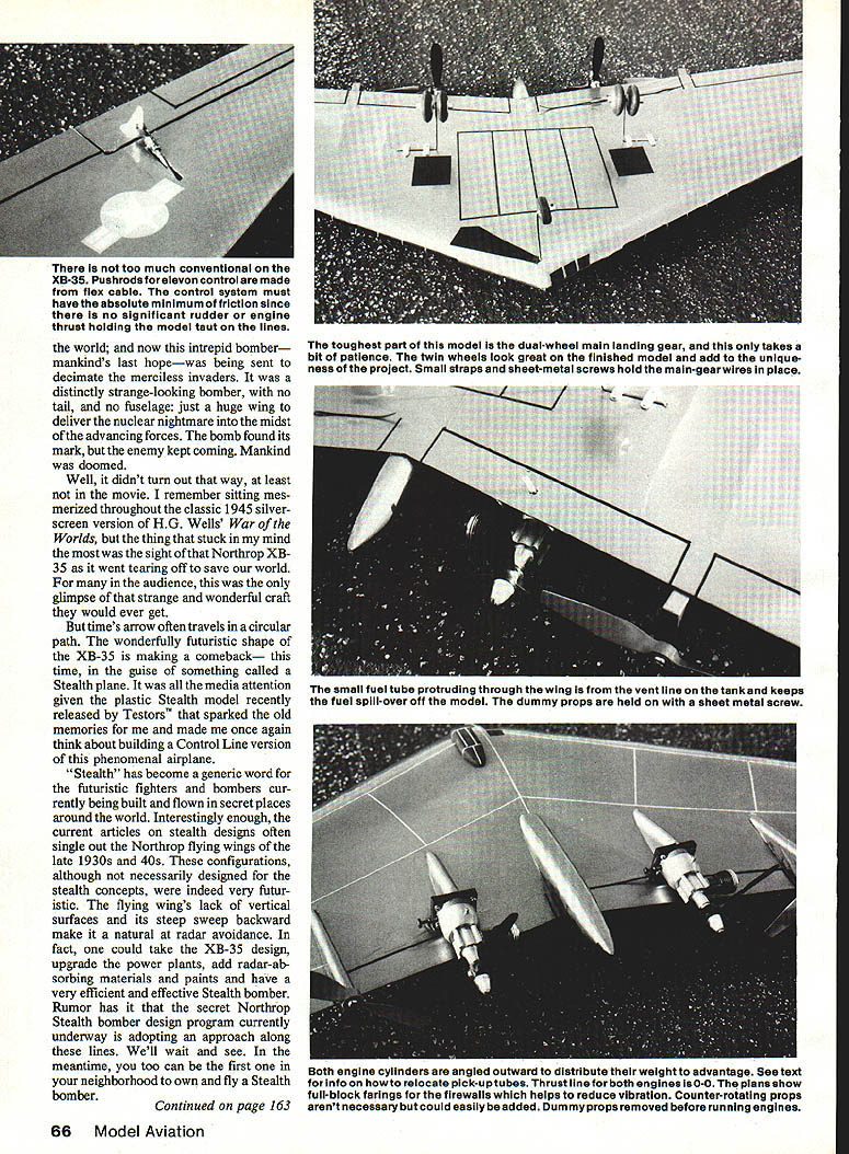
Too much conventional pushrod control made me opt for a flex-cable control system. It must have absolute minimum friction since there is no significant rudder or engine thrust holding the model taut on the lines — the toughest part of this model.
The dual-wheel main landing gear takes a bit of patience to install. Twin wheels look great when finished and add uniqueness to the project. Small straps and sheet-metal screws hold the main-gear wires in place. A small fuel tube protruding through the wing vent keeps fuel spillover off the model. Dummy props are held with a sheet-metal screw. Both engine cylinders are angled outward to distribute weight.
See the plans for pickup-tube relocation details. The thrust line for both engines is as shown on the plans. Full-block fairings and a proper firewall help reduce vibration. Counter-rotating props aren't necessary but could easily be added. Dummy props must be removed before running the engines.
The sight of it in the air made all the deliberations and head-scratching worthwhile. It definitely has the strange, eerie look of something out of space and time, and its flight performance matches its science-fiction shape. Enough of the salad; let's build one.
Construction
Overview
- Cut out all the plywood parts first, drilling any holes required. Study the plans before beginning construction. Notice that the wing section is semi-symmetric.
- The wing is built in two halves and will later be joined to incorporate the dihedral.
- The easiest and most accurate way to build the wing is:
- Cut the ribs on a flat-bottomed template.
- Assemble the wing on a straight, flat building board.
- Shim up the trailing edge stock 1/16 in., and glue everything together.
- After both wing halves are completed, remove them from the building board, glue the bottom halves of the ribs on, and sand to shape.
Detailed procedure
- Cut out all ribs and label them.
- Pin down the trailing edge (along with the shims to hold it in position) and the leading edge.
- Glue the ribs in place with cyanoacrylate (CYA).
- Once a wing panel is built, cut out the elevons and then cut them back as seen in W-9 to allow for full down movement.
- Hinge the elevons with pin-type RC hinges. It is very important that all control surfaces operate with an absolute minimum of friction.
- Notch the upper surfaces of W-1 through W-4 for the top stub spar.
- Pin the wing panels and the spar down to the bench upside-down. This will make the top of the wing flat, and the bottom will have the 1 in. of dihedral required.
- While the wing is upside-down, cut and install the bottom of the ribs and the lower stub spar.
- Install the nose gear mount and bellcrank mount, as well as the main landing gear blocks.
- Measure equal distance from either side of the center of the bellcrank and drill two holes to accept the RC-type clevises shown on the plans. Do not use a metal bellcrank with the RC clevises.
- Sew the lead-out tubes to the bottom of the leading edge and give them a good soaking with CYA glue.
- Bolt the bellcranks in place and drill the lead-outs and Ny-Rod holes. Use the smallest control rods you can get to help hold down friction in the linkage.
- Add the elevon horns and hook up the pushrods. My model has 3/8 in. up and 3/4 in. down control movements. Adjust your own to somewhere in this range.
- Glue a small tip weight to the outboard wing tip and sand the wing for the planking.
- Use medium-light 1/16 sheeting to plank the top leading edge, and the top and bottom center-section. Leave the bottom leading edge uncovered at this time.
- Notch the trailing edge for the firewalls. Make sure they are perpendicular to the centerline.
- Set up the engines for 0° offset both horizontally and vertically. Fit the firewalls and carve the fairing blocks to fit nicely, then glue them into position.
Landing gear and wheels
- Sew the nose gear securely to the mount and epoxy the whole works.
- Bend the wire for the main gear struts to shape. The XB-35 has a distinctive dual-wheel gear that looks superb, but it takes effort to pull off in the model.
- If you are not into wire bending you may want to switch to single wheels. If the dual wheels appeal to you, bend the loop end of the wire first, then work your way up the strut making each bend as you come to it.
- Bind and solder an axle at right angles to the strut and parallel to the upper part, as shown in the drawing. Add the main gear wheels at this time.
- Williams Brothers' smooth contour wheels look good on the main gear, and the nose gear gets finished off with a wheel manufactured by Perfect.
Final assembly and finishing
- Mount the engines and props and begin adding lead to the nose until the model balances. It will take quite a bit, and you will have to beef up the ribs around the weight (using wood supports) so that the lead does not fly through the model on a hard landing.
- Final balancing will be done after the model is completely finished, by adding lead solder to the nose gear.
- Once satisfied with the balance point, remove the engines, plank the bottom leading edge, and add the cap strips on the W-5 ribs.
- Finish-sand the wing and cover it with your favorite method. Mustang Silver MonoKote was used on the author’s model.
- After covering, add the dummy prop fairings. Put them on at a bit of an angle, as shown on the plans, so they will act as a rudder offset for line tension. Just a small amount of offset helps a lot and is not noticeable.
- Carve the canopy and fuselage pod from balsa blocks and fit in place.
- Paint and trim. The original XB-35 was finished in natural aluminum with stars-and-bars insignia on the upper left and lower right wing panels. Add panel lines and flap outlines with trim tape as desired. The dummy propellers overlay the real props and must be removed before running the engines.
Before bolting the engines on for the last time, remove their backplates and relocate the fuel pickup tubes as shown in the plans. Test run and tune the engines before heading out to the flying field. Always fly twin-engined models on steel lines (40-ft. lines seem a good length for this model). Tie the model to a 1/8-in. safety cable that is fixed to the ground. Too many models have been lost when a line broke in midair. Don't be a statistic.
With the balance point as shown on the plans and no warps, the XB-35 should be ready to fly. Be prepared for a crowd to form as you set up to fly.
A word needs to be said about safety. Twins are fun, but you need a border of safety around the engines. It is easy to get your jacket or leg or thumb caught in a spinning propeller while trying to start the other. The best advice is to just be alert. As a twin pusher with props in close proximity to each other, the XB-35 demands an extra measure of vigilance.
Start the outboard engine first, and tune it to a rich run. Carefully start the second engine and then sync up both fuel tanks. Tune the engines to a synchronous pitch, and hang on. The best launching position for your ground crew is to hold the model by the outboard wing between the dummy engine and the elevon.
Let the model run to build up speed and line tension, then ease in the up elevator and you're off, into the wild blue of yesterday—or is it tomorrow? Take your choice!
Transcribed from original scans by AI. Minor OCR errors may remain.

