
Notes On Pattern Aircraft Design
When it comes to areas and proportions, many scratch builders are up a tree. This useful data will dispel the aura of mystery.
Richard C. Scamehorn
SCRATCH DESIGN criteria isn't much available. It's one thing to scratch build from plans... it's another thing to design yourself a plane, but the general criteria for full-scale aircraft design holds true for RC aircraft design.
Basic aircraft design begins with trying to answer the question, "What will be the gross weight of the plane?" (Gross meaning "all-up" weight in RC terms.) While this article will deal with RC planes, if we understand the rationale of full-scale design, we can better understand the principles of application to RC design. Anyhow, the gross weight is established for two basic reasons: (1) To ensure we can carry enough passengers and cargo (mission), and (2) To give us a basis for designing sufficient wing area.
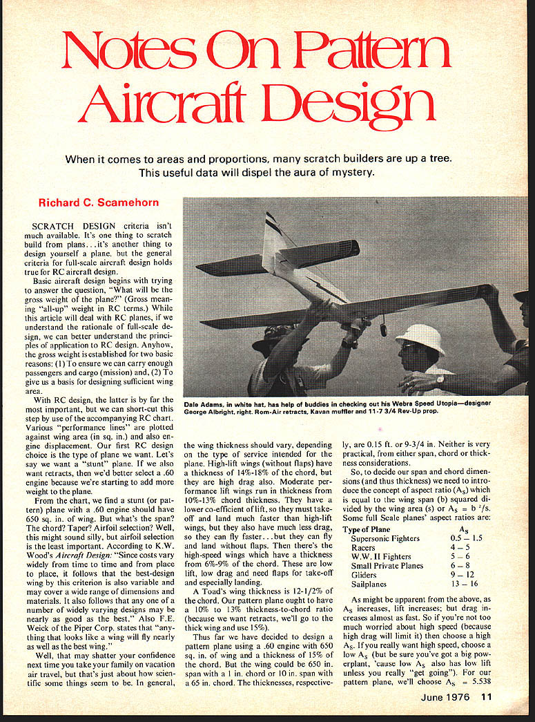
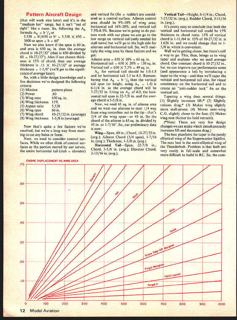
With RC design, the latter is by far the most important, but we can short-cut this step by use of the accompanying RC chart. Various "performance lines" are plotted against wing area (in sq. in.) and also engine displacement. Our first RC design choice is the type of plane we want. Let's say we want a "stunt" plane. If we also want retracts, then we'd better select a .60 engine because we're starting to add more weight to the plane.
From the chart, we find a stunt (or pattern) plane with a .60 engine should have 650 sq. in. of wing. But what's span? The chord? Taper? Airfoil selection? Well, this might sound silly, but airfoil selection is the least important.
According to K. W. Woods' Aircraft Design: "Since costs vary widely from time to time and place to place, it follows that the best-design wing by this criterion is also variable and may cover a wide range of dimensions and materials. It also follows that any one of a number of widely varying designs may be nearly as good as the best." Also F. E. Weick of Piper Corp. states that "any one thing that looks like a wing will fly nearly as well as the best wing."
Well, that may shatter your confidence next time you take your family on vacation or travel, but that's just about how scientific some things seem to be. In general, the wing thickness should vary, depending on the type of service intended for the plane. High-lift wings (without flaps) have a thickness of 14%-18% of the chord, but they are high drag also. Moderate performance lift wings run in thickness from 10%-13% chord thickness. They have a lower coefficient of lift, so they must take off and land much faster than high-lift wings, but they also have much less drag, so they can fly faster... but they can fly and land without flaps. Then there's the high-speed wings which have a thickness from 6%-9% of the chord. These are low lift, low drag and need flaps for take-off and especially landing.
A Toad's wing thickness is 12-1/2% of the chord. Our pattern plane ought to have a 10% to 13% thickness-to-chord ratio (because we want retracts, we'll go to the thick wing and use 15%).
Thus far we have decided to design a pattern plane using a .60 engine with 650 sq. in. of wing and a thickness of 15% of the chord. But the wing could be 650 in. span with a 1 in. chord or 10 in. span with a 65 in. chord. The thicknesses, respectively, are 0.15 in. or 9-3/4 in. Neither is very practical, from either span, chord or thickness considerations. So, to decide our span and chord dimensions (and thus thickness) we need to introduce the concept of aspect ratio (As) which is equal to the wing span (b) squared divided by the wing area (s) or As = b^2 / s.
Some full-scale planes' aspect ratios are:
- Type of Plane - As
- Supersonic Fighters - 0.5 – 1.5
- Racers - 4 – 5
- W.W. II Fighters - 5 – 6
- Small Private Planes - 6 – 8
- Gliders - 9 – 12
- Sailplanes - 13 – 16
As might be apparent from the above, as As increases, lift increases; but drag increases almost as fast. So if you're too worried about high speed because high drag will limit it, then choose a high As. If you really want high speed, choose a low As; be sure you've got a big powerplant, because low As also has low lift unless you really get going. For our pattern plane, we'll choose As = 5.538.
From the As formula As = b^2 / s, b^2 = As × s = 5.538 × 650 = 3600, so span = 60 in. Now also know span 60 in., area 650 sq. in., average chord = 10-27/32 in. (650 divided by 60). Also chosen thickness 15% chord, average thickness = 15% × 10-27/32 ≈ 1-5/8 in. We'll get significance of average later.
So, a little design knowledge and a few decisions, we've designed the following criteria: 1 Mission 2 Power 3 Wing area 4 Wing thickness 5 Aspect ratio 6 Wing span 7 Wing chord 8 Wing thickness
Pattern plane: .60 engine, 650 sq. in., 15% thickness, As = 5.538, span = 60 in., chord = 10-27/32 in., average thickness ≈ 1-5/8 in. average
Now that's quite a few factors we've resolved—a long way from starting to cut balsa or foam. Next need to consider control surfaces. Often think control surfaces portion moved servos entire horizontal tail stab at
Pattern Aircraft Design
and vertical fin (fin + rudder) are considered as a control surface. Aileron control area should be 9%-10% of wing area; horizontal tail 16%-20%, and vertical tail 7.5%-8.5%. Because we're going to do pattern work with our plane we can go to the low range on vertical tail (only needed for stall turns) but we'll go to the high side for ailerons and horizontal tail. So, we'll multiply the wing area by these factors and we get:
- Aileron area = 650 × 10% = 65 sq. in.
- Horizontal tail = 650 × 20% = 130 sq. in.
- Vertical tail = 650 × 7.5% = 49 sq. in.
As for vertical tail should be 1.0-1.8; and for horizontal tail 3.5-4.5. Remembering that As = b^2/s then the vertical tail span (or height, using As = 1.4) is 6-1/4 in., so the average chord will be 2-27/32 in. Using an As of 4.0, the horizontal tail span is 22-7/8 in. and the average chord is 5-5/8 in.
Now, we need 65 sq. in. of aileron area and we want our ailerons to start 1/4 way from wing centerline out to the tip — that's 3/4 of the wing span — or 45 in. So, the chord of the aileron is 65 sq. in. divided by 45 in. or 1-7/16 in.
So, our preliminary data is now:
- Wing — Span, 60 in.; Chord, 10-27/32 in. (avg.); Aileron Chord (3/4 span), 1-7/16 in. (avg.); Thickness, 1-5/8 in. (avg.).
- Horizontal Tail — Span, 22-7/8 in.; Chord, 5-5/8 in. (avg.); Elevator Chord, 2-13/16 in. (avg.).
- Vertical Tail — Height, 6-1/4 in.; Chord, 2-27/32 in. (avg.); Rudder Chord, 3-15/16 in. (avg.).
It's pretty easy to conclude that both the vertical and horizontal tail could be 15% thickness-to-chord ratio. 15% of vertical chord is 11-1/64 in. 15% of 10-27/32 in. is 1-11/64 in. and we could change that to 1-5/8 in., which is convenient.
Well we're getting closer, but there's still a way to go. This then brings us to wing taper and explains why we used average chord. Our constant chord is 10-27/32 in., but we can improve our performance some (and appearance a lot) by introducing a taper to the wing — and then we'll taper the vertical and horizontal tail also, for consistency on the horizontal tail and to create an "anti-rudder lock" fin on the vertical tail.
Tapering a wing does several things:
- Slightly increases lift;
- Slightly reduces drag;
- Makes wing stall more stall-prone;
- Moves semi-wing C.G. slightly closer to the fuse;
- Makes wing root thicker (to hold retracts).
*Note: There are very few design changes we can make which simultaneously increases lift and decreases drag.
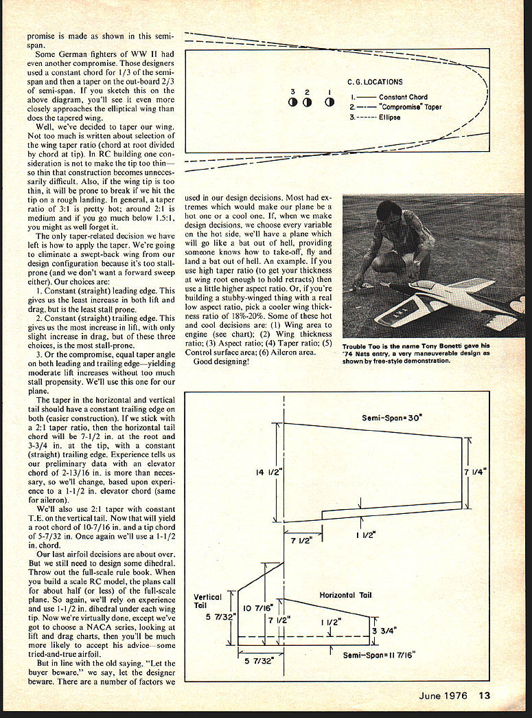
The best planform for taper is the purely elliptical wing of the Supermarine Spitfire. The next best is the semi-elliptical wing of the Thunderbolt. Problem is that both are very costly in full-scale and somewhat more difficult to build in RC. So, the com- promise is made as shown in this semi-span.
Some German fighters of WWII had even another compromise. Those designers used a constant chord for 1/3 of the semi-span and then a taper on the out-board 2/3 of semi-span. If you sketch this on the above diagram, you'll see it even more closely approaches the elliptical wing than does the tapered wing.
Well, we've decided to taper our wing. Not too much is written about selection of the wing taper ratio (chord at root divided by chord at tip). In RC building one consideration is not to make the tip too thin — so thin that construction becomes unnecessarily difficult. Also, if the wing tip is too thin, it will be prone to break if we hit the tip on a rough landing. In general, a taper ratio of 3:1 is pretty hot, around 2:1 is medium and if you go much below 1.5:1, you might as well forget it.
The only taper-related decision we have left is how to apply the taper. We're going to eliminate a swept-back wing from our design configuration because it's too stall-prone (and we don't want a forward sweep either). Our choices are:
- Constant (straight) leading edge. This gives us the least increase in both lift and drag, but is the least stall prone.
- Constant (straight) trailing edge. This gives us the most increase in lift, with only slight increase in drag, but of these three choices, is the most stall-prone.
- Or the compromise, equal taper angle on both leading and trailing edge — yielding moderate lift increases without too much stall propensity. We'll use this one for our plane.
The taper in the horizontal and vertical tail should have a constant trailing edge on both (easier construction). If we stick with a 2:1 taper ratio, then the horizontal tail chord will be 7-1/2 in. at the root and 3-3/4 in. at the tip, with a constant (straight) trailing edge. Experience tells us our preliminary data with an elevator chord of 2-13/16 in. is more than necessary, so we'll change, based upon experience to a 1-1/2 in. elevator chord (same for aileron).
We'll also use 2:1 taper with constant T.E. on the vertical tail. Now that will yield a root chord of 10-7/16 in. and a tip chord of 5-7/32 in. Once again we'll use a 1-1/2 in. chord.
Our last airfoil decisions are about over. But we still need to design some dihedral. Throw out the full-scale rule book. When you build a scale RC model, the plans call for about half (or less) of the full-scale plane. So again, we'll rely on experience and use 1-1/2 in. dihedral under each wing tip. Now we're virtually done, except we've got to choose a NACA series, looking at lift and drag charts, then you'll be much more likely to accept his advice — some tried-and-true airfoil.
But in line with the old saying, "Let the buyer beware," we say, let the designer beware. There are a number of factors we used in our design decisions. Most had extremes which would make our plane be a hot one or a cool one. If, when we make design decisions, we choose every variable on the hot side, we'll have a plane which will go like a bat out of hell, providing someone knows how to take off, fly and land a bat out of hell. An example, If you use high taper ratio (to get your thickness at wing root enough to hold retracts) then use a little higher aspect ratio. Or, if you're building a stubby-winged thing with a real low aspect ratio, pick a cooler wing thickness ratio of 18%-20%. Some of these hot and cool decisions are: (1) Wing area to engine (see chart); (2) Wing thickness ratio; (3) Aspect ratio; (4) Taper ratio; (5) Control surface area; (6) Aileron area. Good designing!
Transcribed from original scans by AI. Minor OCR errors may remain.

