
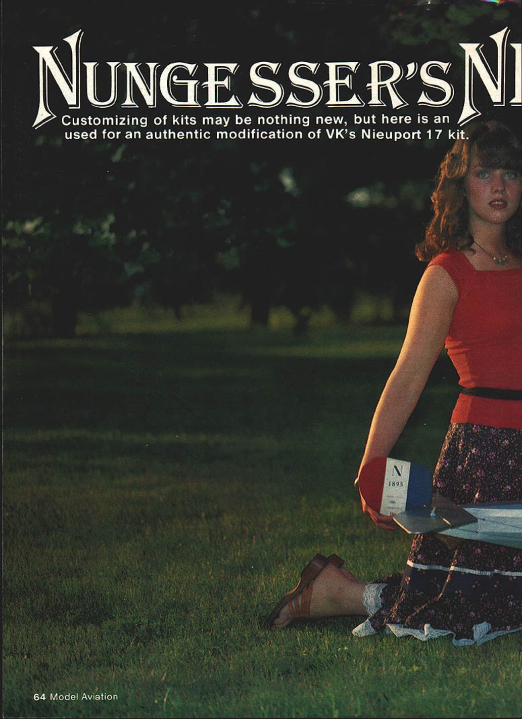
Nungesser's Nieuport 24 BIS
Customizing kits may be nothing new, but here is an approach used for an authentic modification of VK's Nieuport 17 kit. This is an especially charming story of the discovery of a rare Nieuport type by Frank P. Stanton and Edward C. Miller.
Discovery
All true scale nuts are always on the lookout for something different. One summer evening in 1975 George Keis (WB3FFK) called me with a hot tip about a Nieuport lurking in Hangar #1 at the Willow Grove Naval Air Station.
"Aw, come on, George," I protested. "There isn't any such thing around here. You just want to stop at the club, right?"
"No kidding?"
"There really is?"
"OK, George—"
Then it was zap in the batteries in the 35mm SLR and off to go look at George's mysterious apparition.
Arriving at the hangar, sure enough there was an authentic, full-scale Nieuport. Certainly any World War I vintage Nieuport is something to see today, but even more interesting was that this was an extremely rare Nieuport Type 24bis, replete with the macabre death's-head insignia of the famous French ace Charles Nungesser.
As George picked the appropriate angles, I snapped away with the 35. Using a strobe in a dimly lit hangar at night is hard on the eyeballs. After some 30 shots George looked like an owl! After all this flashing in Hangar #1, an SP showed up muttering something about, "What the #$%# is going on?"
We explained to him about the 1917 Nieuport's historic importance. His perceptive reply was, "Well, I guess it's OK, the machine must have been declassified by now."
Controversy and historical context
Even though details concerning the Nieuport Type 24bis are indeed now declassified, certain features still remain shrouded in controversy. Two such points in question are the exact engine and specific markings actually used on Charles Nungesser's 24bis. With much apparently conflicting data and contradictory photographic documentation available, these arguments may never be resolved. Indeed, the true answer may be that they are all correct, merely representing various daily updates under the rigors of continuous combat operations, with no historian present to record each of the changes in their proper chronological sequence.
During the early months of 1916 a rapid sequence of events occurred which would eventually lead to the birth of the Nieuport Type 24bis. During those dark months German Fokkers completely dominated the skies over the Western Front. To counter this German ascendancy, the British rapidly deployed the de Havilland DH-2 pusher fighter, an effective if somewhat ungainly stop-gap aeroplane. The French, on the other hand, found a much more enduring solution to the German threat. The French solution was provided by their nimble Nieuport 17 series of aeroplanes.
Piloting this maneuverable little scout fighter, French aces such as the formidable Nungesser made a significant contribution to regaining Allied aerial superiority. The British Royal Flying Corps (RFC) was quick to recognize the obvious merits of this French design, and soon Nieuport fighters equipped numerous RFC squadrons.
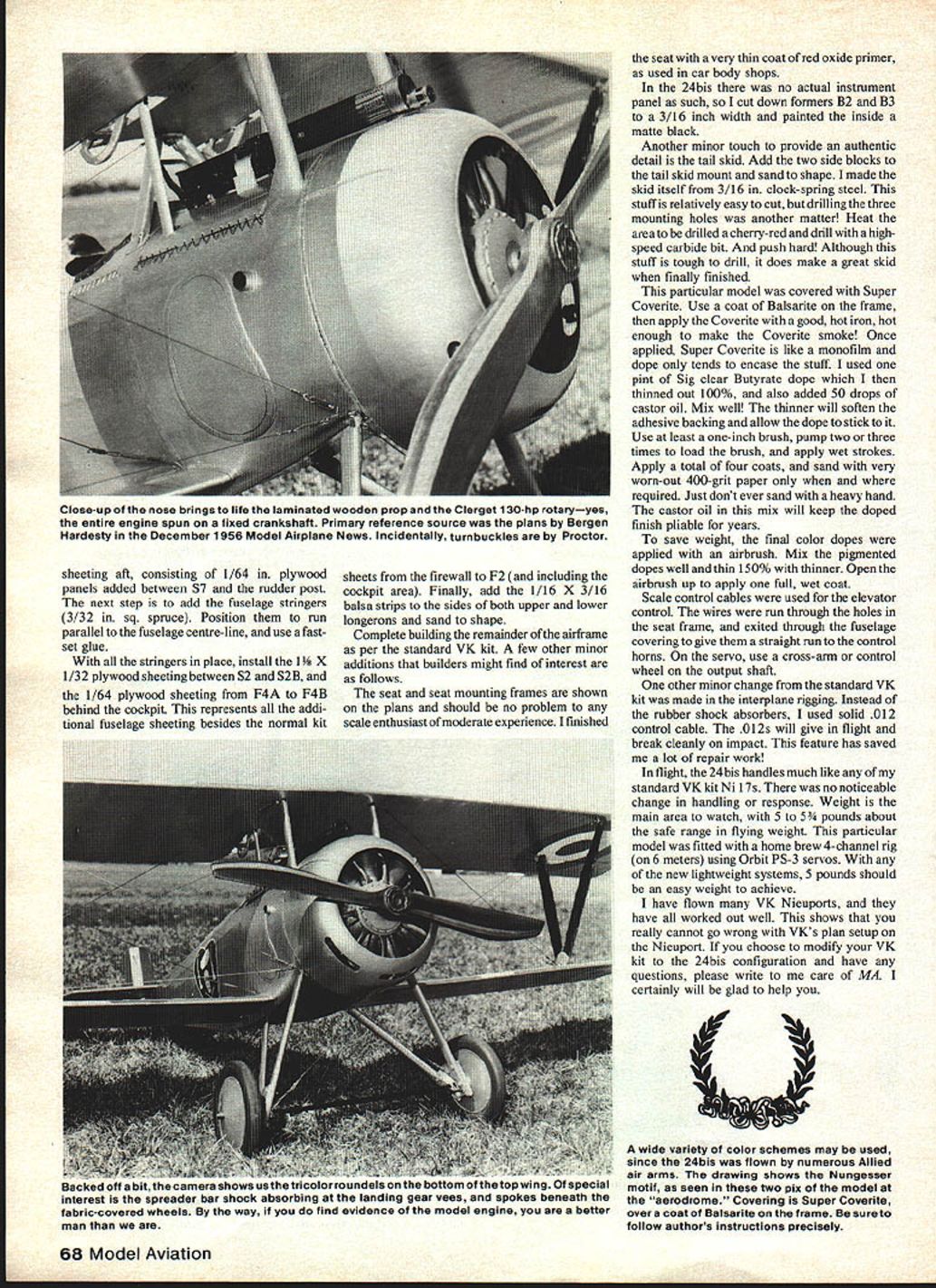
Derived from the earlier Nieuport 11, the Type 17 featured a slightly larger and substantially stronger airframe. It was powered by the 110-hp Le Rhone rotary engine. When subsequently fitted with the 130-hp Clerget engine, it was designated the Nieuport Type 17bis.
With the basic design superiority clearly established by their Type 17bis, the Nieuport design team under Gustave Delage next turned their attention to aerodynamic refinements. To achieve a smoother airflow, the slab-sided fuselage was given a face-lifting by the addition of a series of gently curving formers and stringers. Thus was produced the Nieuport Type 24bis. With its streamlined fuselage, it was the last Nieuport to achieve any degree of notable success in the combat arena. It even eclipsed the standard Type 24, which was plagued with structural problems from its totally new empennage design.
Converting the VK Nieuport 17 kit to a Type 24bis
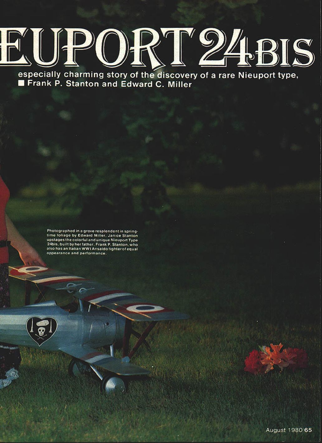
On the market today, VK has produced a beautiful RC kit of the Nieuport 17. With the modifications shown here, the rather boxy Type 17 can be readily converted into a unique model of the much more aesthetic Nieuport Type 24bis. Since the Type 24bis was operated by numerous Allied air arms, a wide variety of markings are available for use on this model. With its rare historic interest and extremely colorful insignia, I selected the Nieuport 24bis flown by Lt. Charles Nungesser for the prototype model seen in the photographs which accompany this article.
The primary reference source for this project is the 1/8-in. scale drawings of the Nieuport Type 24bis by Bergen Hardesty, published in Model Airplane News, December 1956.
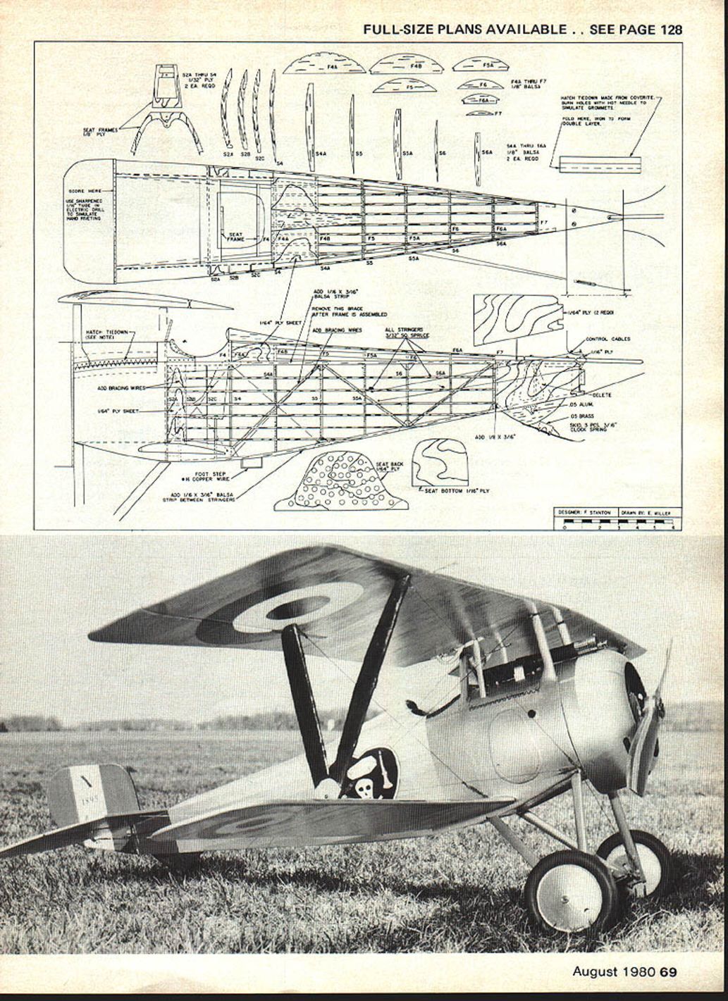
Start the modification program by fabricating the following formers and components:
- From 1/32-in. plywood: S2A, S2B, S2C, S4. Make two of each.
- From 1/8-in. balsa: S4A, S5, S5A, S6, S6A. Make two of each.
- Top turtledeck formers from 1/8-in. balsa: F4A, F4B, F5, F5A, F6, F6A, F7.
These components constitute the basic sub-kit package.
- Build the basic fuselage kit sides over the kit plans. Assemble the basic fuselage box frame assembly, and add all the standard formers from B2 forward.
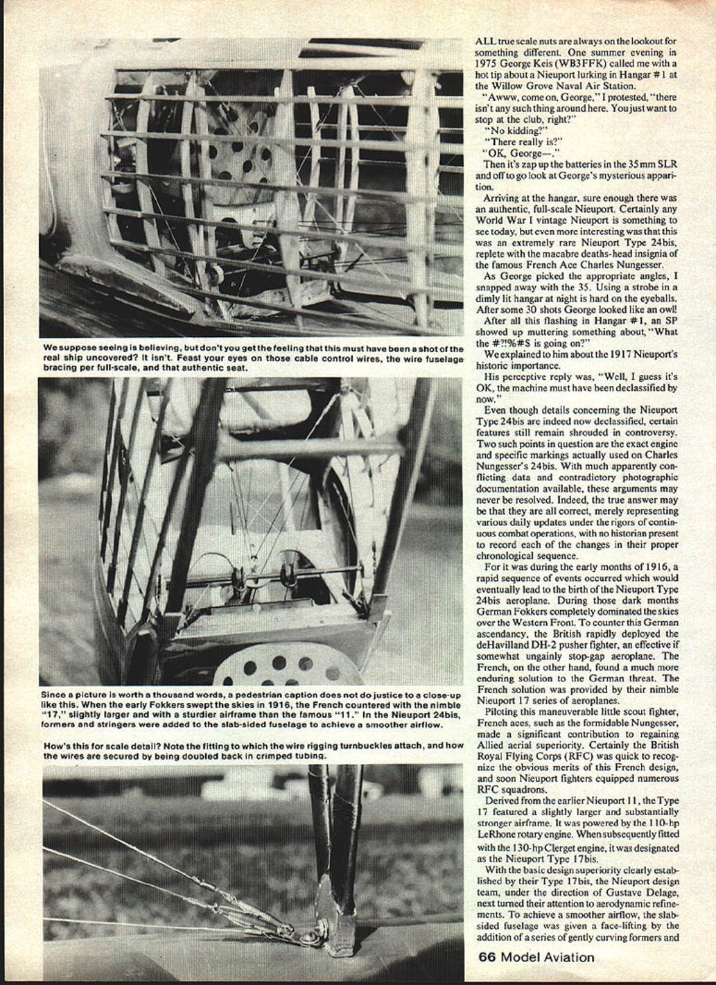
- I added wire diagonal cross-bracing to the inside of the fuselage sides from S2 to S5 (note: remove the kit's 1/16 x 3/16 diagonal wood bracing between lower S4 and upper S5 to facilitate installation of the wire diagonal braces). The only section that can be easily seen is in the cockpit area, so do this area to increase the stand-off scale static judging points.
- If you elect to install wire diagonal braces, make them from .014 control-line cable and use Proctor turnbuckles. See sketch on plans.
- With the internal fuse bracing installed, add the four 1/32-in. plywood formers (S2A through S4) on each side. Finally, add the remaining side formers (S4A through S6) and the top turtledeck formers (F4A through F7).
- Note that the top turtledeck stringer locations are dictated by the notched inserts in former F4A. Don't notch any other formers, as the stringers are positioned and glued on top of the formers.
- Add the fuselage sheeting aft, consisting of 1/64-in. plywood panels added between S7 and the rudder post.
- Add the fuselage stringers (3/32-in. sq. spruce). Position them to run parallel to the fuselage centerline, and use a fast-set glue.
- With all the stringers in place, install:
- 1-1/2 x 1/32-in. plywood sheeting between S2 and S2B.
- 1/64-in. plywood sheeting from F4A to F4B behind the cockpit.
- These represent all additional fuselage sheeting besides the normal kit sheets from the firewall to F2 (and including the cockpit area).
- Finally, add 1/16 x 3/16-in. balsa strips to the sides of both upper and lower longerons and sand to shape.
Complete building the remainder of the airframe as per the standard VK kit. A few other minor additions that builders might find of interest are as follows.
- The seat and seat mounting frames are shown on the plans and should be no problem to any scale enthusiast of moderate experience. I finished the seat with a very thin coat of red oxide primer, as used in car body shops.
- In the 24bis there was no actual instrument panel as such, so I cut down formers B2 and B3 to a 3/16-in. width and painted the inside matte black.
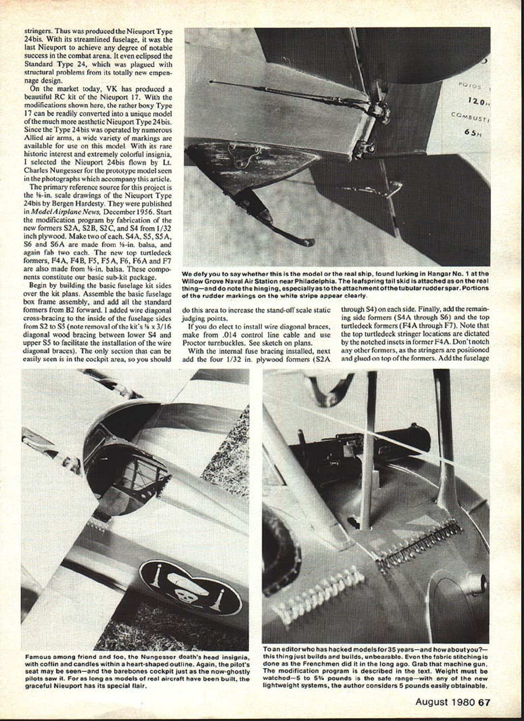
- Another minor touch to provide an authentic detail is the tail skid. Add the two side blocks to the tail skid mount and sand to shape. I made the skid itself from 3/16-in. clock-spring steel. This stuff is relatively easy to cut, but drilling the three mounting holes was another matter! Heat the area to be drilled to a cherry-red and drill with a high-speed carbide bit. Push hard! Although this stuff is tough to drill, it does make a great skid when finally finished.
Covering, finishing and rigging
This particular model was covered with Super Coverite. Use a coat of Balsarite on the frame, then apply the Coverite with a good, hot iron, hot enough to make the Coverite smoke! Once applied, Super Coverite is like a monofilm and dope only tends to encase the stuff.
I used one pint of Sig clear butyrate dope which I then thinned out 100%, and also added 50 drops of castor oil. Mix well. The thinner will soften the adhesive backing and allow the dope to stick to it. Use at least a one-inch brush, pump two or three times to load the brush, and apply wet strokes. Apply a total of four coats, and sand with very worn-out 400-grit paper only when and where required. Just don't ever sand with a heavy hand. The castor oil in this mix will keep the doped finish pliable for years.
To save weight, the final color dopes were applied with an airbrush. Mix the pigmented dopes well and thin 150% with thinner. Open the airbrush up to apply one full, wet coat.
Scale control cables were used for the elevator control. The wires were run through the holes in the seat frame and exited through the fuselage covering to give them a straight run to the control horns. On the servo, use a cross-arm or control wheel on the output shaft.
One other minor change from the standard VK kit was made in the interplane rigging. Instead of the rubber shock absorbers, I used solid .012 control cable. The .012s will give in flight and break cleanly on impact. This feature has saved me a lot of repair work!
Flight characteristics and final notes
In flight, the 24bis handles much like any of my standard VK kit Nieuports. There was no noticeable change in handling or response. Weight is the main area to watch, with 5 to 5-1/2 pounds about the safe range in flying weight. This particular model was fitted with a home-brew 4-channel rig (on 6 meters) using Orbit PS-3 servos. With any of the new lightweight systems, 5 pounds should be an easy weight to achieve.
I have flown many VK Nieuports, and they have all worked out well. This shows that you really cannot go wrong with VK's plan setup on the Nieuport. If you choose to modify your VK kit to the 24bis configuration and have any questions, please write to me care of Model Airplane News. I certainly will be glad to help you.
A wide variety of color schemes may be used, since the 24bis was flown by numerous Allied air arms. The drawing shows the Nungesser motif, as seen in the photographs of the model at the "aerodrome." Covering is Super Coverite over a coat of Balsarite on the frame. Be sure to follow the author's instructions precisely.
Transcribed from original scans by AI. Minor OCR errors may remain.

