
NVCL Dragonfly
Design by Ron McNally and Bob Dorn Text by John Hunton
Background
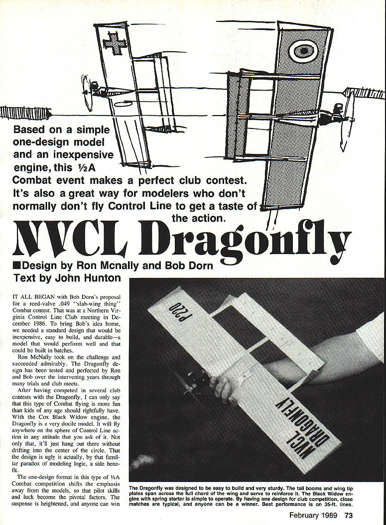
Based on a simple one-design model and an inexpensive engine, this 1/2A Combat event makes a perfect club contest. It's also a great way for modelers who don't normally fly Control Line to get a taste of the action.
It all began with Bob Dorn's proposal for a reed-valve .049 "slab-wing thing" Combat contest at a Northern Virginia Control Line Club meeting in December 1986. To bring Bob's idea home, we needed a standard design that would be inexpensive, easy to build, and durable—a model that would perform well and that could be built in batches.
Ron McNally took on the challenge and succeeded admirably. The Dragonfly design has been tested and perfected by Ron and Bob over the intervening years through many trials and club meets.
After having competed in several club contests with the Dragonfly, I can only say that this type of Combat flying is more fun than kids of any age should rightfully have. With the Cox Black Widow engine, the Dragonfly is a very docile model. It will fly anywhere on the sphere of Control Line action in any attitude that you ask of it. Not only that, it will just hang out there without drifting into the center of the circle. That the design is ugly is actually, by that familiar paradox of modeling logic, a side benefit.
The one-design format in this type of 1/2A Combat competition shifts the emphasis away from the models, so pilot skills and luck become the pivotal factors. The suspense is heightened, and anyone can be a winner. Best performance is on 35 ft. lines.
At one meet I personally competed in, ferocious Combat action continued until the models suddenly met in midair and spun in. Although the accident knocked both motors off their mounts, with the help of cyanoacrylate (CyA) and accelerator both models were back in the air and locked in mortal combat again within the five-minute time limit.
Construction
The Dragonfly can be built very quickly. It's not a particularly demanding project as to either workmanship or finish.
- Glue all airframe parts together with CyA.
- Assemble all engine-mount parts with epoxy.
- Before final assembly, sand all parts to shape and prepare for finishing.
Engine preparation and mounting
The Cox Black Widow and Golden Bee engines both have stunt-type tanks which will run when inverted. Bolt your engine to the firewall with nuts to the rear. Dig out the balsa fairings to clear the nuts (sheet metal screws can be used also), then epoxy the engine mount in place.
After the epoxy has cured completely, remove the engine and prepare it as follows:
- Clean the engine thoroughly by immersing it in alcohol or other water-free solvent.
- Remove the fuel tank and backplate.
- Reassemble the engine with:
- the cylinder head to the outside of the circle,
- the tank vents in the up/down position (but toward the inside of the circle),
- the backplate with the needle valve positioned in the same direction as the cylinder (toward the outside of the circle).
The only complication this configuration presents is that the standard fuel line pickup will not be suitable. Use a piece of small silicon tubing to form a tight "U" shape with the stock spring inside. A piece of fine copper wire holds the loop's shape. Cut the tubing so that one end will fit on the fuel-feed nipple and the other end will lay on the inside surface of the tank as close as possible to the outside of the circle. Cut an angle on the pickup end of the tube. Check that the small rubber gasket on the venturi is in place and healthy (the engine will not run without this gasket), then reassemble the engine.
Finishing and final assembly
Finish all parts of the model with fuel-proof dope (light) or polyurethane. The latter may be clear, in which case it is fairly light, or color (heavy).
- Sew the elevator to the stabilizer with dental floss, and glue the knobs.
- Install a 1/4" bellcrank and control horn, then install the pushrod and lead-outs.
- Put two pennies in the outboard tip and tape them into place. More pennies can be added later to improve line tension, if necessary.
When the finish is dry, reinstall the engine. Place a couple of washers under the noseboard engine-mount screws to create thrust. Be sure the cylinder is toward the outboard (right) side.
Balance the model to the point shown on the plan.
Flying
Northern Virginia Control Line Club rules require that the Dragonfly utilize .012-in. thick braided lines at 35 ft. length. Use a control handle with a 2- to 2-1/2-in. spread (increasing the spread beyond that point will create oversensitivity).
For your initial flights be sure to hold neutral control upon launch (not full up). If you want your model to be less vulnerable to destruction, it is recommended that you fly it over grass at all times. The higher the grass, the more likely you are to avert demolition.
See the AMA rule book for guidelines on how to set up a Combat match. Practice Combat maneuvers in solo flight and be prepared to tear the tail off your opponent.
Transcribed from original scans by AI. Minor OCR errors may remain.

