
Ole Reliable
Sam Snyder
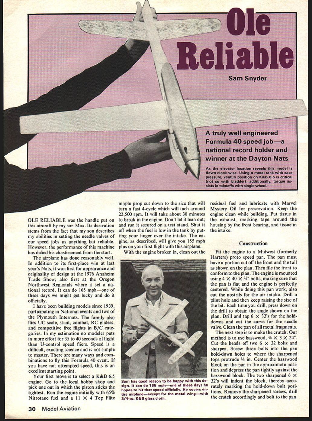
OLE RELIABLE was the handle put on this aircraft by my son Max. Its derivation stems from the fact that my son describes my abilities in setting the needle valves of our speed jobs as anything but reliable. However, the performance of this machine has defied his chastisement from the start.
The airplane has done reasonably well. In addition to its first-place win at last year's Nats, it won first for appearance and originality of design at the 1976 Anaheim Trade Show; also first at the Oregon Northwest Regionals where it set a national record. It can do 165 mph—one of these days we might get lucky and do it officially.
I have been building models since 1939, participating in National events and two of the Plymouth Internats. The family also flies UC scale, stunt, combat, RC gliders, and competitive free flights in B/C categories. In my estimation no modeler puts in more effort for 35 to 40 seconds of flight than U-control speed fliers. Speed is a difficult, exacting science and is not simple to master. There are many ways and combinations to fly this Formula 40 event. If you have not attempted speed, this is an excellent starting point.
Your first move is to select a K&B 6.5 engine. Go to the local hobby shop and pick one out in which the piston sticks the tightest. Run the engine initially with 65% Nitrotane fuel and an 11 X 4 Top Flite maple prop cut down to the size that will turn a fast 4-cycle which will tach around 22,500 rpm. It will take about 30 minutes to break in the engine. Don't let it lean out; and run it secured on a test stand. Shut it off when the fuel is low in the tank by putting your finger over the intake. The engine, as described, will give you 155 mph plus on your first flight with this airplane.
With the engine broken in, clean out the residual fuel and lubricate with Marvel Mystery Oil for preservation. Keep the engine clean while building. Put tissue in the exhaust, masking tape around the housing by the front bearing, and tissue in the intake.
Construction
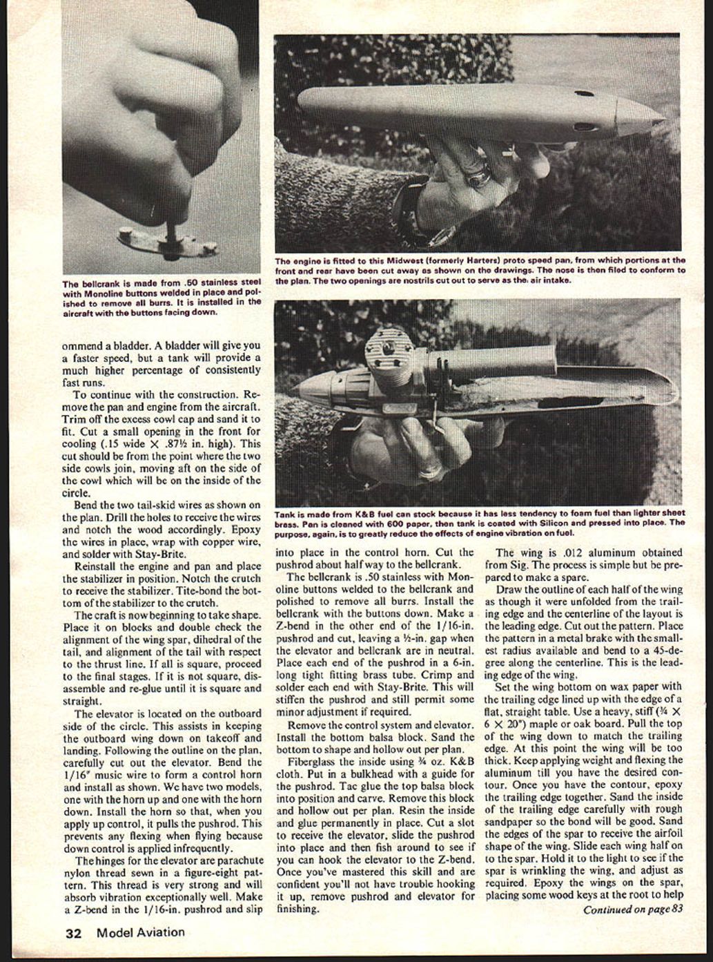
Fit the engine to a Midwest (formerly Harters) proto speed pan. The pan must have a portion cut off the front and the tail as shown on the plan. Then file the front to conform to the plan. The engine is mounted using 4 X 40 X 3/4" bolts, making sure that the pan is flat and the engine is perfectly centered. While doing this pan work, also cut the nostrils for the air intake. Drill a pilot hole and then keep raising the size of the bit. Each time you drill, press down on the drill to obtain the angle shown on the plan. Drill and tap 6 X 32's for the holddowns and cut the curve for the needle valve. Clean the pan of all metal fragments.
The next step is to make the crutch. Our method is to use basswood, 3/8" X 3" X 24". Cut the heads off two 6 X 32 bolts and sharpen. Screw these bolts into the pan hold-down holes to where the sharpened tops protrude 1/8". Center the basswood block on the pan in the approximate position and depress the pan tightly against the basswood block. The two sharpened 6 X 32's will indent the block, thereby accurately marking the hold-down bolt positions. Remove the sharpened screws, drill the crutch accordingly and bolt to the pan.
Now scribe the basswood around the pan so it will fit accurately. Take the pan off the crutch and transfer the remaining outline from the crutch top view on the plans. Carefully cut out the crutch inside and outside. Cut out a second basswood crutch the same size. Cut out the outside point and you now have two 3/8-in. basswood crutches to fit the pan. Put the crutches aside.
Using a piece of very straight maple, wide, 3/8" thick, cut out the wing spar shown on the plan. Spar is flat on top, tapered on bottom to 3/16" at the tips. Now comes the tricky part. Center the spar perfectly over the crutch hold-down holes. Drill holes through the spar. Using two long 6 X 32 bolts place the spar between the two crutches and bolt together. Scribe the bottom crutch along the spar front and back. Unbolt the crutch and cut the bottom crutch along the scribe lines.
Recap: you now have a true crutch complete, the spar complete, and two pieces of bottom crutch—the front piece goes to the front spar, the aft piece goes to the back spar tail. Noting where plan balsa begins and ends, cut back the bottom crutch accordingly. Still can't glue anything together yet because 6 X 32 blind-nuts, maple spar, bellcrank, 4 X 40 nut plate and stainless steel landing gear must be installed.
After cutting the landing gear flat, drill two bolt holes for mounting and drill a 4 X 40 hole for the axle. Grip the top of the gear in a vise and bend the 1/8" end 90 degrees. Bolt the gear to the front bottom crutch offset enough from the centerline to clear the mini-pipe inside circle. During takeoff this insures the outboard wing is tilted down; also tail V.D. can't drag in the wing-down position on takeoff and landing. The preceding steps make assembly an easy job. Bolt the wing spar top portion to the crutch using the bellcrank bolt and the pan hold-down bolts. Glue with Titebond, put vaseline on the bolts and periodically turn to insure they are not bound. Glue the position of the front bottom crutch and the gear using clamps.
Sam has good reason to be happy with this design. It can do 165 mph—one of those days he hopes to hit that speed officially. He covers the entire airplane—except for the metal wing—with 3/4-oz. K&B glass cloth. Now scribe the basswood around the pan so it will fit accurately. Take the pan off the crutch and transfer the remaining outline for the crutch from the top view of the plans. Carefully cut out the crutch, inside and outside. When cut out, trace the crutch on to another piece of basswood the same size. Cut it out on the outside only. At this point you now have two 3/8-in. basswood crutches that fit the pan. Put the crutches aside.
Using a piece of very straight maple, 1/2 in. wide by 3/8 in. thick, cut out the wing spar as shown on the plan. The spar is flat on top and tapered from the bottom to 3/16 in. at the tips. Now comes the tricky part. Center the spar perfectly over the crutch hold-down holes. Drill the holes through the spar. Using two long 6 X 32 bolts, place the spar in between the two crutches and bolt it together. Scribe the bottom crutch along the spar front and back. Unbolt the crutch and cut the bottom crutch along these scribe lines.
To recap, we have the true crutch complete in length, the spar complete and two pieces of bottom crutch—the front piece that goes in front of the spar, and the aft piece that goes in back of the spar to the tail. Noting the plan where balsa begins and where it ends, cut this back bottom crutch accordingly.
We still can't glue anything together yet because the 6 X 32 blind-nut in the maple spar for the bellcrank and the 4 X 40 nut plate for the stainless steel landing gear must be installed. After cutting the landing gear flat with the two bolt holes for mounting, drill the 4 X 40 hole for the axle. Grip the top of the gear in a vise 4 in. from the end and bend to 90-degree angle. Bolt the gear to the front bottom crutch, offset enough from the centerline to clear the mini-pipe, and to the inside of the circle. During takeoff, this insures that the outboard wing is tilted down. This also is why the tail is V'd, so that it can't drag in the wing-down position on takeoff or landing.
The preceding steps make assembly an easy job.
Bolt the wing spar to the top portion of the crutch using the bellcrank bolt and the pan hold-down bolts. Glue with Titebond; put vaseline on the bolts and periodically turn them to insure they are not bound. Glue in position the front bottom crutch with the gear. Using clamps, glue the aft bottom crutch pieces into position. Using basswood 3/16 in. thick, cut a slot for the landing gear and glue on as a cap over the bottom crutch, wing spar and aft crutch adjacent to the wing spar.
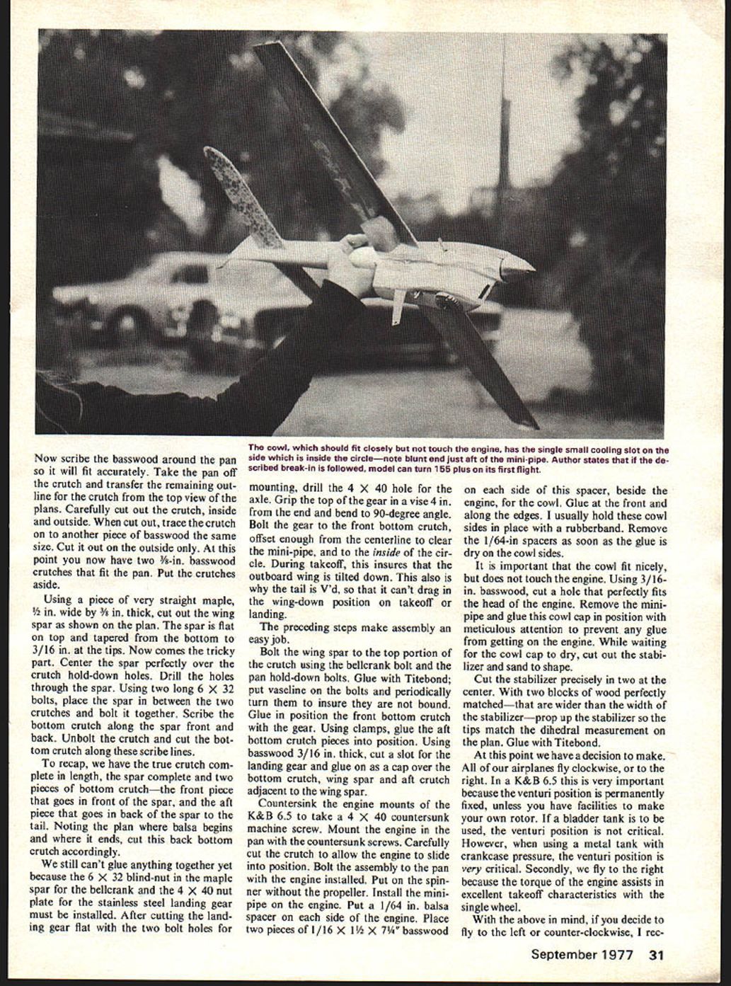
Countersink the engine mounts of the K&B 6.5 to take a 4 X 40 countersunk machine screw. Mount the engine in the pan with the countersunk screws. Carefully cut the crutch to allow the engine to slide into position. Bolt the assembly to the pan with the engine installed. Put on the spinner without the propeller. Install the mini-pipe on the engine. Put a 1/64-in. balsa spacer on each side of the engine. Place two pieces of 1/16 X 1 1/2 X 7 1/4 basswood on each side of this spacer, beside the engine, for the cowl. Glue at the front and along the edges. I usually hold these cowl sides in place with a rubberband. Remove the 1/64-in. spacers as soon as the glue is dry on the cowl sides.
It is important that the cowl fit nicely, but does not touch the engine. Using 3/16-in. basswood, cut a hole that perfectly fits the head of the engine. Remove the mini-pipe and glue this cowl cap in position with meticulous attention to prevent any glue from getting on the engine. While waiting for the cowl cap to dry, cut out the stabilizer and sand to shape.
Cut the stabilizer precisely in two at the center. With two blocks of wood perfectly matched—that are wider than the width of the stabilizer—prop up the stabilizer so the tips match the dihedral measurement on the plan. Glue with Titebond.
At this point we have a decision to make. All of our airplanes fly clockwise, or to the right. In a K & B 6.5 this is very important because the venturi position is permanently fixed, unless you have facilities to make your own rotor. If a bladder tank is to be used, the venturi position is not critical. However, when using a metal tank with crankcase pressure, the venturi position is very critical. Secondly, we fly to the right because the torque of the engine assists in excellent takeoff characteristics with the single wheel.
With the above in mind, if you decide to fly to the left or counter-clockwise, I rec- recommend a bladder. A bladder will give you a faster speed, but a tank will provide a much higher percentage of consistently fast runs.
To continue with the construction, remove the pan and engine from the aircraft. Trim off the excess cowl cap and sand it to fit. Cut a small opening in the front for cooling (.15 in. wide x .87 in. high). This cut should be from the point where the two side cowls join, moving aft on the side of the cowl which will be on the inside of the circle.
Bend the two tail-skid wires as shown on the plan. Drill the holes to receive the wires and notch the wood accordingly. Epoxy the wires in place, wrap with copper wire, and solder with Stay-Brite.
Reinstall the engine and pan and place the stabilizer in position. Notch the crutch to receive the stabilizer. Titebond the bottom of the stabilizer to the crutch.
The craft is now beginning to take shape. Place it on blocks and double check the alignment of the wing spar, dihedral of the tail, and alignment of the tail with respect to the thrust line. If all is square, proceed to the final stages. If it is not square, disassemble and re-glue until it is square and straight.
The elevator is located on the outboard side of the circle. This assists in keeping the outboard wing down on takeoff and landing. Following the outline on the plan, carefully cut out the elevator. Bend the 1/16" music wire to form a control horn and install as shown. We have two models, one with the horn up and one with the horn down. Install the horn so that, when you apply up control, it pulls the pushrod. This prevents any flexing when flying because down control is applied infrequently.
The hinges for the elevator are parachute nylon thread sewn in a figure-eight pattern. This thread is very strong and will absorb vibration exceptionally well. Make a Z-bend in the 1/16-in. pushrod and slip into place in the control horn. Cut the pushrod about halfway to the bellcrank.
The bellcrank is .50 stainless with Monoline buttons welded to the bellcrank and polished to remove all burrs. Install the bellcrank with the buttons down. Make a Z-bend in the other end of the 1/16-in. pushrod and cut, leaving a 1/4-in. gap when the elevator and bellcrank are in neutral. Place each end of the pushrod in a 6-in. long tight-fitting brass tube. Crimp and solder each end with Stay-Brite. This will stiffen the pushrod and still permit some minor adjustment if required.
Remove the control system and elevator. Install the bottom balsa block. Sand the bottom to shape and hollow out per plan.
Fiberglass the inside using 1/8 oz. K&B cloth. Put in a bulkhead with a guide for the pushrod. Tac-glue the top balsa block into position and carve. Remove this block and hollow out per plan. Resin the inside and glue permanently in place. Cut a slot to receive the elevator, slide the pushrod into place and then fish around to see if you can hook the elevator to the Z-bend. Once you've mastered this skill and are confident you'll not have trouble hooking it up, remove pushrod and elevator for finishing.
Fit the engine to the Midwest (formerly Harters) proto speed pan. The pan must have the front and rear portions cut off as shown on the plan. File the nose to conform to the plan. While doing pan work, also cut the nostrils for the air intake. Drill a pilot hole and keep raising the size of the bit; use the drill press to obtain the angle shown on the plan. Drill and tap 6-32s for the holddowns. Clean the pan of metal fragments.
Next step is to make the crutch. Use basswood 3/4 x 2-1/4 (approx.). Cut the heads off two 6-32 bolts and sharpen the screw ends. Place the bolts in the pan hold-down holes; the sharpened tops should protrude. Center the basswood block on the pan and depress the pan tightly against the basswood block. The two sharpened 6-32s will indent the block, thereby accurately marking the hold-down bolt positions. Remove the sharpened screws, drill the crutch accordingly and bolt the pan in place.
Now scribe the basswood around the pan so it will fit accurately. Take the pan off the crutch and transfer the remaining outline from the crutch top view to the plans. Carefully cut out the crutch inside and outside. Trace the crutch on another piece of basswood the same size and cut out the outside point so you now have two 3/8-in. basswood crutches to fit the pan. Put the crutches aside.
Using a piece of very straight maple, about 3/4 in. wide and 3/16 in. thick, cut out the wing spar shown on the plan. The spar should be flat on top and tapered on the bottom to 3/16 in. at the tips.
Now comes the tricky part. Center the spar perfectly over the crutch hold-down holes. Drill holes through the spar. Using two long 6-32 bolts, place the spar between the two crutches and bolt together. Scribe the bottom crutch along the spar front and back. Unbolt the crutch and cut the bottom crutch along the scribe lines. Recap: you have a true crutch of complete length, spar complete, and two pieces of bottom crutch—the front piece goes on the front spar, the aft piece goes on the back spar tail. Note the plan; balsa begins and ends—cut back the bottom crutch accordingly.
You still can't glue anything together yet because 6-32 blind nuts, the maple spar, bellcrank, 4-40 nut plate, stainless steel landing gear must be installed. After cutting the landing gear flat, drill the two bolt holes for mounting and drill a 4-40 hole for the axle. Grip the top of the gear in a vise and bend the end 90 degrees. Bolt the gear to the front bottom crutch offset enough from the centerline to clear the mini-pipe inside circle. During takeoff this ensures the outboard wing is tilted down; also the tail skid can't drag in the wing-down position on takeoff and landing. The preceding steps make assembly an easy job.
Bolt the wing spar top portion to the crutch using the bellcrank bolt and the pan hold-down bolts. Glue with Titebond; put vaseline on the bolts and periodically turn to ensure they do not bind. Glue the position of the front bottom crutch and gear. Using clamps, glue and let set.
The wing is .012 aluminum obtained from Sig. The process is simple but be prepared to make a spare.
Draw the outline of each half of the wing as though it were unfolded from the trailing edge and the centerline of the layout is the leading edge. Cut out the pattern. Place the pattern in a metal brake with the smallest radius available and bend to a 45-degree edge along the centerline. This is the leading edge of the wing.
Set the wing bottom on wax paper with the trailing edge lined up with the edge of a flat, straight table. Use a heavy, stiff (1/4 x 6 x 20") maple or oak board. Pull the top of the wing down to match the trailing edge. At this point the wing will be too thick. Keep applying weight and flexing the aluminum until you have the desired contour. Once you have the contour, epoxy the trailing edge together. Sand the inside of the trailing edge carefully with rough sandpaper so the bond will be good. Sand the edges of the spar to receive the airfoil shape of the wing. Slide each wing half on to the spar. Hold it to the light to see if the spar is wrinkling the wing, and adjust as required. Epoxy the wings on the spar, placing some wood keys at the root to help finish.
Ole Reliable
Secure it. Cut a small balsa rib and recess it in the tip (1/8 in.) and fill the tips with epoxy. File to shape.
Don't forget to allow for the slots for the control lines and their respective locations on the plan. I position two 1/32-in. dowels in the positions of the control lines, then put vaseline on them at the key points, so that the epoxy can't fill up or block the holes. After the epoxy dries I slide out the dowels.
The aircraft is now ready to finish. Glass cloth the entire airplane (except the aluminum wing) with 3/4-oz. K&B. At the wing joints I place masking tape about 1/2 in. out from the fuselage. Then, with 2-oz. glass cloth I build a fillet top and bottom, feathering it to the aluminum, then remove the tape. This strengthens the joint and smooths the air flow.
After applying the resin, install the elevator, hinges and pushrod. Spray with K&B Super-Poxy primer. Sand with 400 grit and then apply K & B Super-Poxy color. Polish the aluminum wings.
I should like to thank the following persons who, over the years, have assisted me: Bill Wisniewski, Jim Nightengale, Cliff Telford, Luke Roy, John Newton, and George Aldrich. Although everything in this machine is original, from the design through the powerplant modification, their experience and pertinent suggestions in the past have made the current results possible.
Transcribed from original scans by AI. Minor OCR errors may remain.

