
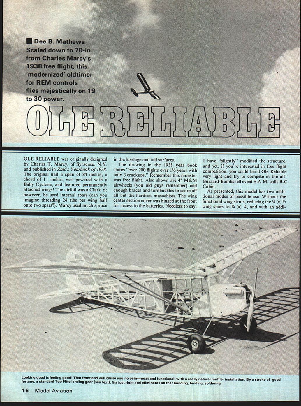
OLE RELIABLE
OLE RELIABLE was originally designed by Charles T. Marcy, of Syracuse, N.Y., and published in Zaic's Yearbook of 1938. The original had a span of 84 inches, a chord of 11 inches, was powered with a Baby Cyclone, and featured permanently attached wings! The airfoil was a Clark Y; however, he used internal spars (can you imagine threading 24 ribs per wing half onto two spars?). Marcy used much spruce in the fuselage and tail surfaces.
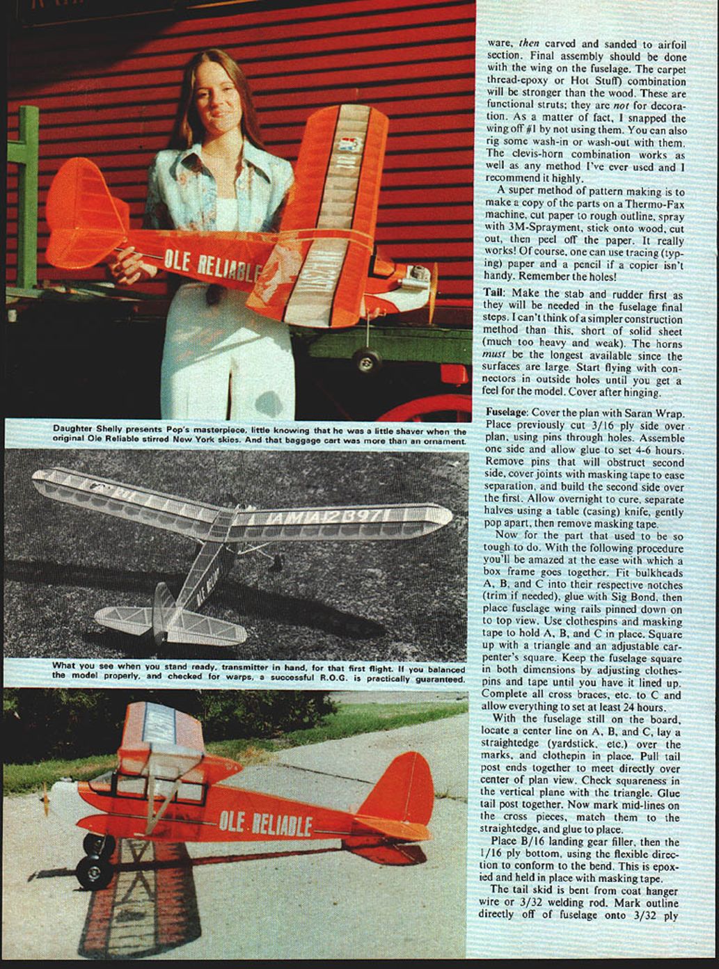
The drawing in the 1938 year book states "over 200 flights over 1½ years with only 3 crackups." Remember this monster was free flight. Also shown are 4" M&M airwheels (you old guys remember) and enough braces and turnbuckles to scare off all but the hardiest masochists. The wing center section cover was hinged at the front for access to the batteries. Needless to say,
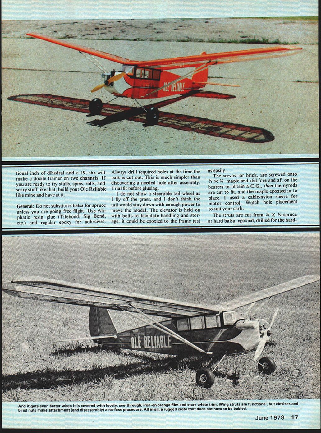
I have "slightly" modified the structure, and yet, if you're interested in free flight competition, you could build Ole Reliable very light and try to compete in the all-Buzzard-Bombshell event S.A.M. calls B-C Cabin.
As presented, this model has two additional modes of possible use. Without the functional wing struts, reducing the 1/4 x 1/2 wing spars to 1/4 x 1/4, and with an additional additional inch of dihedral and a 1/2, she will make a docile trainer on two channels. If you are ready to try stalls, spins, rolls, and scary stuff like that, build your Ole Reliable like mine and have at it.
General: Do not substitute balsa for spruce unless you are going free flight. Use Aliphatic resin glue (Titebond, Sig Bond, etc.) and regular epoxy for adhesives.
Always drill required holes at the time the part is cut out. This is much simpler than discovering a needed hole after assembly. Trial fit before gluing.
I do not show a steerable tail wheel as I fly off the grass, and I don't think the tail would stay down with enough power to move the model. The elevator is held on with bolts to facilitate handling and storage; it could be epoxied to the frame just as easily.
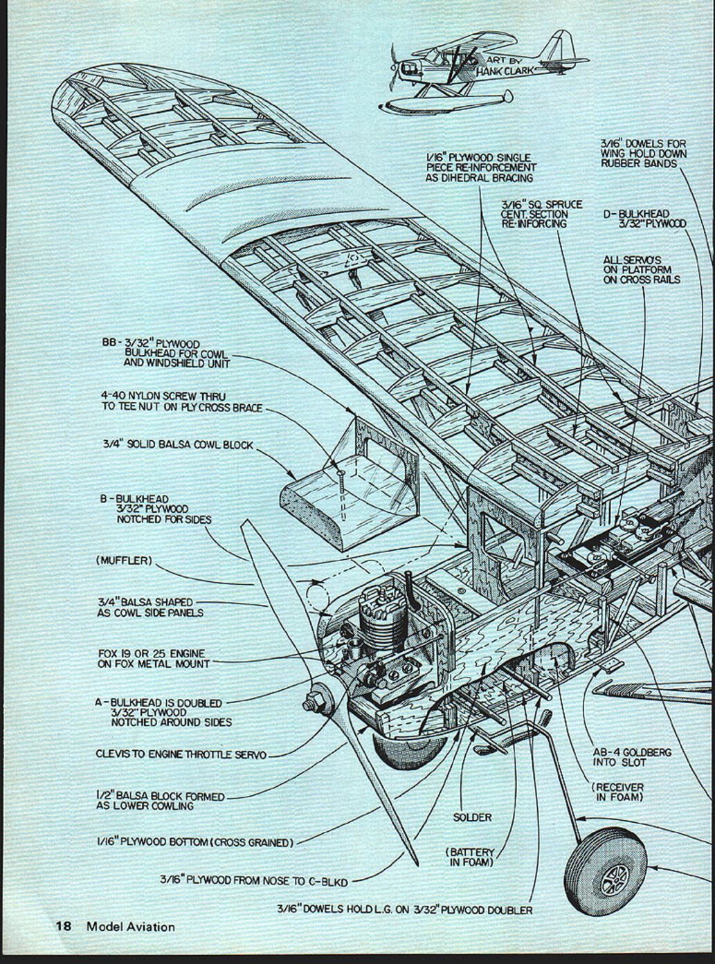
The servos, or brick, are screwed onto 3/8 X 3/8 maple and slid fore and aft on the bearers to obtain a C.G., then the nyrods are cut to fit, and the maple epoxied in to place. I used a cable-nylon sleeve for motor control. Watch hole placement to suit your carb.
The struts are cut from 1/4 X 1/2 spruce or hard balsa, epoxied, drilled for the hardware. BB - 3/32" PLYWOOD BULKHEAD FOR COWL AND WINDSHIELD UNIT
4-40 NYLON SCREW THRU TO TEE NUT ON PLY CROSS BRACE
3/4" SOLID BALSA COWL BLOCK
B - BULKHEAD 3/32" PLYWOOD NOTCHED FOR SIDES
(MUFFLER)
3/4" BALSA SHAPED AS COWL SIDE PANELS
FOX 19 OR 25 ENGINE ON FOX METAL MOUNT
A - BULKHEAD IS DOUBLED 3/32" PLYWOOD NOTCHED AROUND SIDES
CLEVIS TO ENGINE THROTTLE SERVO
1/2" BALSA BLOCK FORMED AS LOWER COWLING
1/16" PLYWOOD BOTTOM (CROSS GRAINED)
3/16" PLYWOOD FROM NOSE TO C-BLKHD
3/16" DOWELS HOLD L.G. ON 3/32" PLYWOOD DOUBLER
1/16" PLYWOOD SINGLE PIECE REINFORCEMENT AS DIHEDRAL BRACING
3/16" SQ. SPRUCE CENT. SECTION RE-INFORCING
3/16" DOWELS FOR WING HOLD DOWN RUBBER BANDS
D - BULKHEAD 3/32" PLYWOOD
ALL SERVOS ON PLATFORM ON CROSS RAILS
CLEVIS ON THREADED ROD
3/8" SQ. MAPLE MAIN RAILS AND CROSS RAILS
AB - 4 GOLDBERG INTO SLOT
AILERON HORN AB-4 PUSHROD B CLEVIS 3/32" MUSIC WIRE
SOLDER
(BATTERY IN FOAM)
(RECEIVER IN FOAM)
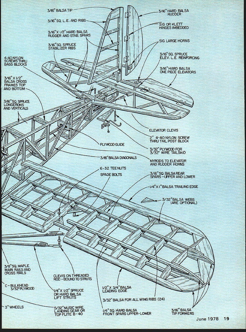
- 3/16" BALSA TIP
- 3/16" SQ. L.E. AND RIBS
- 3/16" X 1/2" HARD BALSA RUDDER AND STAB. SPARS
- 3/16" SQ. SPRUCE STABILIZER RIBS
- 3/16" HARD BALSA RUDDER
- SIG OR KLETT HINGES IMBEDDED
- SIG LARGE HORNS
- 3/16" SQ. SPRUCE ELEV. L.E. REINFORCING
- 3/16" HARD BALSA ONE PIECE ELEVATORS
- ELEVATOR CLEVIS
- 2" 4-40 NYLON SCREW THRU TAIL POST BLOCK
- 3/32" PLYWOOD FOR 3/32" WIRE TAILSKID
- NYRODS TO ELEVATOR AND RUDDER HORNS
- 3/16" SQ. BALSA REAR SPARS - UPPER AND LOWER
- 1/4" X 1" BALSA TRAILING EDGE
- 3/32" BALSA WEBS (ARE OPTIONAL)
- 3/16" BALSA DIAGONALS
- PLYWOOD GUIDE
- 6-32 TEE NUTS
- SPADE BOLTS
- 3/32" BALSA FOR ALL WING RIBS (24)
- 1/2" X 3/4" BALSA LEADING EDGE
- 1/4" SQ. HARD BALSA FRONT SPARS UPPER-LOWER
- 3/16" BALSA TIP FORMERS
- 4-40 NYLON SCREWS THRU BASS BLOCKS
- 3/16" X 1/2" BALSA CROSS FRAMES TOP AND BOTTOM
- 3/16" SQ. SPRUCE LONGERONS AND VERTICALS
- 3/8" SQ. MAPLE MAIN RAILS AND CROSS RAILS
- C - BULKHEAD 3/32" PLYWOOD
- 3" WHEELS
- 5/32" MUSIC WIRE LANDING GEAR OR TOP FLITE B-40
- CLEVIS ON THREADED ROD - BOUND TO STRUTS
- 1/4" X 1/2" SPRUCE OR HARD BALSA LIFT STRUTS
ware, then carved and sanded to airfoil section. Final assembly should be done with the wing on the fuselage. The carpet thread-epoxy or Hot Stuff combination will be stronger than the wood. These are functional struts; they are not for decoration. As a matter of fact, I snapped the wing off #1 by not using them. You can also rig some wash-in or wash-out with them. The clevis-horn combination works as well as any method I've ever used and I recommend it highly.
A super method of pattern making is to make a copy of the parts on a Thermo-Fax machine, cut paper to rough outline, spray with 3M-Sprayment, stick onto wood, cut out, then peel off the paper. It really works! Of course, one can use tracing (typing) paper and a pencil if a copier isn't handy. Remember the holes!
Tail: Make the stab and rudder first as they will be needed in the fuselage final steps. I can't think of a simpler construction method than this, short of solid sheet (much too heavy and weak). The horns must be the longest available since the surfaces are large. Start flying with connectors in outside holes until you get a feel for the model. Cover after hinging.
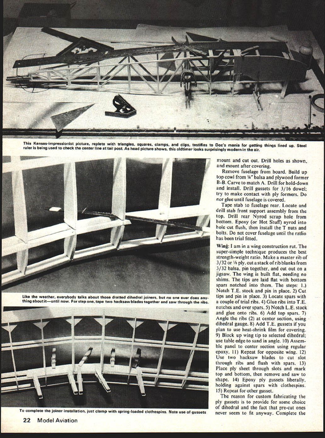
Fuselage: Cover the plan with Saran Wrap. Place previously cut 3/16 ply side over plan, using pins through holes. Assemble one side and allow glue to set 4-6 hours. Remove pins that will obstruct second side, cover joints with masking tape to ease separation, and build the second side over the first. Allow overnight to cure, separate halves using a table (casing) knife, gently pop apart, then remove masking tape.
Now for the part that used to be so tough to do. With the following procedure you'll be amazed at the ease with which a box frame goes together. Fit bulkheads A, B, and C into their respective notches (trim if needed), glue with Sig Bond, then place fuselage wing rails pinned down on to top view. Use clothespins and masking tape to hold A, B, and C in place. Square up with a triangle and an adjustable carpenter's square. Keep the fuselage square in both dimensions by adjusting clothespins and tape until you have it lined up. Complete all cross braces, etc., to C and allow everything to set at least 24 hours.
With the fuselage still on the board, locate a center line on A, B, and C, lay a straightedge (yardstick, etc.) over the marks, and clothespin in place. Pull tail post ends together to meet directly over center of plan view. Check squareness in the vertical plane with the triangle. Glue tail post together. Now mark mid-lines on the cross pieces, match them to the straightedge, and glue to place.
Place B/16 landing gear filler, then the 1/16 ply bottom, using the flexible direction to conform to the bend. This is epoxied and held in place with masking tape.
The tail skid is bent from coat hanger wire or 3/32 welding rod. Mark outline directly off of fuselage onto 3/32 ply
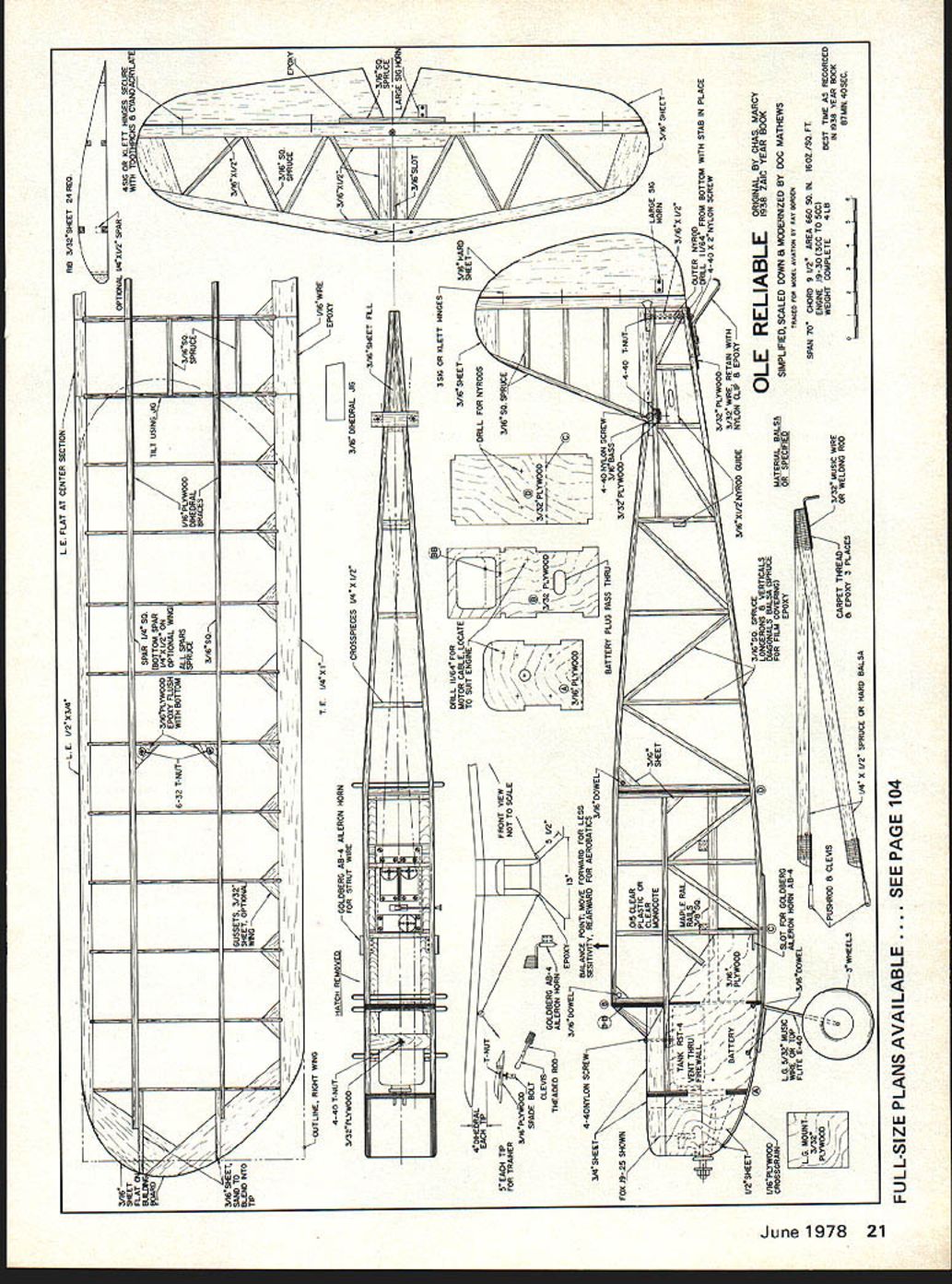
OLE RELIABLE
SIMPLE, SCALED DOWN & MODERNIZED BY CHAS. MARCY ORIGINAL DESIGN BY DOC MATHEWS TRACED FOR MODEL AVIATION BY RAY WZARCCN
SPAN 70" CHORD 10" AREA 1602 SQ. IN. LENGTH 52" ENGINE: FOX .19 OR FOX .35 FULL-SIZE PLANS AVAILABLE ... SEE PAGE 104
L.E. FLAT AT CENTER SECTION
RIBS: 3/32" SHEET — 24 REQ. (OPTIONAL) 1/4" x 1/2" SPAR 3/16" PLYWOOD SPAR USE SIG OR KLETT HINGES SECURE HINGES WITH CYANOACRYLATE 3/16" PLYWOOD SPAR BOTTOM SPAR — LIFT USING JIG 1/4" x 1/2" spar on tie-rod epoxy plush optional wing 22 T.NUT WITH BOTTOM ON ALL SPARS SPRUCE GUSSETS 3/32" PLYWOOD; BLEND INTO SHEET AT TIP WING 3/16" SPRUCE — EPOXY IN LINE RIGHT WING 4-40 T-NUT WITH 4-40 SCREW FOR AILERON HORN AILERON HORN — AB-4 3/16" SLOT LARGEST SIGN EACH DRILL FOR NYLON RODS (5 EACH) TIP FOR TRAINERS 5/16" 3/32" PLYWOOD — DRILL 11/64" FROM BOTTOM WITH STAB IN PLACE 4-40 x 5/16" NYLON SCREW
LONGERONS, VERTICALS, DIAGONALS — BALSA SPRUCE FOR FILM COVERING MATERIAL BALSA, EPOXY OR SPECIFIED
3/32" SHEET PLIES 1/8" HARD BALSA RUDDER/ELEVATOR REINFORCING ONE-PIECE ELEVATORS AND RUDDER 6-32 TEE NUTS 3/8" SQ MAPLE MAIN RAILS AND CROSS RAILS CLEVIS ON THREADED ROD BOUND TO STRUTS BULKHEADS: 3/32" PLY 1/2" SPRUCE OR HARD BALSA LIFT STRUTS 3/32" BALSA FOR ALL WING RIBS
WHEELS: 5/32" MUSIC WIRE LANDING GEAR OR 1/4" SQ. HARD BALSA TOP FLITE B-40 FRONT SPARS UPPER-LOWER TIP FORMERS
3/32" PLY NOSE DOUBLERS 3/16" DOWELS HOLD LG ON 3/32" PLY DOUBLER CE
CUT OUT FOR BATTERY PLUG ACCESS BATTERY PLUG PASS THROUGH MOUNTING BLOCKS — 3/32" PLY
MOTOR MOUNT — 3/8" PLY OR LAMINATED HARDWOOD MUFFLER AS COWL FOX .19 OR FOX CLEVIS TO 1/2" BALSA AS LOWER 1/16" PLYWOOD OR 3/8" PLY FOR NOSE BLOCKS
CARPET THREAD ON WELDING ROD EPOXY S PLACES
OUTLINE RIGHT WING OUTLINE LEFT WING
NOTE: SEE PLAN VIEWS FOR LOCATIONS OF STRUTS, CLEVISES, AND HARDWARE. FOLLOW FULL-SIZE PLANS FOR DETAILED CONSTRUCTION DIMENSIONS.
June 1978 21 mount and cut out. Drill holes as shown, and mount after covering.
Remove fuselage from board. Build up top cowl from 1/4" balsa and plywood former E-B. Carve to match A. Drill for hold-down and install. Drill gussets for 3/16" dowel; try to make contact with ply formers. Do not glue until fuselage is covered.
Tape stab to fuselage rear. Locate and drill stab front support assembly from the top. Drill rear Nyrod scrap hole from bottom. Epoxy (or Hot Stuff) nyrod into hole cut flush, then install the T nuts and bolts. Do not cover fuselage until the radio has been trial fitted.
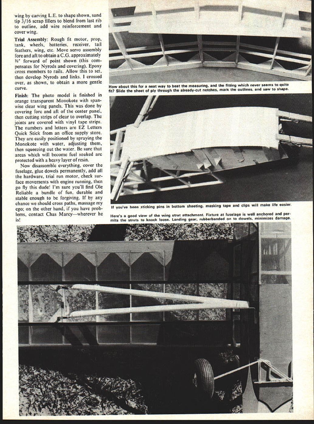
Wing: I am in a wing construction rut. The super-simple technique produces the best strength-weight ratio. Make a master rib of 3/32 or 1/8 ply, cut a stack of rib blanks from 3/32 balsa, pin together, and cut out on a jigsaw. The wing is built flat, needing no shims. The tips are laid flat with bottom spars notched into them. The steps:
- Notch T.E. stock and pin in place.
- Cut tips and pin in place.
- Locate spars with a couple of trial ribs.
- Glue ribs into T.E. notches and over spars.
- Notch L.E. stock and glue onto ribs.
- Add top spars.
- Angle the ribs (2) at center section, using dihedral gauge.
- Add T.E. gussets if you plan to use heat-shrink film for covering.
- Block up wing tip to selected dihedral; use table edge to sand in angle.
- Assemble panel to center section using regular epoxy.
- Repeat for opposite wing.
- Use two hacksaw blades to cut slot through ribs and flush with spars.
- Place ply sheet through slots and mark top and bottom, then remove and saw to shape.
- Epoxy ply gussets liberally, holding against spars with clothespins.
- Repeat for other gusset.
The reason for custom fabricating the ply gussets is to provide for some choice of dihedral and the fact that pre-cut ones never seem to fit anyway. Complete the wing by carving L.E. to shape shown, sand tip 3/16 scrap fillers to blend from last rib to outline, add wire reinforcement and cover wing.
Trial Assembly:
Rough fit motor, prop, tank, wheels, batteries, receiver, tail feathers, wing, etc. Move servo assembly fore and aft to obtain a C.G. approximately 3/8" forward of point shown (this compensates for Nyrods and covering). Epoxy cross members to rails. Allow this to set, then develop Nyrods and links. I crossed over, as shown, to obtain a more gentle curve.
Finish:
The photo model is finished in orange transparent Monokote with span-wise clear wing panels. This was done by covering fore and aft of the center panel, then cutting strips of clear to overlap. The joints are covered with vinyl tape strips. The numbers and letters are EZ Letters Quick Stick from an office supply store. They are easily positioned by spraying the Monokote with water, adjusting them, then squeezing out the water. Be sure that areas which will become fuel soaked are protected with a heavy layer of resin.
Now disassemble everything, cover the fuselage, glue dowels permanently, add all the hardware, trial run motor, check surface movements with engine running, then go fly this dude! I'm sure you'll find Ole Reliable a bundle of fun, durable and stable enough to be forgiving. If by any chance we should cross paths, massage my ego; on the other hand, if you have problems, contact Chas Marcy—wherever he is!
Transcribed from original scans by AI. Minor OCR errors may remain.

