
Ones
Onestep (L. F. Randolph)
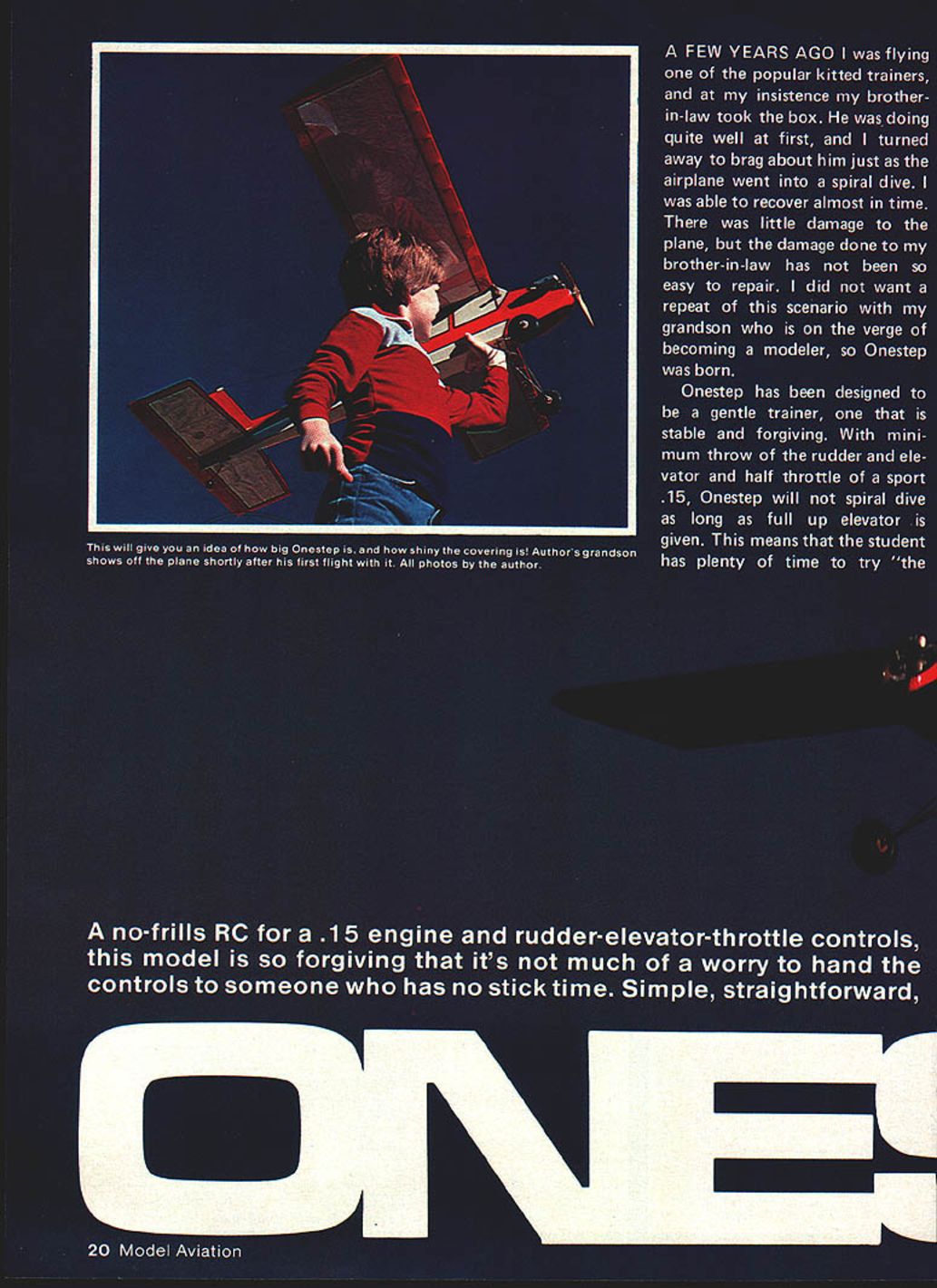
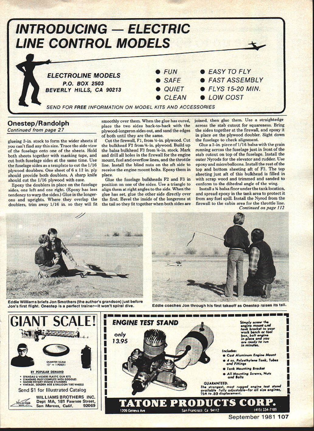
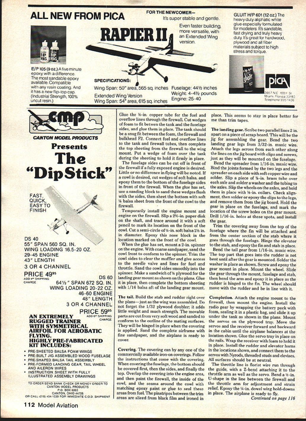
A few years ago I was flying one of the popular kitted trainers, and at my insistence my brother-in-law took the box. He was doing quite well at first, and I turned away to brag about him just as the airplane went into a spiral dive. I was able to recover almost in time. There was little damage to the plane, but the damage done to my brother-in-law has not been so easy to repair. I did not want a repeat of this scenario with my grandson, who is on the verge of becoming a modeler, so Onestep was born.
Onestep has been designed to be a gentle trainer — stable and forgiving. With minimum throw of the rudder and elevator and half throttle on a sport .15, Onestep will not spiral-dive as long as full up elevator is given. This means the student has plenty of time to try the controls. Simple, straightforward, and rugged, Onestep is great for cruising around on a lazy afternoon, for fun-fly competitions, or as a first go at scratch-building — one's first step.
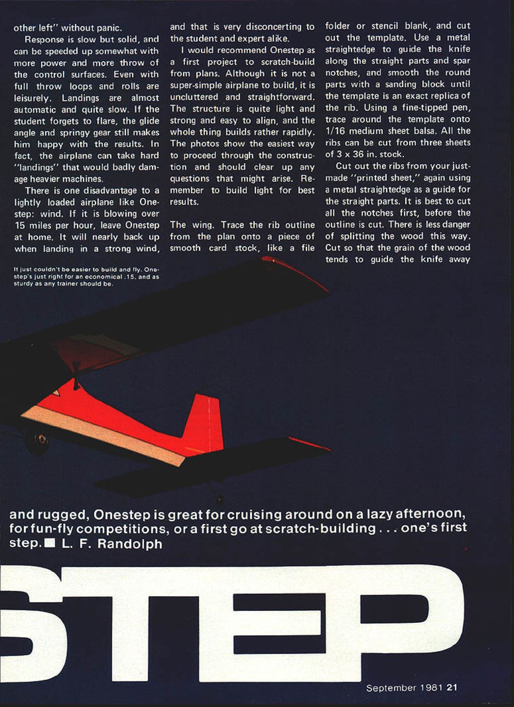
A no-frills RC for a .15 engine with rudder-elevator-throttle controls, this model is so forgiving that it's not much of a worry to hand the controls to someone who has no stick time. Response is slow but solid and can be speeded up somewhat with more power and more throw of the control surfaces. Even with full throw, loops and rolls are leisurely. Landings are almost automatic and quite slow. If the student forgets to flare, the glide angle and springy gear still make for acceptable results. In fact, the airplane can take hard "landings" that would badly damage heavier machines.
There is one disadvantage to a lightly loaded airplane like Onestep: wind. If it is blowing over 15 miles per hour, leave Onestep at home. It will nearly back up when landing in a strong wind, and that is very disconcerting to the student and expert alike.
I recommend Onestep as a first project to scratch-build from plans. Although it is not a super-simple airplane to build, it is uncluttered and straightforward. The structure is quite light and strong and easy to align, and the whole thing builds rather rapidly. The photos (on the original plans) show the easiest way to proceed through construction and should clear up any questions that might arise. Remember to build light for best results.
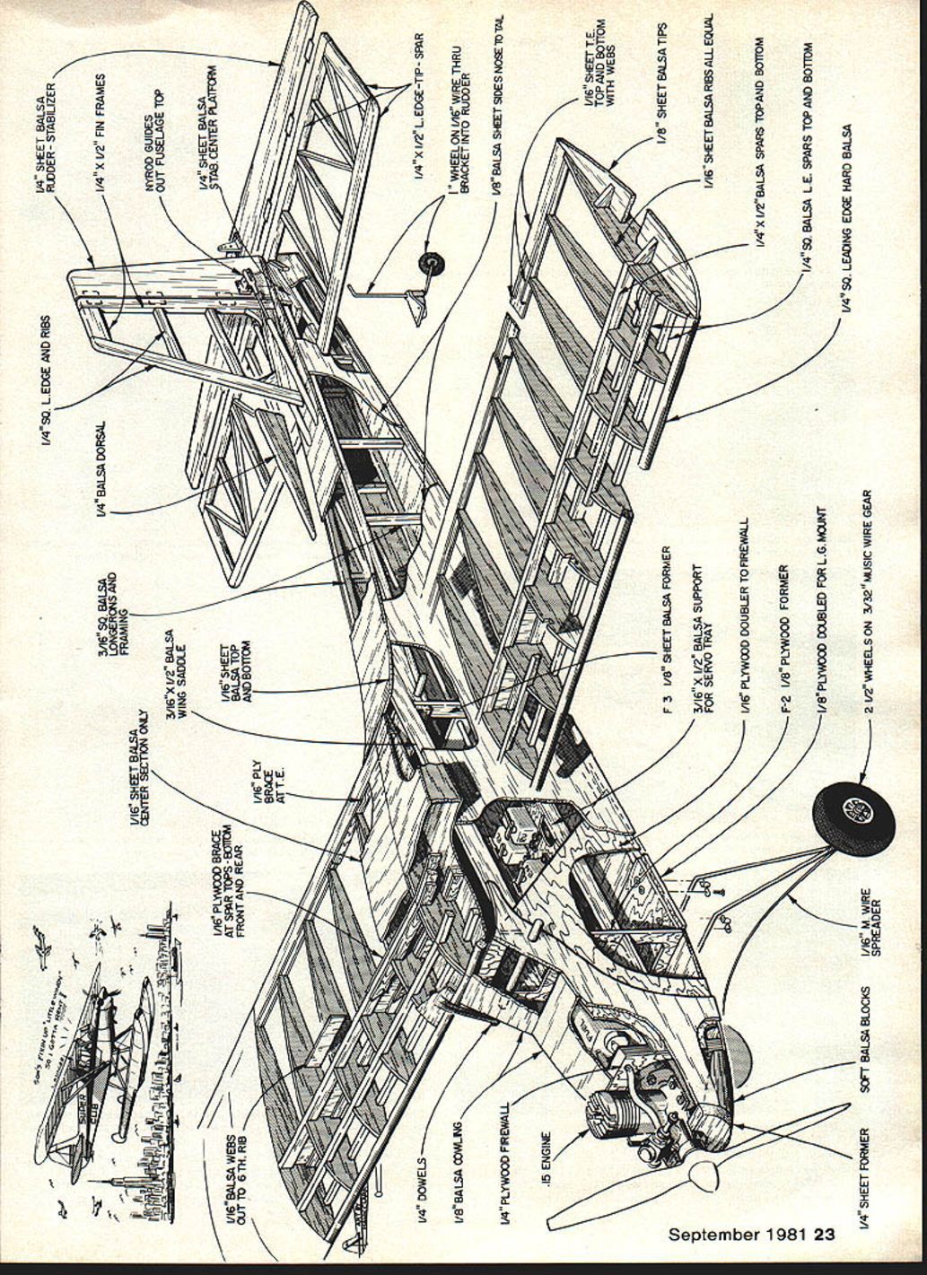
Materials and drawing notes
- 1/16" sheet balsa rudder and stabilizer
- 1/4" x 1/2" fin frames
- 1/4" sq. balsa dorsal
- 1/4" sq. leading edge and ribs
- 1/8" sheet balsa ribs (all equal)
- 1/16" sheet balsa top and bottom (with webs)
- 1/16" sheet balsa tips
- 1/16" sheet balsa center section platform
- 1/16" balsa webs out to 6th rib
- 1/16" plywood brace at spar — tops and bottoms, front and rear
- 3/16" x 3/8" balsa longerons and framing
- 3/16" x 1/2" balsa wing saddle
- 1/4" balsa dorsal
- 1/8" ply brace at stab and rear
- 1/8" plywood formers (soft balsa blocks)
- 1/8" plywood firewall (and plywood doubler to firewall)
- 1/8" plywood doubler for landing-gear mount
- 1/8" ply former for servo tray support (3/16" x 1/2" balsa support for servo tray)
- 1/4" dowels
- 1/8" balsa cowling
- .15 engine (engine shown)
- 1/4" sheet former
- 1/8" sheet balsa former
- 1/16" sheet balsa ribs (all equal)
- 1/4" x 1/2" balsa spars top and bottom
- 1/4" sq. balsa leading-edge spars top and bottom
- 1/4" sq. leading edge (hard balsa)
- 2-1/2" wheels on 3/32" music wire gear
- 1/16" wire spreader
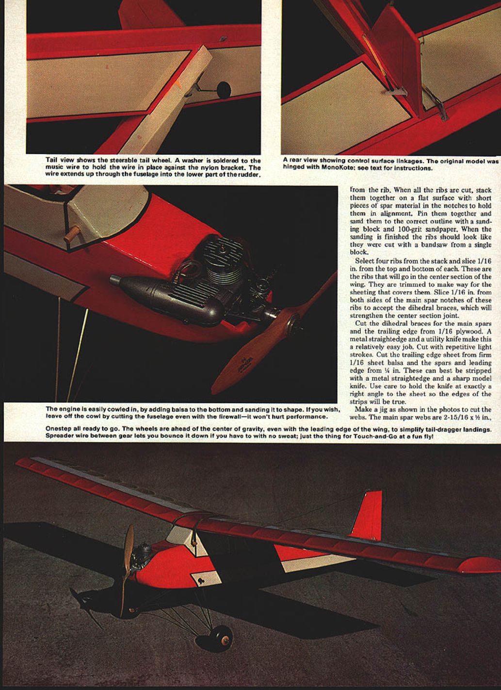
- Wheel on 1/16" wire through bracket into rudder (wire extends up through fuselage lower part to rudder)
- 1/8" music-wire spreader
- Soft balsa blocks (nose)
- 1/8" sheet former
- Nyrod guides
- Tab center plate
- 1/8" sheet balsa lateral details
Note: main spar webs are 2-15/16" x 1/2"; trailing edge webs are 2-15/16" x 1/4". Grain should be vertical to the longest dimension.
Building
General notes
- Make a jig as shown on the plans to cut the spar webs.
- A flat building board is an absolute necessity: about 36" long and at least 12" wide, of a material that will hold pins firmly (3/8" plywood works well).
- Protect plans from glue by covering them with clear plastic wrap or wax paper.
The wing
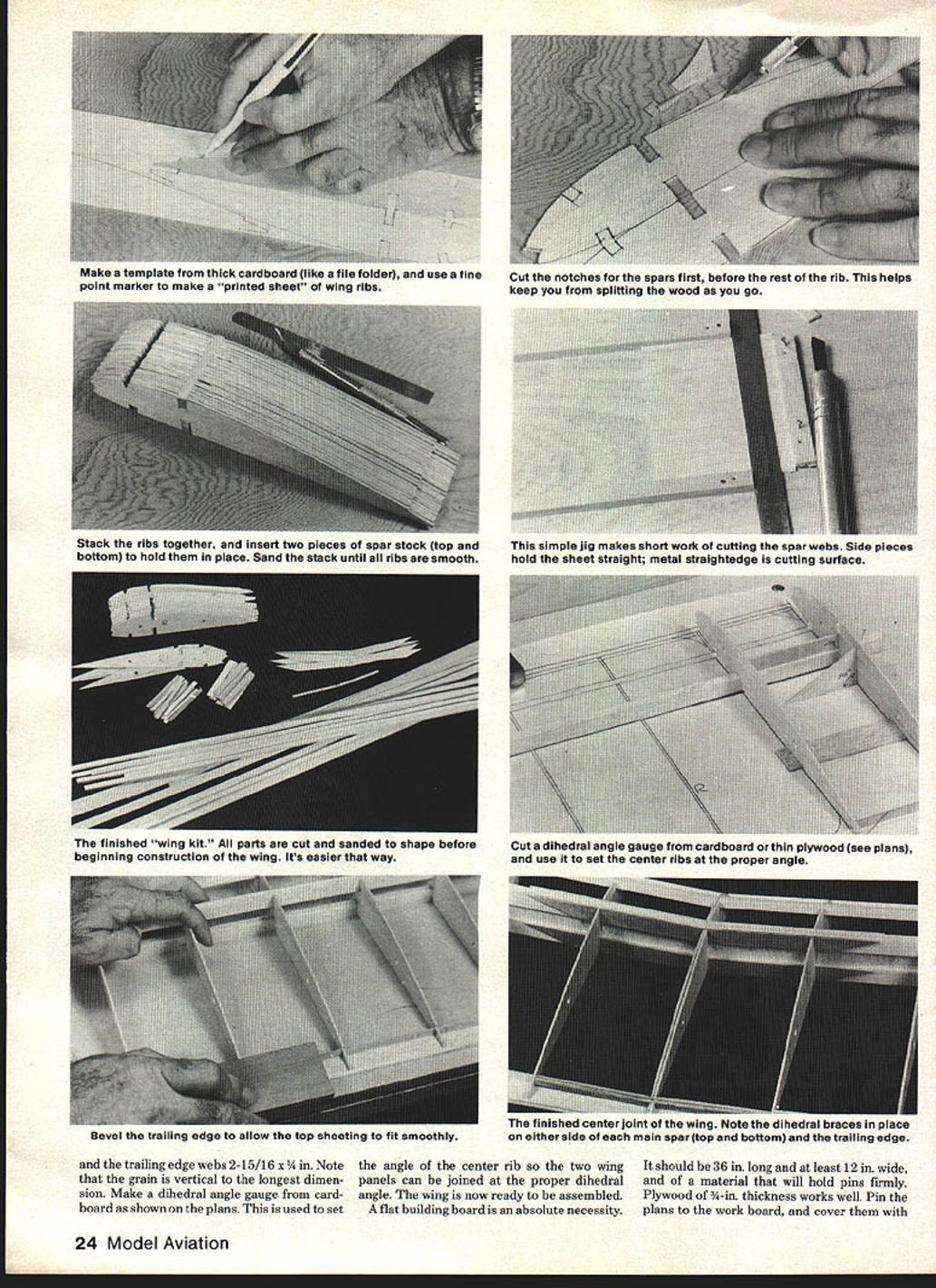
- Make a rib template:
- Trace the rib outline from the plan onto smooth card stock and cut out the template.
- Use a metal straightedge for straight parts and spar notches; smooth round parts with a sanding block until the template exactly matches the plan.
- Trace and cut ribs:
- Use a fine-tipped pen to trace around the template onto 1/16" medium sheet balsa.
- All ribs can be cut from three sheets of 3" x 36" stock.
- Cut all notches first to reduce splitting; guide the knife so the wood grain leads away from the outline.
- Prepare ribs:
- Stack ribs together with short spar pieces in notches to hold alignment. Pin and sand to correct outline with a 100-grit sanding block so they resemble being cut from a single block.
- Select four center ribs and slice 1/16" off the top and bottom of each to accept the center sheeting. Also slice 1/16" from both sides of the main spar notches of these ribs to accept the dihedral braces.
- Cut spars, braces, and trailing edge:
- Cut dihedral braces for the main spars and the trailing edge from 1/16" plywood (use light repetitive strokes).
- Cut trailing edge sheet from firm 1/16" balsa.
- Strip spars and leading edge from 1/4" stock using a metal straightedge and sharp knife; keep knife at right angle so edges remain true.
- Make the main spar webs 2-15/16" x 1/2" and the trailing edge webs 2-15/16" x 1/4".
- Assemble wing halves:
- Pin the bottom trailing edge sheeting and bottom main spar over the plan. Use a 1/16" scrap as a shim under the two center ribs to provide room for center sheeting.
- Using a cardboard dihedral gauge made from the plans, trim the ends of two main spar webs and two trailing edge webs to the dihedral angle.
- Temporarily place scrap 1/16" balsa on both sides of the main spar at center to substitute for dihedral braces and set the center rib at the proper angle. Glue the center rib only to the top of the spar and the bottom trailing edge sheeting.
- Glue one trimmed spar web and one trailing edge web next to the center rib. Continue adding the next center rib, gluing to top of main spar, webs, and trailing edge sheeting.
- Install webs and the first regular rib, then continue adding ribs and webs out to the tip. Note: spar webs do not extend all the way out; trailing edge webs do.
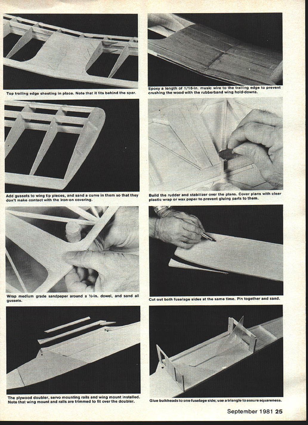
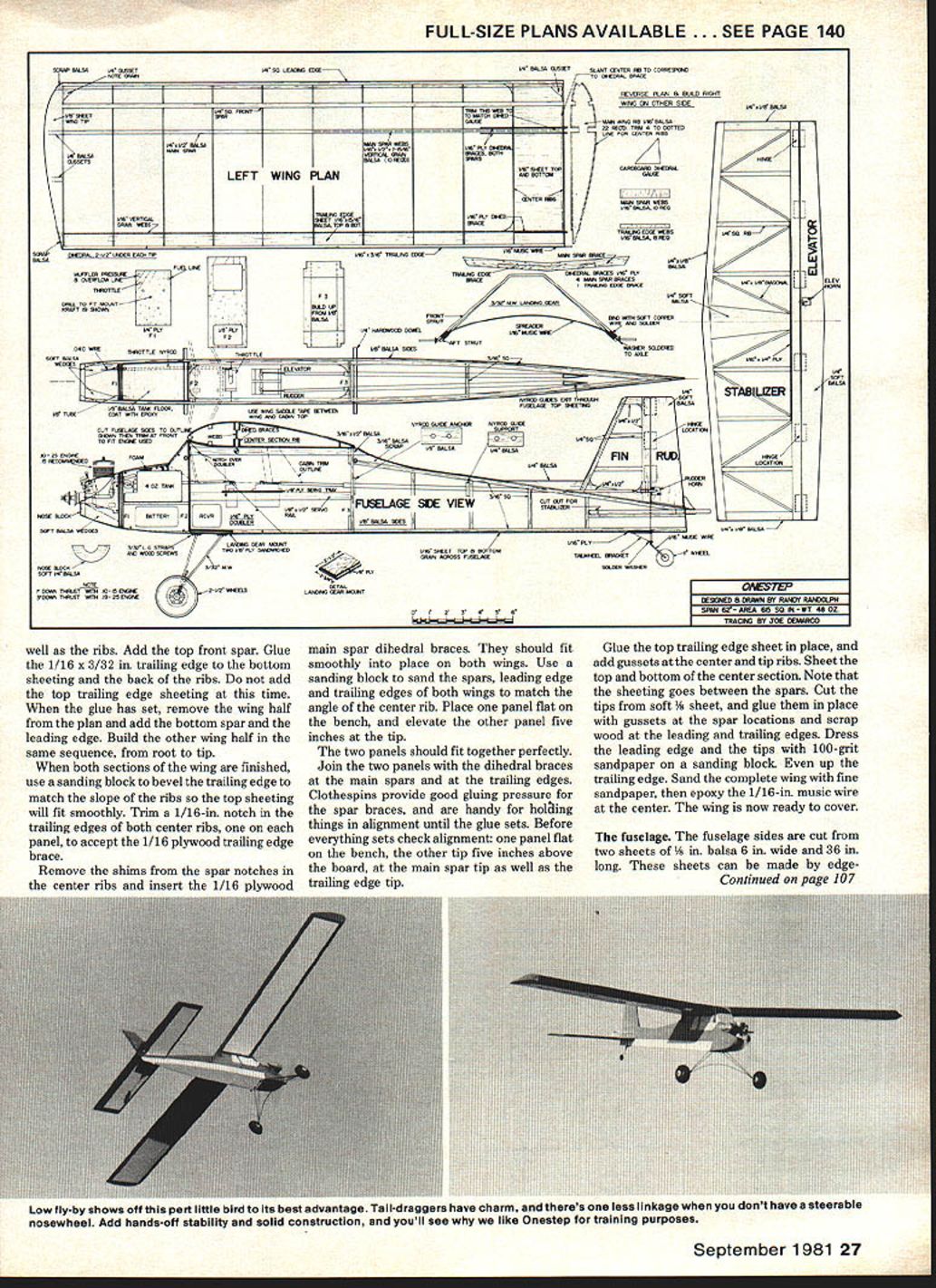
- After all ribs are glued, add the top main spar (glue it to the webs) and apply the top trailing edge sheeting (fits behind the spar). Pin and glue in place.
- Trim spar and trailing edge webs flush, install last two tip ribs and tip pieces, and sand tips so covering will not contact them.
- Finish panels and join:
- Add the top front spar and glue a 1/16" x 3/32" trailing edge to bottom sheeting and back of ribs; do not add top trailing edge sheeting yet.
- Remove wing half from plan, add bottom spar and leading edge. Build the other half in the same sequence.
- Bevel the trailing edge with a sanding block to match rib slope so top sheeting fits smoothly. Trim a 1/16" notch in the center ribs' trailing edges to accept the 1/16" plywood trailing edge brace.
- Remove shims and insert the 1/16" plywood main spar dihedral braces so they fit on both wings. Sand spars, leading and trailing edges to match center rib angle.
- Place one panel flat, elevate the other panel 5" at the tip, fit together using the dihedral braces at main spars and trailing edges. Use clothespins for gluing pressure and alignment.
- Glue top trailing edge sheeting in place, add gussets at center and tip ribs, and sheet the top and bottom of the center section (sheeting goes between the spars).
- Cut tips from soft 1/8" sheet and glue with gussets at spar locations and scrap wood at leading and trailing edges. Dress and sand leading edge and tips with 100-grit, then fine sand the complete wing.
- Epoxy a length of 1/16" music wire at the center to prevent crushing by rubber-band wing hold-downs. The wing is now ready to cover.
The fuselage
- Cut fuselage sides:
- Fuselage sides are cut from two sheets of 1/8" balsa, 6" wide and 36" long. If not available, edge-glue 3" stock to form wider sheets.
- Trace the side view, hold both sheets together with masking tape, and cut both sides simultaneously.
- Prepare and attach doublers and framing:
- Use fuselage sides as a template to cut 1/16" plywood doublers (one sheet 6" x 12" should suffice).
- Epoxy the doublers to the fuselage sides. Epoxy is preferred because it warps less.
- Glue in longerons and uprights. Where these overlap doublers, trim away 1/16" so they fit smoothly over them.
- When cured, place sides back-to-back with plywood-longeron sides out and sand edges until both match.
- Firewall and bulkheads:
- Cut firewall F1 from 1/4" plywood; cut bulkhead F2 from 1/8" plywood; build up balsa bulkhead F3 from 1/8" stock.
- Mark and drill holes in the firewall for engine mount, fuel and overflow lines, and the throttle line. Install blind nuts on the aft side for the engine mount bolts and epoxy them in place.
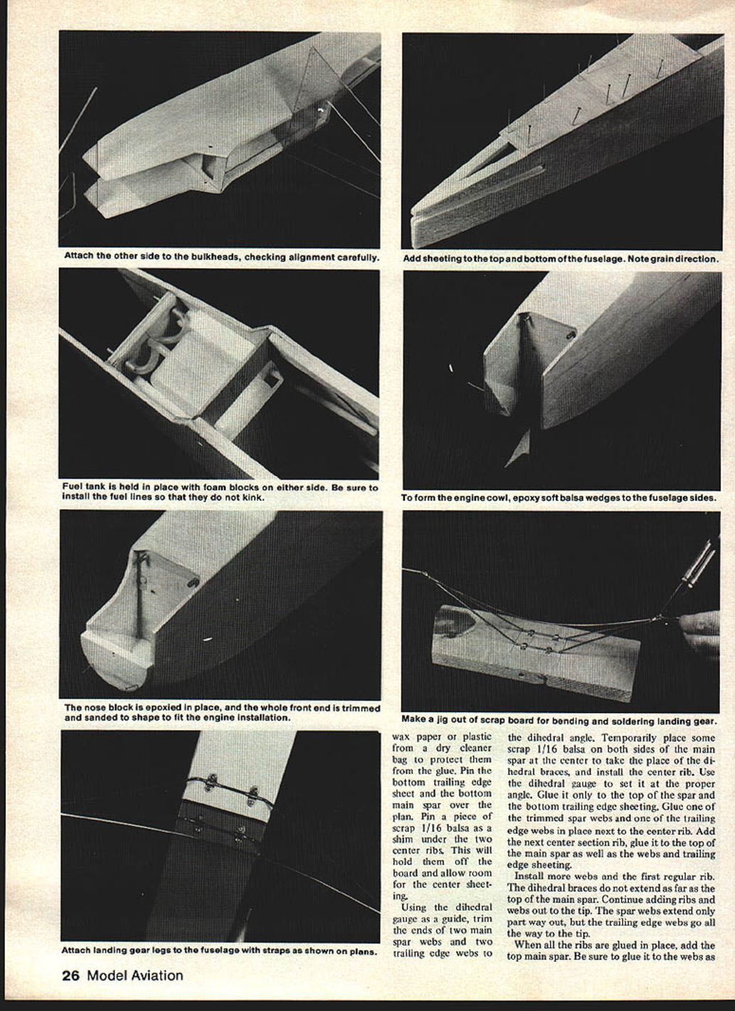
- Glue bulkheads F2 and F3 to one fuselage side, using a triangle to assure they are square to the side. After glue sets, glue the other side directly over the first.
- Join sides and finish fuselage structure:
- Bevel the inside of the longerons at the tail so the sides fit together and glue them. Use a straightedge across the stab cutout to check squareness.
- Bring sides together at the firewall and epoxy it in place on the plywood doubler. Sight down the fuselage to check alignment.
- Glue a 3/8" piece of 1/16" balsa with the grain running across the fuselage just in front of the stab cutout on top of the fuselage. Install outer nyrods for elevator and rudder with epoxy and microballoons.
- Install top and bottom sheeting aft of F3. Fill the top sheeting just aft of this bulkhead with scrap wood and trim/sand to conform to the wing's dihedral angle.
- Tank, throttle and firewall plumbing:
- Install a 3/8" balsa floor under the tank location and spread epoxy in the tank area for fuel protection.
- Glue the 5/16" copper tube for fuel and overflow lines through the firewall.
- Cut foam wedges to fit between the tank and fuselage sides; glue them in place so the tank is snug between the foam, firewall, and bulkhead F2. Connect the fuel and overflow lines to the tank and firewall tubes.
- Install the nyrod from the firewall to the cabin area for the throttle line.
- Cowl and nose block:
- Fuselage sides can be cut off in front of the firewall for a fully exposed engine if desired.
- For a cowl, cut wedges of soft balsa and epoxy them to the bottom of the fuselage sides in front of the firewall. When set, sand flush and sheet the bottom with soft 1/16" balsa from the front of the cowl to the firewall.
- Temporarily install engine mount and engine. Slip a 2-1/2" paper disk on the shaft and trace to mark spinner location on the cowl front.
- Cut a semi-circle nose block from 3/4"-thick soft balsa (2-3/8" diameter) and epoxy in place where marked.
- When set, mount a 2" spinner on the engine, sand cowl front to conform to spinner, trim sides to clear muffler and allow access to needle valve and lines. Sand cowl sides smoothly into the spinner.
- Landing-gear mount and bottom sheeting:
- Make a sandwich of 3/8" plywood for the landing gear mount as shown on the plans and glue it in place.
- Complete bottom sheeting with 1/16" balsa aft of the landing gear mount.
The tail
- Build the stabilizer and rudder directly over the plans exactly as the wing was assembled.
- Do not forget the 1/32" plywood doubler; it adds little weight and much strength.
- Movable parts are cut from very soft wood and sanded to conform to the mating surfaces. Hinges are installed after covering.
- Sand the complete airframe with fine sandpaper; the airplane is then ready to cover.
Covering
- Use any commercially available iron-on covering; follow the manufacturer's instructions.
- When covering the fuselage, cover the bottom first, then the sides, and finally the top.
- Overlap covering into the engine area, then paint the firewall, inside of the cowl, and seams around the cowl with matching epoxy paint or glue to seal them from fuel.
- Pinstripes between trim areas may be sliced from black film and ironed in place; they tend to stay better than trim tape.
The landing gear
- Make a jig by scribing two parallel lines 2" apart on a scrap board. This will hold the gear legs while assembling.
- Bend the two landing gear legs from 3/32" music wire and attach them across the lines on the jig as they will be mounted on the fuselage.
- Bend the spreader from 1/16" music wire. Bind the joints formed by the two legs and the spreader with soft copper wire and solder.
- Slip a piece of 3/16" brass tube over each axle and solder a washer and the tubing to the axles. Slip the wheels on the axles and hold them with 1/16" collars.
- Check alignment, then solder or epoxy the clips to the legs and remove them from the jig.
- Hold the gear in place on the fuselage, mark screw hole locations on the gear mount, drill 1/16" holes, and install the gear.
Completion
- Attach the engine mount to the firewall and mount the engine.
- Install radio gear: wrap the battery pack with foam, seal it in a plastic bag, and slide it under the tank as shown on the plans.
- Mount servos on the plywood tray. Move servos and receiver forward and backward in the cabin until the airplane balances at the location shown on the plans. Glue the servo tray to the rails and wrap the receiver with foam to hold it.
- Install rudder and elevator horns and connect to servos with nyrods, threaded studs, and clevises. Set all surfaces to neutral.
- The throttle line is florist wire run through the guide, with a Z-bend attaching it to the throttle arm and the servo. Bend a 1/4" U-shape in the line between the firewall and throttle arm for adjustment and strain relief.
- Epoxy 1/8" dowel wing hold-downs in place. The airplane is now ready to fly.
Flying
- As with all new installations, range-check the radio and check movement and direction of surfaces with the engine running.
- Onestep handles very well on the ground. Tracking on takeoff is excellent into the wind; lift-off is rather rapid because of the light wing loading — be ready for it.
- With a .15 at full throttle, climb-out is about a 45° angle. Half throttle provides the best cruise.
- If the outermost holes in the rudder and elevator horns are used, control response is quite gentle. The classic vertical spiral dive must be done deliberately by holding down elevator.
- Landings are quite slow with the application of back stick. Onestep can be bounced in for precision landings and will withstand firm touchdowns.
- By increasing the throw of the control surfaces, rolls and snaps are possible. Inverted flight is possible but requires lots of forward stick.
- As well as being a solid, stable trainer, Onestep will hold its own in fun-flys. It will loop tightly and can carry more than its own weight of payload if needed.
This model is a good first step.
■ L. F. Randolph
Transcribed from original scans by AI. Minor OCR errors may remain.

