
Onestone
L. F. Randolph
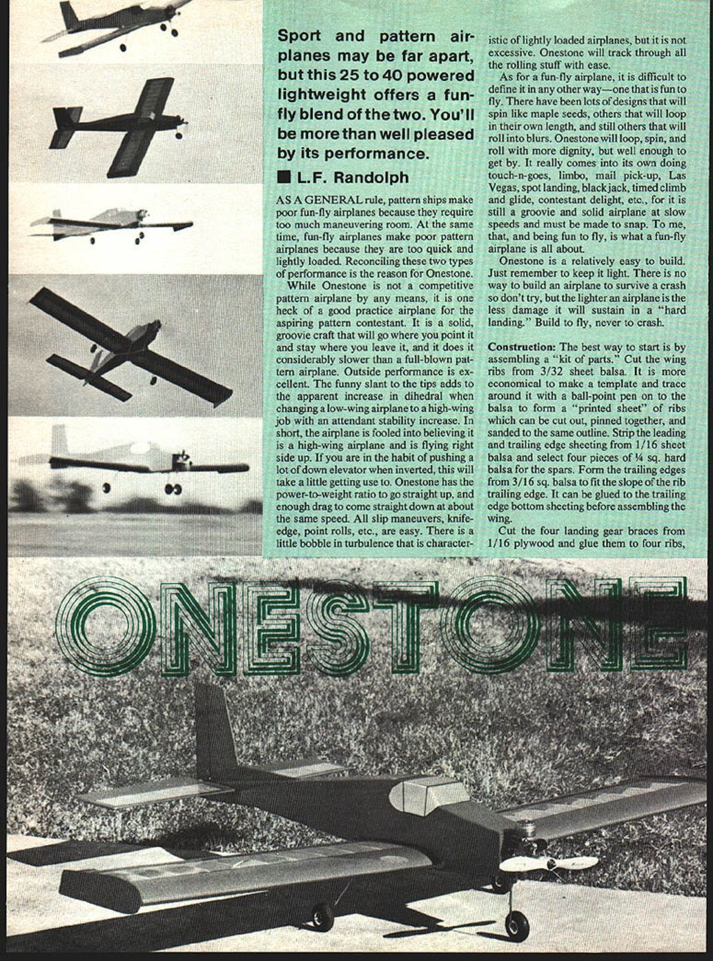
As a general rule, pattern ships make poor fun-fly airplanes because they require too much maneuvering room. At the same time, fun-fly airplanes make poor pattern airplanes because they are too quick and lightly loaded. Reconciling these two types of performance is the reason for Onestone.
While Onestone is not a competitive pattern airplane by any means, it is one heck of a good practice airplane for the aspiring pattern contestant. It is a solid, groovy craft that will go where you point it and stay where you leave it, and it does it considerably slower than a full-blown pattern airplane. Outside performance is excellent. The funny slant to the tips adds to the apparent increase in dihedral when changing a low-wing airplane to a high-wing job with an attendant stability increase. In short, the airplane is fooled into believing it is a high-wing airplane and is flying right side up. If you are in the habit of pushing a lot of down elevator when inverted, this will take a little getting used to. Onestone has the power-to-weight ratio to go straight up, and enough drag to come straight down at about the same speed. All slip maneuvers, knife-edge, point rolls, etc., are easy. There is a little bobble in turbulence that is characteristic of lightly loaded airplanes, but it is not excessive. Onestone will track through all the rolling stuff with ease.
As for a fun-fly airplane, it is difficult to define it in any other way — one that is fun to fly. There have been lots of designs that will spin like maple seeds, others that will loop in their own length, and still others that will roll into blurs. Onestone will loop, spin, and roll with more dignity, but well enough to get by. It really comes into its own doing touch-n-goes, limbo, mail pick-up, Las Vegas, spot landing, blackjack, timed climb and glide, contestant delight, etc., for it is still a groovy and solid airplane at slow speeds and must be made to snap. To me, that, and being fun to fly, is what a fun-fly airplane is all about.
Onestone is relatively easy to build. Just remember to keep it light. There is no way to build an airplane to survive a crash so don't try, but the lighter an airplane is the less damage it will sustain in a "hard landing." Build to fly, never to crash.
Construction
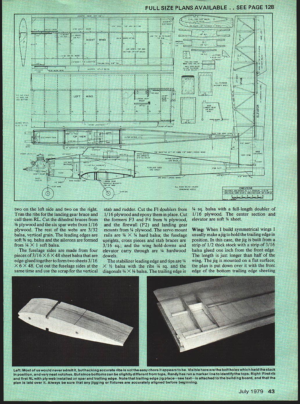
The best way to start is by assembling a "kit of parts." Cut the wing ribs from 3/32" sheet balsa. It is more economical to make a template and trace around it with a ball-point pen onto the balsa to form a "printed sheet" of ribs which can be cut out, pinned together, and sanded to the same outline. Strip the leading and trailing edge sheeting from 1/16" sheet balsa and select four pieces of 1/4" sq. hard balsa for the spars. Form the trailing edges from 3/16" sq. balsa to fit the slope of the rib trailing edge. It can be glued to the trailing edge bottom sheeting before assembling the wing.
Cut the four landing gear braces from 1/16" plywood and glue them to four ribs, two on the left side and two on the right. Trim the ribs for the landing gear brace and call them RL. Cut the dihedral braces from 1/8" plywood and the six spar webs from 1/16" plywood. The rest of the webs are 3/32" balsa, vertical grain. The leading edges are soft 3/8" sq. balsa and the ailerons are formed from 1/4" x 1" soft balsa.
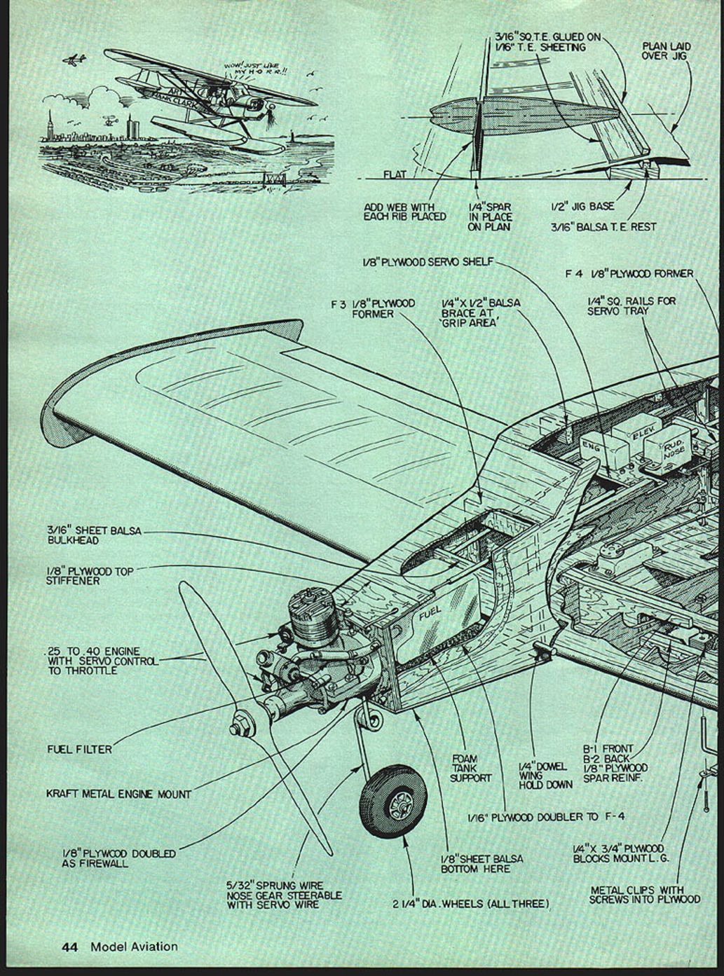
The fuselage sides are made from four pieces of 3/16" x 6" x 48" sheet balsa that are edge-glued together to form two sheets 3/16" x 6" x 48". Cut out the fuselage sides at the same time and use the scrap for the vertical stab and rudder. Cut the F1 doublers from 1/16" plywood and epoxy them in place. Cut the formers F3 and F4 from 1/8" plywood, and the firewall (F2) and landing gear mounts from 1/4" plywood. The servo mount rails are 1/8" x 1/4" hard balsa; the fuselage uprights, cross pieces and stab braces are 3/16" sq.; and the wing hold-downs and elevator carry-through are 1/4" hardwood dowels.
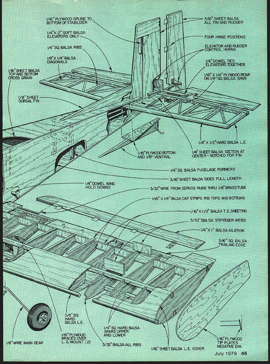
The stabilizer leading edge and tips are 1/4" x 1/4" balsa with the ribs 1/4" sq. and the diagonals 1/4" x 1/8" balsa. The trailing edge is 1/4" sq. balsa with a full-length doubler of 1/16" plywood. The center section and elevator are soft 1/4" sheet.
Materials and details (notes)
- Ribs: 3/32" balsa
- Leading edge cover: 1/16" sheet balsa
- Spars: 1/4" sq. hard balsa (upper and lower)
- Trailing edge: 3/16" sq. balsa with 1/16" T.E. sheeting
- Trailing edge cap strips: 1/16" x 1/4" balsa
- Trailing edge stiffener webs: 3/32" balsa
- Aileron: 1/4" x 1" soft balsa
- Aileron hardware: torque rod installation at trailing edge
- Dihedral braces: 1/8" plywood
- Spar webs: six of 1/16" plywood, others 3/32" balsa
- Leading edges: 3/8" sq. hard balsa
- Main gear: 1/8" wire; nose gear: 5/32" sprung wire steerable with servo
- Wheels: 2 1/4" diameter (all three)
- Engine: .25 to .40 with servo control to throttle
- Firewall: 1/8" plywood doubled; also a 1/8" ply top stiffener and 1/8" plywood doubled as firewall noted elsewhere
- Engine mount: kraft metal engine mount with 1/4" x 3/4" plywood blocks to mount landing gear
- Landing gear braces: 1/16" plywood (two per side)
- Fuselage formers: 1/4" sq. balsa and 1/8" plywood where noted
- Fuselage sides: 3/16" sheet balsa full length
- Stabilizer: 1/4" sq. ribs, 1/8" x 1/4" diagonals, 1/16" plywood doubler, 1/16" sheet top and bottom cross grain
- Elevator: 1/4" sheet with 1/4" hardwood dowel in leading edge; elevators tied together with 1/4" dowel
- Rudder and fin: 3/16" sheet balsa; dorsal fin 1/8" sheet
- Tip plates: 1/16" plywood tip plates for negative dihedral
- Reinforcements: 1/16" x 1/4" plywood reinforcements on 1/4" sq. spar; 1/16" plywood bottom and 1/8" ventral
- Servo wiring: 3/32" balsa stiffener; 3/32" wire from servos runs through 1/8" brass tube
- Wing hold-downs: 1/4" dowel
- Misc: foam tank support, fuel filter, metal clips with screws into plywood for mounting, plywood spar reinforcements
(Always be sure that any jigging or fixtures are accurately aligned before beginning.)
Wing
When I build symmetrical wings I usually make a jig to hold the trailing edge in position. In this case, the jig is built from a strip of 1/2" thick stock with a strip of 3/16" balsa glued one inch from the front edge. The length is just longer than half of the wing. The jig is mounted on a flat surface; the plan is put down over it with the front edge of the bottom trailing edge sheeting aligned with the front edge of the jig. Cover the plan with plastic sheet and pin the bottom spar and trailing edge sheeting in place, and assemble the wing just as if it had a flat bottom.
It is best to start assembly with the first rib outboard of the dihedral joint. Add the plywood webs, the first RL, plywood webs, the next RL, balsa webs, the next rib, and so on to the tip. The tip rib is glued at an angle. Cut the template from the plans and use it to set this rib and its opposite number at the proper angle. Next, add the 3/8" sq. leading edge and the top main spar and remove the assembled wing half from the board. The other half is built in the same order. Do not add the top leading and trailing edge sheeting until later.
When both halves are complete, bevel the leading edges, spars and trailing edges at the center to fit the dihedral angle, and join them with the dihedral braces. The first rib on each side of the center will require widening of the spar notches to receive the extensions on the dihedral braces. Use a good aliphatic resin glue, and install them with the longest brace, B1, in front of the spar. Install the trailing edge brace and glue the leading edge together. The two remaining ribs are trimmed to fit between the leading edge and the front dihedral brace, glued together, and installed at the center with 3/16" gussets on each side.
From the spar aft, the ribs are trimmed to fit between the rear brace and the trailing edge brace. They are installed to form the servo cut-out aft of the spar. Add the trailing edge webs, and the rest of the sheeting top and bottom, and the cap strips. The aileron hardware is installed at the trailing edge location and faired into the wing with scrap. The ailerons will be installed when the wing is covered.
(Note: For sheet sanding make up a wide sanding board from plywood. Accurate joining of panels is as important as bending a fuselage over the centerline.)
Wing hardware and alignment notes
- Install dihedral braces with the longest brace (B1) in front of the spar.
- Glue dihedral braces with good aliphatic resin glue.
- Install trailing edge webs and cap strips after joining halves.
- Ailerons: groove and drill to receive torque wire; aileron hardware faired into the wing.
Fuselage
Tape or pin the two fuselage sides together and sand them to the same shape, then square the edges. While they are taped together, drill the holes for the wing hold-down dowels. Separate the sides and glue in the servo rails, uprights, and stabilizer braces.
With one side on a flat surface, glue the two fuselage formers into the locations shown on the plans, using a square or right triangle to be sure they are exactly square with the fuselage side. When the glue has set, glue the other fuselage side into position directly over the first, onto the formers; again, use a square to align the sides exactly over each other.
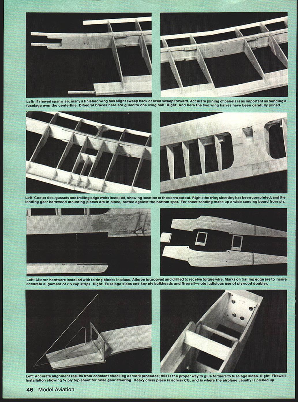
Drill the firewall for the mounting bolts, fuel and throttle lines. Pull the fuselage sides in at the front and install the firewall with epoxy. The tail is then brought together, beveled to form a joint with a total width of 3/16" at the rear, and glued. Install all cross braces and add the bottom sheeting: 1/8" in front of the wing and 1/16" aft. Install the outer nylon rods for the elevator and rudder, the fuel tank and lines, and the inner nylon rod for the throttle.
The tank is braced in position with foam on all sides. Place the 1/8" plywood in position on top of the fuselage at the firewall and mark the location of the nose gear steering linkage exit. Drill and bevel a hole to fit the inner nylon rod at that spot, and glue the plywood into position. Install the inner nylon rod for the nose gear and complete the top sheeting: 1/8" forward of the cabin and 1/16" aft. Mount the sub-rudder at the tail and the fuselage is ready for sanding.
(Accurate alignment results from constant checking as work proceeds; glue formers carefully to fuselage sides. The heavy cross piece across the CG is where the airplane usually is picked up.)
Stabilizer and Elevator
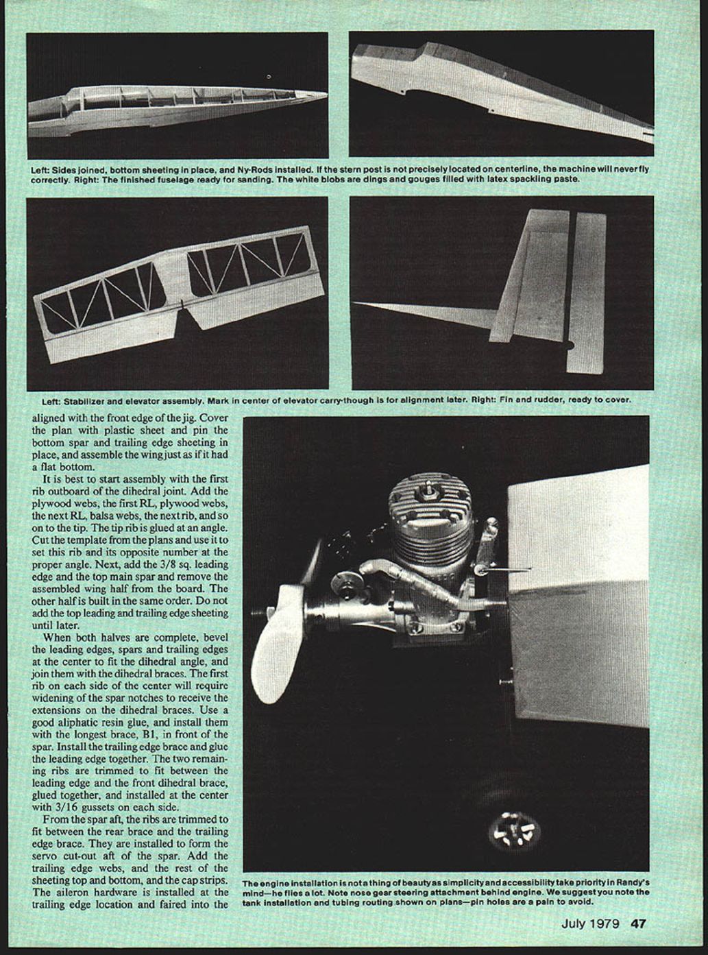
The stabilizer is built over the plan in the conventional manner; do not omit the 1/16" plywood doubler. The elevator is cut from soft 1/4" sheet balsa, and the 1/4" hardwood dowel is installed in the leading edge before the rudder cut-out is made in the trailing edge; this ensures that both sides of the elevator are in line. The vertical stab is made from four pieces of 3/16" scrap from the fuselage sides with an internal 1/16" plywood spar. Join the stab and the elevator, and the fin and rudder, and sand round all edges exposed to airflow.
Covering
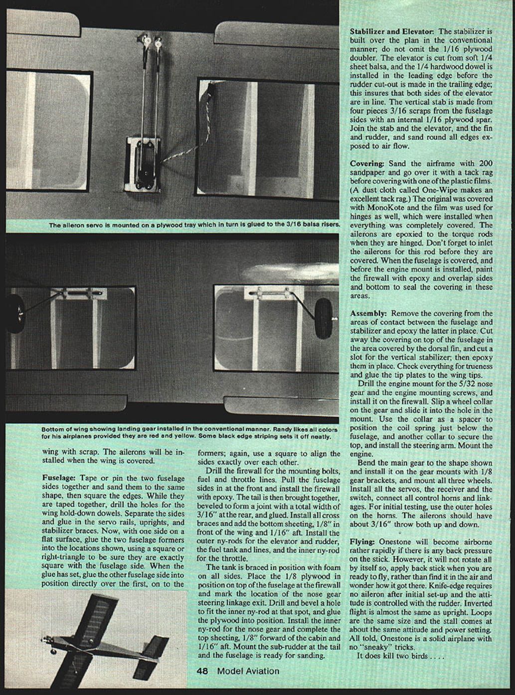
Sand the airframe with 200-grit sandpaper and go over it with a tack rag before covering with one of the plastic films. (A dust cloth called One-Wipe makes an excellent tack rag.) The original was covered with MonoKote and the film was used for hinges as well, which were installed when everything was completely covered. The ailerons are epoxied to the torque rods when they are hinged. Don't forget to inlet the ailerons for this rod before they are covered. When the fuselage is covered, and before the engine mount is installed, paint the firewall with epoxy and overlap sides and bottom to seal the covering in these areas.
Assembly
Remove the covering from the areas of contact between the fuselage and stabilizer and epoxy the latter in place. Cut away the covering on top of the fuselage in the area covered by the dorsal fin, and cut a slot for the vertical stabilizer, then epoxy them in place. Check everything for trueness and glue the tip plates to the wing tips.
Drill the engine mount for the 5/32" nose gear and the engine mounting screws, and install it on the firewall. Slip a wheel collar on the gear and slide it into the hole in the mount. Use the collar as a spacer to position the coil spring just below the fuselage, and another collar to secure the top, and install the steering arm. Mount the engine.
Bend the main gear to the shape shown on the plans and install it on the gear mounts with 1/8" gear brackets, and mount all three wheels. Install all the servos, the receiver and the switch, connect all control horns and linkages. For initial testing, use the outer holes on the horns. The ailerons should have about 3/16" throw both up and down.
Flying
Onestone will become airborne rather rapidly if there is any back pressure on the stick. However, it will not rotate all by itself, so apply back stick when you are ready to fly, rather than find it in the air and wonder how it got there. Knife-edge requires no aileron after initial set-up and the attitude is controlled with the rudder. Inverted flight is almost the same as upright. Loops are the same size and the stall comes at about the same attitude and power setting. All told, Onestone is a solid airplane with no "sneaky" tricks.
It does kill two birds . . .
Transcribed from original scans by AI. Minor OCR errors may remain.

