

Optoglo
Brent Dane
AN ONBOARD GLOW system can add safety and convenience to any model engine. Even in cases for which glow current is not required at idle, an electronic glow system can be connected to an unused radio channel, allowing the glow current to be switched on and off with just the flip of a switch on the transmitter.
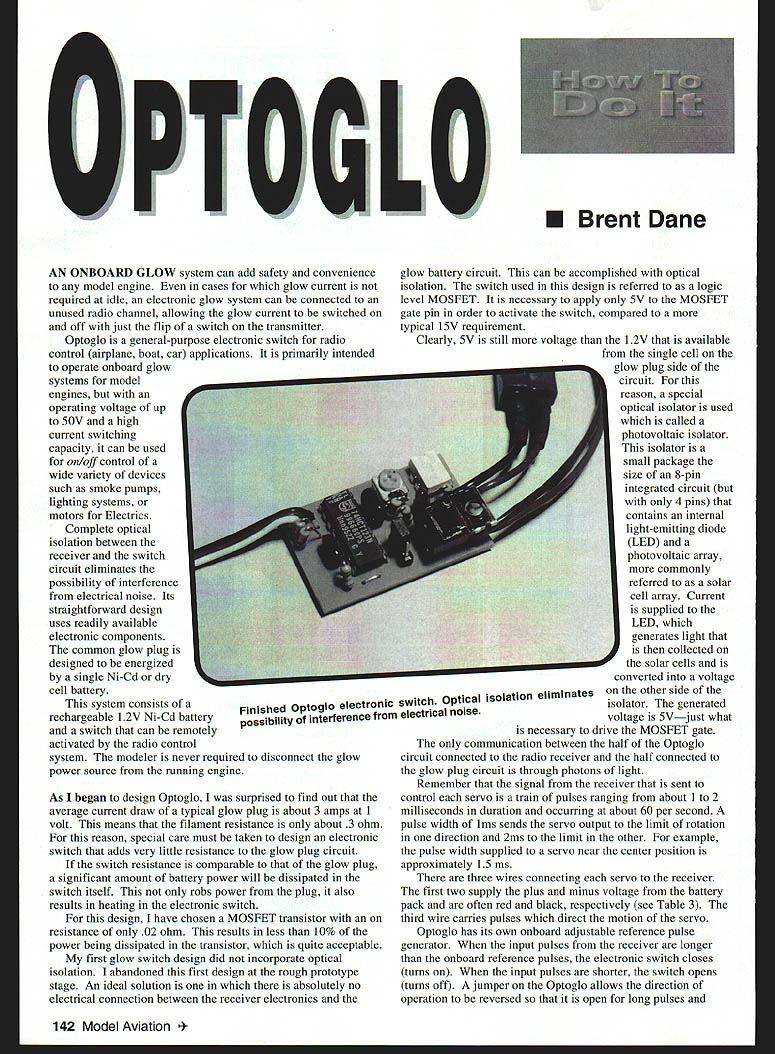
Optoglo is a general-purpose electronic switch for radio-control (airplane, boat, car) applications. It is primarily intended to operate onboard glow systems for model engines, but with an operating voltage of up to 50 V and a high-current switching capacity, it can be used for on/off control of a wide variety of devices such as smoke pumps, lighting systems, or motors for electrics.
Complete optical isolation between the receiver and the switch circuit eliminates the possibility of interference from electrical noise. Its straightforward design uses readily available electronic components.
The common glow plug is designed to be energized by a single Ni-Cd or dry cell battery. This system consists of a rechargeable 1.2 V Ni-Cd battery and a switch that can be remotely activated by the radio-control system. The modeler is never required to disconnect the glow power source from the running engine.
Design considerations
As I began to design Optoglo, I was surprised to find that the average current draw of a typical glow plug is about 3 amps at 1 volt. This means the filament resistance is only about 0.3 ohm. For this reason, special care must be taken to design an electronic switch that adds very little resistance to the glow-plug circuit. If the switch resistance is comparable to that of the glow plug, a significant amount of battery power will be dissipated in the switch itself. This not only robs power from the plug, it also results in heating in the electronic switch.
For this design I have chosen a MOSFET transistor with an on-resistance of only 0.02 ohm. This results in less than 10% of the power being dissipated in the transistor, which is acceptable.
My first glow-switch design did not incorporate optical isolation. I abandoned that first design at the rough-prototype stage. An ideal solution is one in which there is absolutely no electrical connection between the receiver electronics and the glow-battery circuit. This can be accomplished with optical isolation.
The switch used in this design is referred to as a logic-level MOSFET. It is necessary to apply only 5 V to the MOSFET gate pin in order to activate the switch, compared to a more typical 10–15 V requirement. Since 5 V is more than the 1.2 V available from the single cell on the glow-plug side of the circuit, a photovoltaic isolator is used. This isolator is a small package (about the size of an 8-pin integrated circuit but with only 4 pins) that contains an internal light-emitting diode (LED) and a photovoltaic array (solar-cell array). Current is supplied to the LED, which generates light that is collected by the solar cells and converted into a voltage on the other side of the isolator. The generated voltage is about 5 V—just what is necessary to drive the MOSFET gate.
The only communication between the receiver side and the glow-plug side of the Optoglo circuit is through photons of light.
How the radio signal is interpreted
The signal from the receiver that is sent to control each servo is a train of pulses ranging from about 1 to 2 milliseconds in duration and occurring at about 60 per second. A pulse width of 1 ms sends the servo output to the limit of rotation in one direction and 2 ms to the limit in the other. For example, the pulse width supplied to a servo near the center position is approximately 1.5 ms.
There are three wires connecting each servo to the receiver. The first two supply the plus and minus voltage from the battery pack and are often red and black, respectively. The third wire carries pulses which direct the motion of the servo.
Optoglo has its own onboard adjustable reference pulse generator. When the input pulses from the receiver are longer than the onboard reference pulses, the electronic switch closes (turns on). When the input pulses are shorter, the switch opens (turns off). A jumper on the Optoglo allows the direction of operation to be reversed so that it is open for long pulses and closed for short pulses, or closed for long pulses and open for short pulses. Therefore the jumper functions similarly to a servo-reversing switch.
Electronics overview
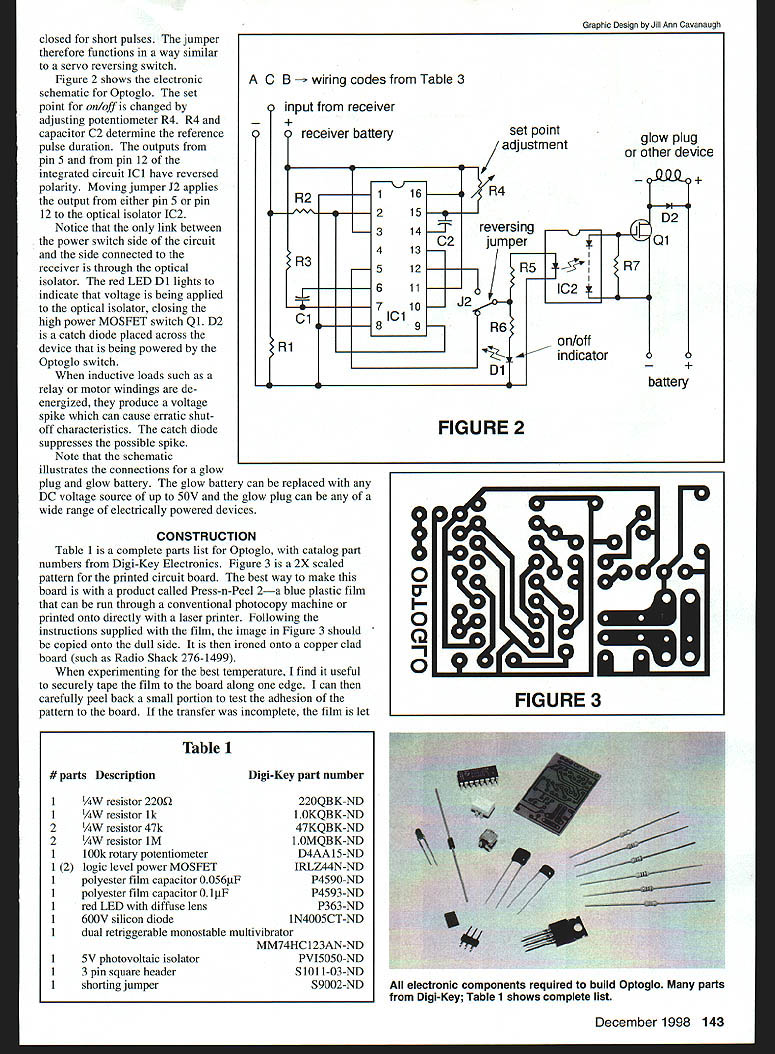
Figure 2 shows the electronic schematic. Optoglo set point on/off is changed by adjusting potentiometer R4. R4 and capacitor C2 determine reference pulse duration. Outputs are pin 5 and pin 12 of the integrated circuit IC1. If the polarity is reversed, moving jumper J2 applies the output to either pin 5 or pin 12. Optical isolator IC2 provides the link between the power-switch side of the circuit and the receiver side through light.
Red LED D1 lights to indicate voltage being applied to the optical isolator and the closing of the high-power MOSFET switch Q1. D2 is a catch diode placed across the device being powered. Optoglo will switch inductive loads such as relays or motor windings; the catch diode protects the MOSFET from de-energized-product voltage spikes.
Note that the schematic illustrates the connections for a glow plug and glow battery. The glow battery can be replaced with any DC voltage source of up to 50 V and the glow plug can be any of a wide range of electrically powered devices.
CONSTRUCTION
Parts list (Table 1)
- 1 — 1/4 W resistor 220 Ω — Digi-Key 220QBK-ND
- 1 — 1/4 W resistor 1 k Ω — Digi-Key 1.0KQBK-ND
- 1 — 1/4 W resistor 47 k Ω — Digi-Key 47KQBK-ND
- 2 — 1/4 W resistor 1 M Ω — Digi-Key 1.0MQBK-ND
- 1 — 100 k rotary potentiometer — Digi-Key D4A1AS-ND
- 1 (or 2) — logic-level power MOSFET — Digi-Key IRLZ44N-ND
- 1 — polyester film capacitor 0.056 µF — Digi-Key P4590-ND
- 1 — polyester film capacitor 0.1 µF — Digi-Key P4593-ND
- 1 — red LED with diffuse lens — Digi-Key P363-ND
- 1 — 600 V silicon diode — Digi-Key 1N4005CT-ND
- 1 — dual retriggerable monostable multivibrator — Digi-Key MM74HC123AN-ND
- 1 — 5 V photovoltaic isolator — Digi-Key PV15050-ND
- 1 — 3-pin square header — Digi-Key S1011-03-ND
- 1 — shorting jumper — Digi-Key S9002-ND
PCB fabrication
Figure 3 is a 2X scaled pattern for the printed circuit board. The best way to make this board is with Press-n-Peel 2 (a blue plastic film that can be run through a conventional photocopy machine or printed directly with a laser printer). Following the film instructions, copy the image in Figure 3 onto the dull side. Iron the image onto a copper-clad board (such as Radio Shack 276-1499).
When experimenting for the best temperature, tape the film to the board along one edge. Carefully peel back a small portion to test the adhesion of the pattern to the board. If the transfer is incomplete, let the film back down and apply additional pressure at a higher temperature.
After successful image transfer, etch the board in a solution of ferric chloride (Radio Shack 276-1535) for 30–60 minutes or until all unwanted copper is gone. This particular blank board is two-sided, so the copper will be completely removed from the back side.
After etching, drill mounting holes with a #65 drill bit. The copper surrounding each hole location accurately guides the drilling. Slightly larger holes will be required for the MOSFET pins and the glow-plug and battery wires. Use the smallest possible holes in each case.
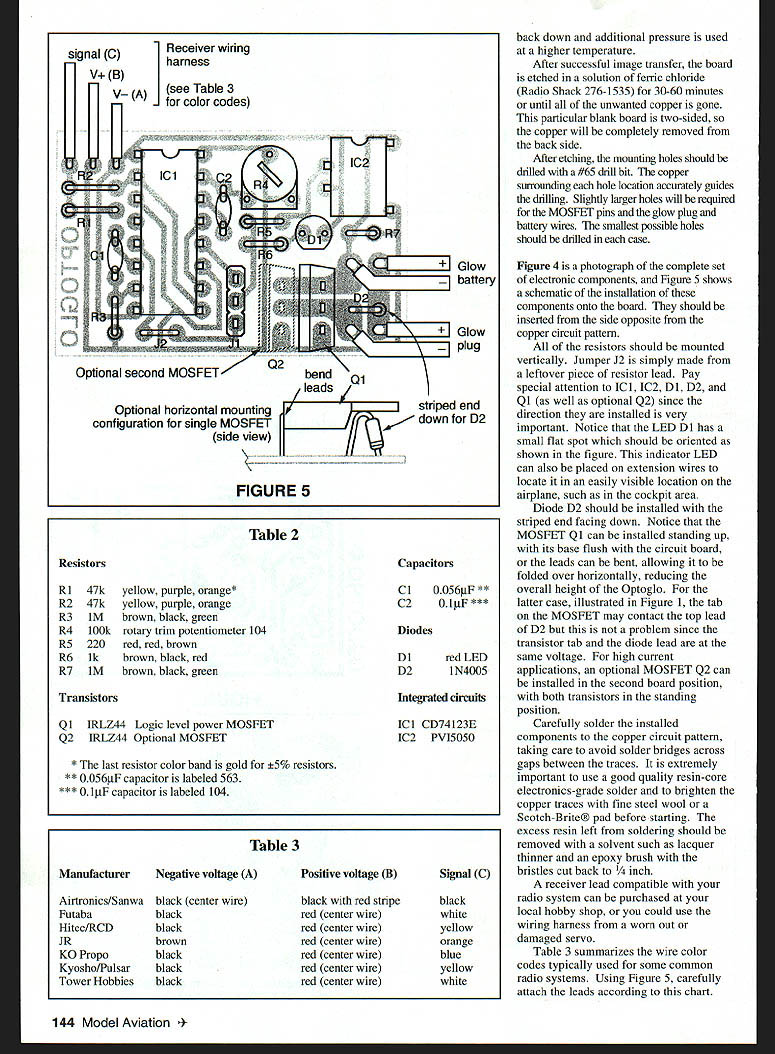
Figure 4 is a photograph of the complete set of electronic components, and Figure 5 shows a schematic of the installation of these components onto the board. Insert components from the side opposite the copper circuit pattern.
All resistors should be mounted vertically. Jumper J2 is simply made from a leftover piece of resistor lead. Pay special attention to IC1, IC2, D1, D2, and Q1 (and optional Q2) since orientation is critical. Note that LED D1 has a small flat spot which should be oriented as shown in the figure. This indicator LED can also be placed on extension wires to locate it in an easily visible position on the airplane (for example, the cockpit area).
Diode D2 should be installed with the striped end facing down. The MOSFET Q1 can be installed standing up, with its base flush with the circuit board, or its leads can be bent to fold it over horizontally, reducing the overall height of the Optoglo. In the folded position the MOSFET tab may contact the top lead of D2; this is not a problem since the transistor tab and the diode lead are at the same voltage. For high-current applications, an optional MOSFET Q2 can be installed in the second board position, with both transistors in the standing position.
Carefully solder the components to the copper circuit pattern, avoiding solder bridges between traces. Use good-quality resin-core electronics-grade solder and brighten the copper traces with fine steel wool or a Scotch-Brite pad before starting. Remove excess resin with a solvent such as lacquer thinner and an epoxy brush with the bristles cut back to 1/4 inch.
A receiver lead compatible with your radio system can be purchased at your local hobby shop, or you can use the wiring harness from a worn-out servo.
Component reference (Table 2)
Resistors
- R1 47 k Ω — yellow, violet, orange*
- R2 47 k Ω — yellow, violet, orange*
- R3 1 M Ω — brown, black, green
- R4 100 k Ω — rotary trim potentiometer 104
- R5 220 Ω — red, red, brown
- R6 1 k Ω — brown, black, red
- R7 1 M Ω — brown, black, green
Transistors
- Q1 IRLZ44 — logic-level power MOSFET
- Q2 IRLZ44 — optional MOSFET
Capacitors
- C1 0.056 µF**
- C2 0.1 µF***
Diodes
- D1 red LED
- D2 1N4005
Integrated circuits
- IC1 CD74123E
- IC2 PV15050
Notes:
- * The last resistor color band is gold for ±5% resistors.
- ** 0.056 µF capacitor is labeled 563.
- *** 0.1 µF capacitor is labeled 104.
Receiver wire color codes (Table 3)
Manufacturer — Negative voltage (A) — Positive voltage (B) — Signal (C)
- Airtronics / Sanwa — black (center wire) — black with red stripe — black
- Futaba — black — red (center wire) — white
- Hitec / RCD — black — red (center wire) — yellow
- JR — brown — red (center wire) — orange
- KO Propo — black — red (center wire) — blue
- Kyosho / Pulsar — black — red (center wire) — yellow
- Tower Hobbies — black — red (center wire) — white
Caution: Airtronics users should note that the V+ and V– wires are reversed in the Airtronics servo harness compared to Futaba, JR, and RCD systems. Since the Airtronics harness has two wires of the same color (black), carefully note which one is the center wire in Table 3.
Figures and wiring schematics
- Figure 5 — installation schematic
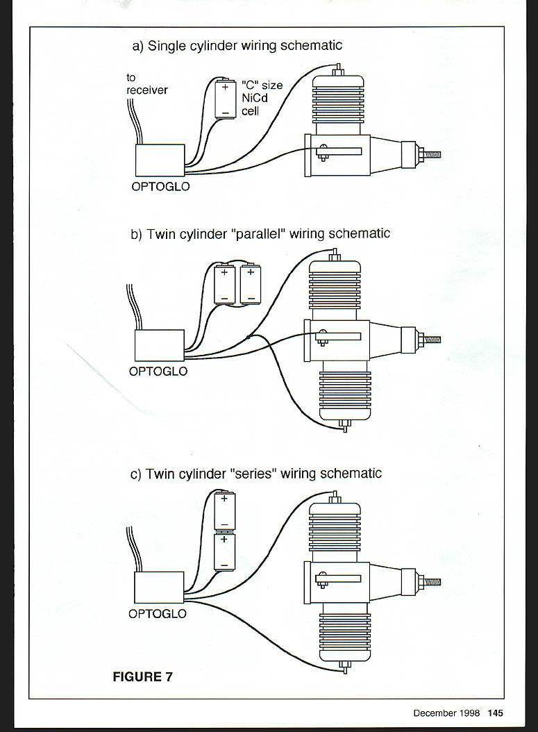
- Figure 7(a) — single-cylinder wiring schematic (to receiver, "C" size NiCd cell)
- Figure 7(b) — twin-cylinder "parallel" wiring schematic
- Figure 7(c) — twin-cylinder "series" wiring schematic
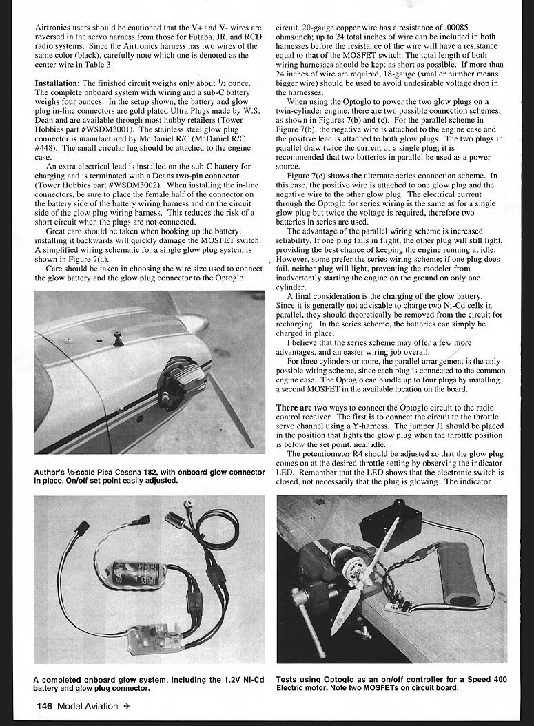
Installation
The finished circuit weighs about 1/2 ounce. The complete onboard system with wiring and a sub-C battery weighs about four ounces. In the setup shown, the battery and glow-plug in-line connectors are gold-plated Ultra Plugs made by W.S. Dean (Tower Hobbies part #WSDM3001). The stainless-steel glow-plug connector is manufactured by McDaniel R/C (McDaniel R/C #448). Attach the small circular lug to the engine case.
Install an extra electrical lead on the sub-C battery for charging and terminate it with a Deans two-pin connector (Tower Hobbies part #WSDM3002). When installing in-line connectors, place the female half of the connector on the battery side of the battery wiring harness and on the circuit side of the glow-plug wiring harness. This reduces the risk of a short circuit when the plugs are not connected.
Great care should be taken when hooking up the battery; installing it backwards will quickly damage the MOSFET switch.
Wire size and length
Care should be taken in choosing wire size between the glow battery and the glow-plug connector to the Optoglo circuit. 20-gauge copper wire has a resistance of 0.00085 ohm per inch; up to 24 total inches of wire can be included in both harnesses before the resistance of the wire equals that of the MOSFET switch. Keep the total length of both wiring harnesses as short as possible. If more than 24 inches of wire are required, use 18-gauge wire to avoid undesirable voltage drop.
Twin-cylinder wiring options
When using the Optoglo to power two glow plugs on a twin-cylinder engine, there are two possible connection schemes:
- Parallel (Figure 7b): The negative wire is attached to the engine case and the positive lead is attached to both glow plugs. The two plugs in parallel draw twice the current of a single plug; use two batteries in parallel as a power source.
- Series (Figure 7c): The positive wire is attached to one glow plug and the negative wire to the other glow plug. The electrical current through the Optoglo for series wiring is the same as for a single plug but twice the voltage is required; use two batteries in series.
Advantages:
- Parallel wiring increases reliability: if one plug fails in flight, the other will still light.
- Series wiring prevents starting the engine on only one cylinder if a plug fails on the ground. Series wiring also allows charging batteries in place.
For three cylinders or more, the parallel arrangement is the only possible wiring scheme, since each plug is connected to the common engine case. Optoglo can handle up to four plugs by installing a second MOSFET in the available board position.
Charging considerations
Since it is generally not advisable to charge two Ni-Cd cells in parallel, they should theoretically be removed from the circuit for recharging. In the series scheme, the batteries can simply be charged in place.
Radio hookup options
There are two ways to connect the Optoglo circuit to the radio-control receiver:
- Y-harness to throttle servo channel — Jumper J1 should be placed so the glow plug lights when throttle position is below the set point (near idle). Adjust potentiometer R4 so that the glow plug comes on at the desired throttle setting by observing the indicator LED. The LED will light whether or not the glow battery is properly charged or the plug is burned out.
- Separate receiver channel — Connect Optoglo to a separate receiver channel. Electronic mixing on the receiver can be used to slave that channel to the throttle or another channel. With a computer radio the mixing can be deactivated if desired and the glow power can be applied with the flip of a switch for the glow channel. This is the preferred setup.
Packaging and vibration protection
Slide the finished circuit into a short length of 1.25-inch-diameter heat-shrink tubing for protection; be careful not to overheat. Cut access holes through the covering to allow set-point adjustments and to move the reversing jumper if necessary. If the circuit is connected to a separate receiver channel, these adjustments may be accomplished by receiver programming.
Wrap the finished circuit in a layer of 1/4-inch latex foam, held with a couple of rubber bands, to shield against engine vibration.
Performance and other uses
Optoglo can be used as an on/off switch for a variety of devices operating with battery voltages up to 50 V. Optoglo can handle 5–6 amps of current with a single MOSFET installed with no heatsinking required. This current handling can be doubled by adding the optional second MOSFET. With aggressive cooling (finned aluminum heatsinks attached to the MOSFET), these devices are rated at continuous currents up to 40 amps each.
Optoglo can also be used as a small, inexpensive switch for Speed 400 and similar electric motors. When controlling an electric motor, always place the reversing jumper in the position nearest the edge of the circuit board so the motor does not start if the transmitter is turned off before the receiver.
Author contact Brent Dane 678 Crane Ave. Livermore, CA 94550
Sources
- Digi-Key Corporation, 701 Brooks Ave. South, Thief River Falls, MN 56701-0677; Tel.: (800) 344-4539.
- Press-n-Peel is manufactured by Techniks and can be ordered from All Electronics Corp., Van Nuys, CA 91411; Tel.: (818) 997-1806.
- Etched printed circuit board: Available from the author; send a check or money order for $10 per board. A complete unassembled kit, without wiring harnesses or battery, can be obtained for $25 (includes postage and handling). Add an additional $5 for a second MOSFET transistor for applications requiring more than six amps of current.
Transcribed from original scans by AI. Minor OCR errors may remain.

