
Orange Box
Clive Smalley
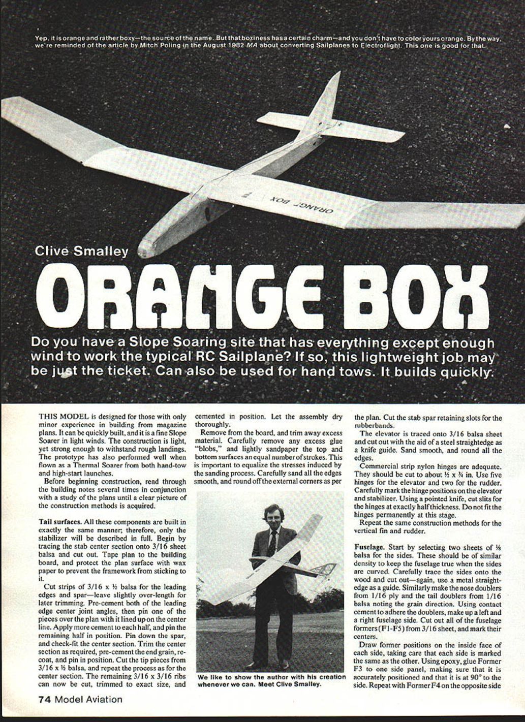
Yep, it is orange and rather boxy — the source of the name. But that boxiness has a certain charm — and you don't have to color yours orange. By the way, we're reminded of the article by Mitch Poling in the August 1982 MA about converting sailplanes to Electroflight. This one is good for that.
Do you have a slope-soaring site that has everything except enough wind to work the typical RC sailplane? If so, this lightweight job may be just the ticket. It can also be used for hand tows. It builds quickly.
This model is designed for those with only minor experience in building from magazine plans. It can be quickly built, and it is a fine slope soarer in light winds. The construction is light, yet strong enough to withstand rough landings. The prototype has also performed well when flown as a thermal soarer from both hand-tow and high-start launches.
Before beginning construction, read through the building notes several times in conjunction with a study of the plans until a clear picture of the construction methods is acquired.
Tail surfaces
All tail components are built in exactly the same manner; therefore only the stabilizer will be described in full.
Begin by tracing the stab center section onto 3/16" sheet balsa and cut out. Tape the plan to the building board, and protect the plan surface with wax paper to prevent the framework from sticking to it.
Cut strips of 3/16" x 1/2" balsa for the leading edges and spar — leave slightly over-length for later trimming. Pre-cement both of the leading-edge center joint angles, then pin one of the pieces over the plan with it lined up on the center line. Apply more cement to each half, and pin the remaining half in position. Pin down the spar, and check-fit the center section. Trim the center section as required, pre-cement the end grain, recoat, and pin in position. Cut the tip pieces from 3/16" x 1/2" balsa, and repeat the process as for the center section. The remaining 3/16" x 3/16" ribs can now be cut, trimmed to exact size, and cemented in position. Let the assembly dry thoroughly.
Remove from the board and trim away excess material. Carefully remove any excess glue "blobs," and lightly sandpaper the top and bottom surfaces an equal number of strokes. This is important to equalize the stresses induced by the sanding process. Carefully sand all the edges smooth, and round off the external corners as per the plan. Cut the stab spar retaining slots for the rubber bands.
The elevator is traced onto 3/16" balsa sheet and cut out with the aid of a steel straightedge as a knife guide. Sand smooth, and round all the edges.
Commercial strip nylon hinges are adequate. They should be cut to about 1/2" x 3/8". Use five hinges for the elevator and two for the rudder. Carefully mark the hinge positions on the elevator and stabilizer. Using a pointed knife, cut slits for the hinges at exactly half thickness. Do not fit the hinges permanently at this stage.
Repeat the same construction methods for the vertical fin and rudder.
Fuselage
Start by selecting two sheets of 1/8" balsa for the sides. These should be of similar density to keep the fuselage true when the sides are curved. Carefully trace the sides onto the wood and cut out — again, use a metal straightedge as a guide. Similarly make the nose doublers from 1/16" ply and the tail doublers from 1/16" balsa noting the grain direction. Using contact cement to adhere the doublers, make up a left and a right fuselage side. Cut out all of the fuselage formers (F1–F5) from 3/16" sheet, and mark their centers.
Draw former positions on the inside face of each side, taking care that each side is marked the same as the other. Epoxy glue Former F3 to one side panel, making sure that it is accurately positioned and at 90° to the side. Repeat with Former F4 on the opposite side.
Join the two sides together by epoxying the edges of Formers F3 and F4 and bringing the sides together. Check to make sure the formers line up with the marked positions. Place the fuselage upright on the building board; the bottom edges of the fuselage sides should contact the board along their full lengths to keep the fuselage free from twists. Leave it to cure.
Select a sheet of 3/16" balsa at least 2" wide for the fuselage bottom. Mark the center line full length using a long straightedge; accuracy of this line will determine the accuracy of the fuselage.
Apply epoxy to Former F1 and fit it in. Hold in position with a rubber band around the nose; sight along the bottom and adjust until the nose is straight. Repeat for the aft end. Apply epoxy to Formers F2 and F5, and fit them in position.
When the glue on the formers has cured, the basic fuselage can be glued to the bottom sheet with contact cement. Double check to ensure that the center lines of the formers are all on the line drawn on the inside face of the bottom sheet. Care here will give the desired straight fuselage.
For additional strength, run a fillet of white glue along the corner joints.
Assemble the 1/16" sheet top decking by gluing together sufficient sheet widths to make up the required length. (Do not make the top deck with the grain lengthwise, as this won't provide enough strength.) The top decking can now be glued on. When dry, trim off the excess wood. Also trim the bottom sheet flush with the sides. At this time, leave the edges square.
Glue the 3/8" x 1/4" wing runners in position. The inside of the nose compartments can now be lined with lightweight fiberglass cloth and resin. Draw around the underside of the nose area to make a 1/32" ply bottom reinforcement; cut away and glue in position with contact cement. The bottom corners should be lightly rounded, but don't overdo the rounding as it may weaken the side/bottom joint. Cement together laminations of sheet balsa for the nose block (leave oversize), and epoxy to Former F1.
Cut out and epoxy the 1/8" ply hatch retaining plate in position. Make the hatch from 3/32" sheet balsa — again leave oversize at the sides, and spot-glue in place. Carve and sand the hatch nose block to shape. Cut away the hatch about 1" from the front with a razor saw. Glue this small piece back on the fuselage.
Cut out the 1/16" ply front hatch retaining plate, and trim it to a snug fit for sideways location between the sides. Epoxy the 1/16" ply to the hatch bottom face.
Spot-drill through the hatch into the rear 1/8" ply retaining plate for the wood screw attachment. Drill holes for the wing and elevator dowels, placing scrap block against the inside faces to prevent splitting as the drill breaks through.
Epoxy the fin to the top decking, making sure that it is vertical and on the fuselage center line. Add triangular reinforcing fillets to each side. Test-fit the stabilizer, using small rubber bands on each side. Hinge the rudder and elevator in place. Be sure that there is adequate clearance for both the rudder and elevator when they are at full throw. If necessary, trim wood from the rudder bottom edge. Remove the rudder and elevator for now, and permanently attach the hinges after covering the surfaces.
Wing
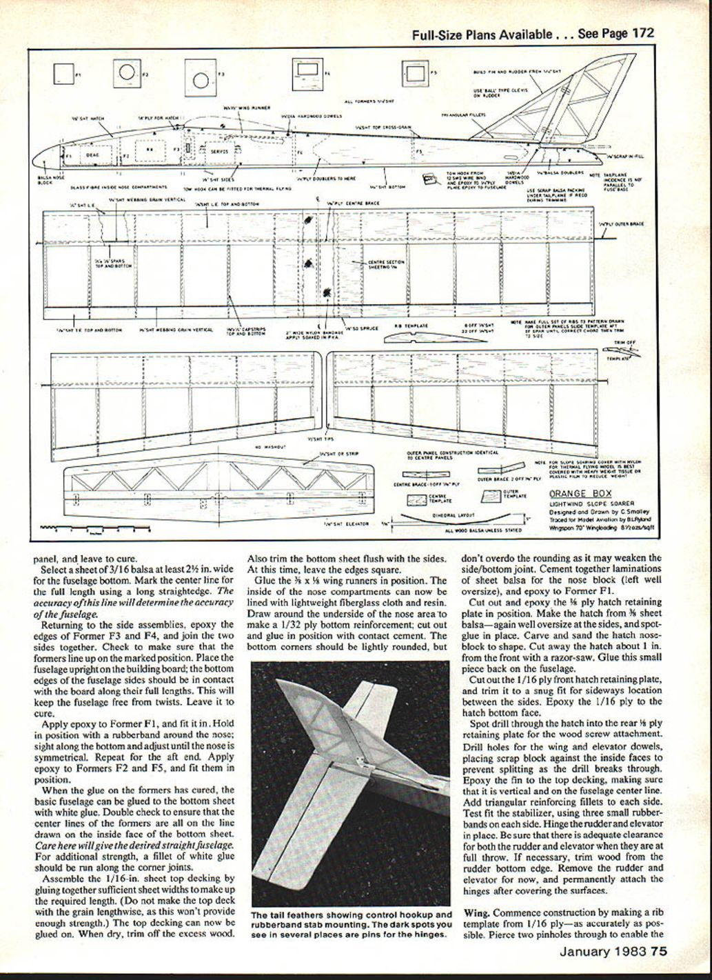
Commence construction by making a rib template from 1/16" ply — as accurately as possible. Pierce two pinholes through to enable the template to be pinned to the sheet balsa when making individual ribs. These can be made either by carefully cutting with a modeling knife directly around the template or by drawing around the template with a pencil or ball-point pen, cutting out free-hand, and sanding to match the template. The tip ribs of different chord lengths are made as per the plan sketch. Make a complete set before beginning gluing operations. Prepare the leading and trailing edges by carefully cutting against a straightedge. Make the upper leading edge sheets oversize to allow for the rib curvature. Finally, cut out the ply dihedral braces and template.
The wing is constructed in four separate panels; the procedure is identical for each. The dihedral brace slots are cut later.
Pin down the lower leading and trailing edge sheets. The lower cap-strips can either be pinned down now or added when the structure is removed from the board. Cut the lower spar over-length and glue it in position along the rear edge of the sheet. Check for straightness.
Fit each of the ribs in position, carefully setting them square and vertical (or inclined to the dihedral template for the end ribs). Add the top spar and the leading edge strip, gluing to the sheet and each rib nose. Do not shape the leading edge until later. Glue on the rear upper trailing edge sheet, pinning down well especially along the rear joint. Fit the spar webbing and the trailing-edge webbing with the grain running vertically. Let this assembly dry for 24 hours.
When dry, remove from the building board, and sand the leading-edge strip to match the rib curvature. Do not round off the front edge. Re-pin the panel to the board, and glue on the upper leading-edge sheet and cap-strips. The panel should again be left pinned down for 24 hours. This completes the basic wing panel construction.
Trim away any surplus sheet and spar ends, and sand the leading edge to a nice round shape. The tip blocks can now be added, carved, and sanded to shape.
When all four panels are complete, cut the slots for the dihedral braces in each of the end ribs. Epoxy the outer braces to the center panels. Weight down the center panel to the building board, and apply epoxy to the brace and both end ribs. Position the outer panel, and block it up to the correct dihedral angle. Repeat this procedure with the opposite panels. When cured, repeat for the center joint, weighting down one wing half and blocking up the other. Leave to cure. Lightly sand the whole wing.
Finally, cut a 2"-wide bandage of nylon to wrap around the wing, with about 1/8" of overlap. Mask around the wing with tape, leaving the center sheeting exposed about 1 1/4" on each side from the center. Apply white glue to the bottom. Starting at about 1/2" to 1" from the trailing edge, position the nylon and pin it. Work around the wing applying more white glue and gently pulling the nylon taut. Smooth out any air bubbles. Overlap any surplus and re-pin. When the glue has dried, apply more on the outside, smoothing down with a finger until all of the nylon weave is filled. When dry, remove the tape masking, and lightly sand the area.
Covering and finishing
There are several suitable covering materials: nylon, silk, tissue, and plastic film. The prototype was covered with nylon, since it was to be used mainly as a slope soarer. If using tissue, use heavyweight on the wings and lightweight for the remainder.
Radio installation
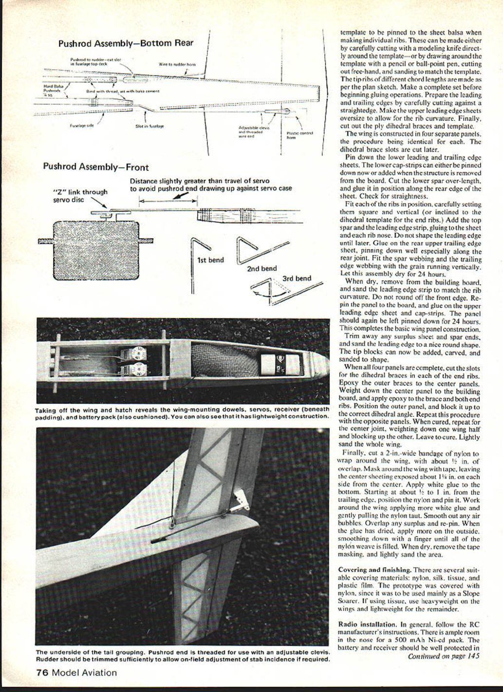
In general, follow the RC manufacturer's instructions. There is ample room in the nose for a 500 mAh Ni-Cd pack. The battery and receiver should be well protected in sponge rubber. The switch can be mounted just behind F3. Pushrods can be either hard balsa or tube-and-cable with adjustable clevises for fixing to variable-throw horns.
Flying
It is easier to learn to fly this type of model from a slope, but do enlist the help of an experienced pilot if this is your first RC model. This form of flying gives more airspace beneath the model and, hence, more time to correct errors. Longer flight times also help give continuity to embryo piloting—without the panic of constant landings from hand-tow or high-start launching.
Choose a calm day for the initial hand test glides, which should take place on a flat grass field. Check the center of gravity position, and start with the stabilizer packed up under the leading edge with a piece of 1/16" x 3/16" x 1-1/2" balsa. Gently throw the model into the wind—aimed at a point about 30 ft. ahead, and have the RC switched ON. However, don't use the RC unless something is seriously wrong, as it could give a false indication of the flight path.
Adjust the nose weight or elevator incidence until a steady descent is achieved with the elevator at neutral. When satisfied, first flights from the slope may be attempted. Wait for a day with a gentle breeze blowing directly at the slope face. Check to see that the controls are working correctly, and launch the model—wings level and nose slightly down—with a smooth push and follow-through. Keep the model heading straight out from the slope. If the model does not gain height, or if it sinks below the crest height, do not attempt a turn until at least 50 yards in front of the slope—then make a landing at the bottom of the hill. Never turn back toward the slope unless well above crest height, and then only to make a landing on the hill.
Turns should always be made into the wind, and progress forward should be made in a series of "S" turns, as the model is never more than sideways to the hill. When the model is correctly trimmed, it will slowly penetrate into the wind and gain height in a steady, level manner.
If the conditions vary during an afternoon's flying, don't be afraid to land and adjust the stabilizer incidence or nose weight to give optimum performance. Initially it is always safer to fly the model in a slightly nose-heavy condition. The model will then fly faster and give good control response.
For hand-tow flying, use a 75 to 100-ft length for first flights. Develop an agreed-upon signaling system with your helper before any flights are attempted. Test the controls, raise the model to head height with the wing level. As your helper begins to run, take several steps forward, and launch the model. Don't throw it hard; a gentle push, almost allowing it to be pulled from your hand, is all that is necessary. Your helper should initially run fairly hard to get the model climbing.
A gentle touch of elevator will help initiate the climb. Once the climb is steady, your helper should adjust his running speed to maintain a steady pull on the line. Concentrate on steering along a straight flight path, and leave elevator alone. When the model reaches the crest of the flight path, your helper should ease off running and allow the model to fly over his head, disengaging itself from the towline.
In an emergency with hand towing, if the model veers sideways immediately after launch, your helper should immediately release the line, even throwing it towards you if necessary. Quick action will be needed to save the model. When released, it will slow down to normal flying speed, and it then can be controlled.
I do not recommend high-start launching until a lot of flying experience has been gained, as once launched the model is committed until the power of the elastic has been exhausted.
The prototype has achieved many hours of flying time, mainly from the slope, repaying many times over the effort put into its construction.
I do hope you enjoy both building and flying this model and that you go on to more advanced designs.
Transcribed from original scans by AI. Minor OCR errors may remain.

