
ORCA
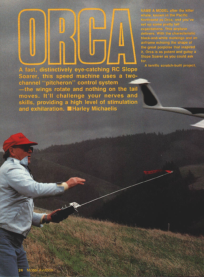
A fast, distinctively eye-catching RC slope soarer, Orca is a speed machine that uses a two-channel "pitcheron" control system — the wing panels rotate and nothing on the tail moves. It will challenge your nerves and skills, providing a high level of stimulation and exhilaration.
Harley Michaelis
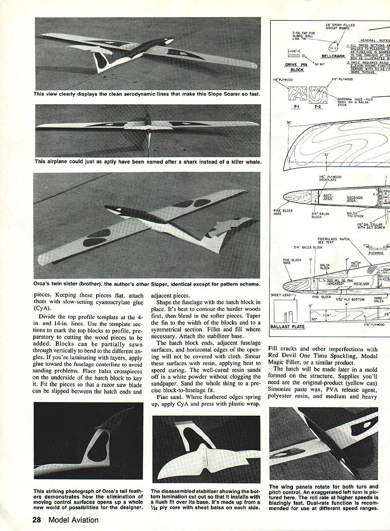
Name a model after the killer whale, known in the Pacific Northwest as Orca, and you've set up some tall expectations. This airplane delivers. With characteristic black-and-white markings and an airframe echoing the shape of the great porpoise that inspired it, Orca is a potent and gutsy sloper.
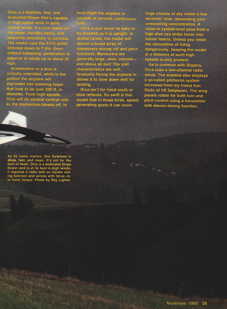
Built as a scratch project, Orca is a fearless, fast, and dedicated sloper capable of high-speed work in quite strong winds. It's rock stable on the slope, handles easily, and responds beautifully to controls. The model uses the E374 airfoil slimmed down to 7.5%. Even without ballasting, penetration is superior in winds up to about 35 mph.
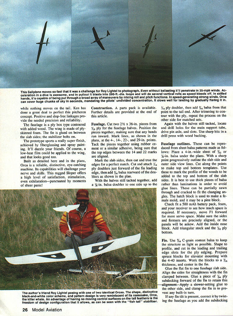
Acceleration in a dive is virtually unbridled; in the pullout the airplane will skyrocket into towering loops that look to be over 200 ft. in diameter. From high speeds, Orca will do several vertical rolls as momentum bleeds off. In level flight the airplane is capable of smooth, continuous rolls.
Orca is about as easy to fly inverted as it is upright. In skilled hands, the model delivers a broad array of maneuvers mixing roll and pitch functions. Maneuvers are generally large, wide, smooth—and above all fast. Stall characteristics are soft; gradually flaring the airplane in allows it to slow down well for landing.
Orca isn't for timid souls or slow reflexes. So swift is this model that in brisk, speed-generating gusts it can cover huge chunks of sky within a few seconds, demanding unwavering concentration. A close-in eyeball-level pass from a high dive can strike terror into fainter hearts. Unless you relish living dangerously, keeping the model at a distance at such high speeds is prudent.
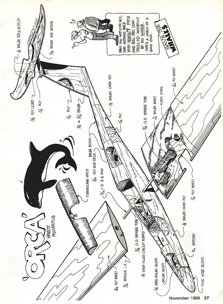
As is common with slopers, Orca uses a two-channel radio setup. It employs a so-called pitcheron system borrowed from Ken Stuhr of VS Sailplanes: the wing panels rotate for both turn and pitch control using a transmitter with elevon-mixing function. While nothing moves on the tail, Ken has perfected this pitcheron concept. Positive, slope-free linkages provide the needed precision and reliability.
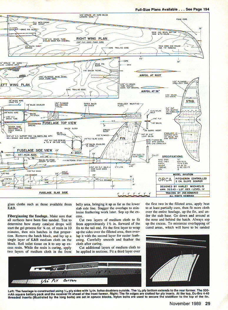
The fuselage is a ply-box type contoured with added wood. The wing is ply-skinned foam. The fin is glued on between the slab sides; the stabilizer bolts on.
The prototype sports a super finish achieved by fiberglassing and spray painting. It dazzles. A low-heat film could also be applied to the wing for a good appearance.
Built as detailed here and in the plans, Orca is a reliable, distinctive, eye-catching machine. Its capabilities will challenge your nerve and skills. This rugged sloper offers a high level of satisfaction, stimulation, even exhilaration—punctuated by moments of sheer panic.
Construction
A parts pack is available. Further details are provided at the end of this article.
Fuselage
- Cut two 2-1/2 x 36-in. pieces from 1/16-in. ply for the fuselage halves. Position the pieces together, making sure any bends run inward. Mark lines at the 4-, 14-, 22-, and 29-in. points as shown on the plans. Tack the pieces together using rubber cement or a similar adhesive, ensuring the top edges between the 14- and 22-in. marks are aligned.
- Mark the slab sides, then cut and true the edges for a perfect match. Cut and attach 1/16-in. ply doublers just forward of the fin leading edge and add 1/16-in. balsa rearward of the doublers as shown on the plan.
- With the halves still tacked together, add 1/8-in. balsa doublers to one side up to the 1/16-in. ply doubler, then add 1/8-in. balsa from that point to the tail end. After trimming to contour the ply, repeat on the other side for matched sets.
- Keeping pieces flat, attach them with slow-setting cyanoacrylate glue (CyA).
Top-blocks and contours:
- Divide the top-profile template at the 4-in. and 14-in. lines. Use the template sections to mark the top blocks' profiles preparatory to cutting the wood pieces to be added. Blocks can be partially sawed through vertically to bend different angles when laminating layers; apply glue toward the fuselage.
- Fit top blocks to the slab sides and finish sanding to shape. Add the hatch block and plywood subdecking, trimming as required for a smooth contour. Check final fit of battery, receiver, and foam; relocate F1 forward if more servo space is necessary.
Hatch and formers:
- Place balsa crosspieces on the underside of the hatch block to key it. Fit pieces so a razor saw blade can be slipped between the hatch ends and adjacent pieces.
- Shape the fuselage with the hatch block in place, contouring harder woods first then blending in softer pieces. Taper the fin to the width of the blocks and to a symmetrical section. Fillet and fill where necessary. Attach the stabilizer base.
- Fine sand and fair all joints before sheeting and glassing. Fill cracks and imperfections with spackling compound or model filler.
Final checks:
- Check fit of a 500-mAh battery pack, foam, and receiver to determine space requirements. If necessary, move F1 forward for servo space. Make sure sides and formers are precisely aligned or the panels will be askew.
Fin
- Use 1/16-in. C-grain contest balsa to keep the structure light. Shape to profile and cut leading- and trailing-edge slots for the ply edging.
- Prepare spruce blocks for elevator mounting with 4-40 inserts. Work the blocks to a 3/16-in. thickness and center in the fin.
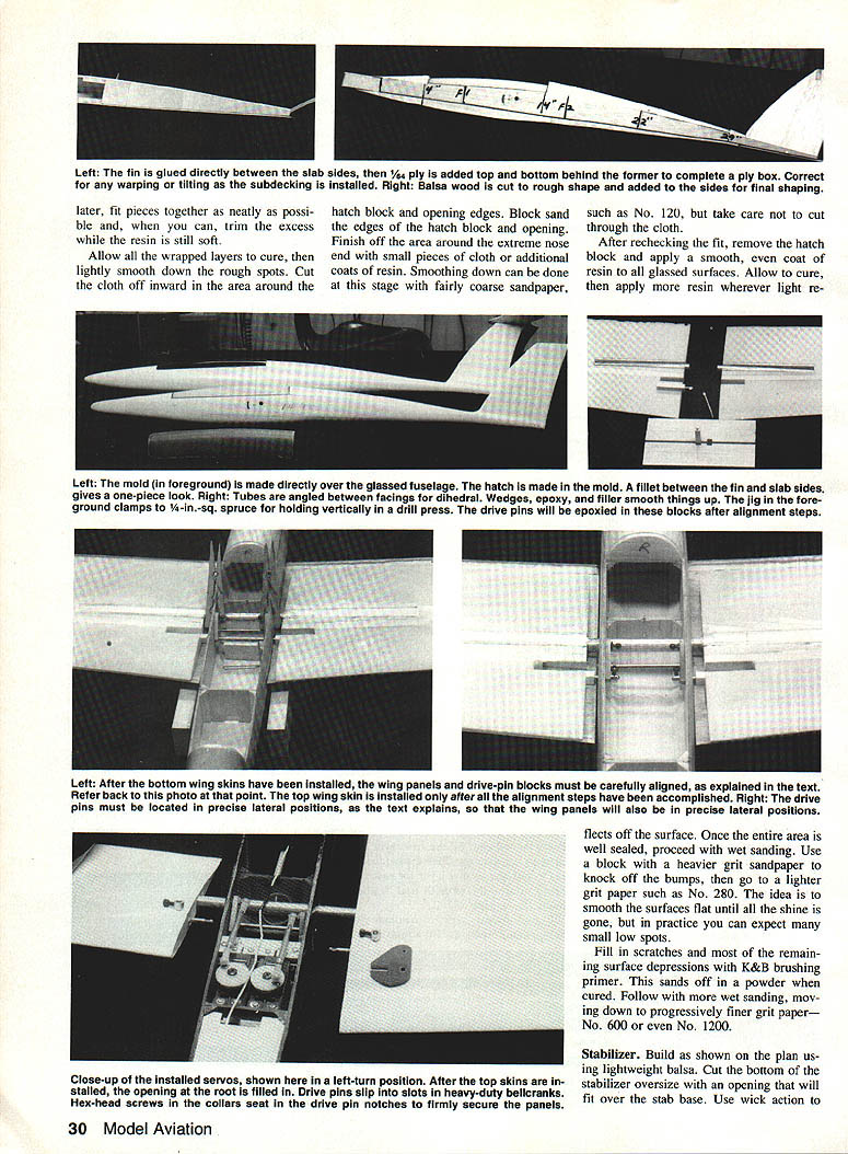
- Glue the fin to one fuselage slab side. Align the sides for straightness with the fin clamped between them. Glue a piece of 1/16-in. ply subdecking forward of the fin to retain alignment.
- Apply a slower-setting glue to the other side and clamp the fin to prevent built-in turn. If any fin tilt is present, correct it by twisting the fuselage as you add the subdecking.
Fiberglassing the fuselage
- Make sure all surfaces have been fine sanded. Test catalyst drops to determine the gel rate for 1/4 oz. of resin in 10 minutes, then mix batches accordingly.
- Remove the hatch block and lay up a single layer of medium-weight cloth on the block. Roll out tissue on it to sop up excess resin. While the resin is curing, apply two layers of medium cloth in the front belly area, bringing it up as far as the lower slab-side line. Stagger overlaps to minimize feathering work later and sop up excess.
- Cut two layers of medium cloth to fit from approximately 1-1/2 in. forward of the fin to the tail end. Fit the first layer to wrap up the sides over the filleted area, then overlap it with the second layer for easier feathering. Carefully smooth and feather the cloth after curing.
- Fit additional layers in sections: a third layer over the filleted area, use heat to at least partially cure before overlapping, then fit more cloth over the entire fuselage, up the fin, and under the stab base. Work down and around the nose and behind the hatch. Always sop up the excess resin.
- Allow wrapped layers to cure, then lightly smooth rough spots. Cut cloth inward around the hatch block and opening edges, block-sand the edges, and remove the hatch block.
- Apply a smooth, even coat of resin to all glassed surfaces. After curing, wet sand progressively from coarse (No. 120) to finer grits (No. 280, No. 600 or No. 1200) until all shine is gone. Fill scratches and low spots with K&B brushing primer and repeat wet sanding as needed.
Stabilizer
- Build the stabilizer from lightweight balsa as shown on the plan. Cut the bottom oversize with an opening to fit over the stab base.
- Use wick-action CyA to glue the center core to the bottom and trim to the core edges. Add the top and shape to a symmetrical airfoil, tapering toward the tips. Glass with light cloth.
- To find flaws before final painting, spray a very light temporary coat of cheap white quick-dry high-gloss enamel and view in low-angle light. Fill larger flaws with primer and tiny pits with thin CA. Remove the temporary coat with acetone or lacquer thinner before final finishing.
Fiberglass hatch
- Outline the hatch with 1/8-in. trim tape applied 3/8 in. away from the hatch block on the fuselage to allow for shrinkage. Apply wax and PVA release agent to surfaces where the hatch block fits; when dry, fit the block, wax the block and fuselage a couple of inches beyond the tape edge, and apply PVA overall.
- Size one layer of medium cloth and four of heavier cloth so the mold will extend about an inch beyond the tape. For the mold, laminating resin (e.g., Evercoat No. 561) has an advantage because it cures tacky and bonds cloth; K&B resin may be used.
- Use the 10-minute gel rate. Coat the protected structure with resin, cure, position and coat a light layer of glass cloth, then add four heavier layers in succession. Carefully separate the well-cured mold and hatch block, wash off PVA, and sand wax from the fuselage.
- Wax and apply PVA to the mold. Brush on K&B or laminating resin and progressively lay up one layer of medium cloth and two of heavier. After curing, remove the mold, trim the hatch to the tape line, and fine-fit it to the fuselage.
- Vertically position the hatch ends on 1/8-in. balsa and mark them on the inside. Glue these half-moon rests to the fuselage to key the hatch. Add a block with a small hook attached for hatch retention.
Wing
- No ballast tubes are used; ballast plates of sheet lead can add over 2 lb. if desired.
- If main tube facings are to extend to the core root, roughen the tube surface and epoxy the facings so they fit snugly against the tubes without protruding above the core surface.
- To impart dihedral, angle the tubes vertically between the facings and adhere with Zap. Prepare wedge-shaped balsa pieces to fill under and over the tubes and epoxy them in place. Tape fillets until resin cures; remove tape after curing.
- The cores in the parts pack are cut to the wing leading edge (LE) but end 1/2 in. in front of the wing trailing edge (TE). Use two 1/4-sht. sheets of 1/8-in. plywood to make the wing skins. Cut bottom skins from separate sheets; align them with the core LE and extend them 1/4 in. beyond the core root. Precisely mark the tip contour.
- On the inside, evenly feather the last 1/4 in. of the trailing edge down to the bottom lamination. Trim and contour the core strip as a base for the top skin, leaving about 1/8 in. for balsa edging at the tip perimeter. Attach the bottom skins with epoxy.
- Heavy-duty matching bellcranks from the parts pack are essential. Open the 1/4-in. hole with a No. 23 bit and gently tap in a 3/16-in. length of 5/32-in.-I.D. brass tube as a bearing to prevent bellcrank wobble.
- Prepare the 1-ft.-long 5/16-in. main tube to protrude 1/2 in. at either side in the fuselage. Similarly size the 1/8-in. pivot wire and associated hardware. Prepare 1/4-in.-sq. by 1-1/4-in.-long spruce blocks with center-drilled holes; use a jig to hold blocks vertically for drilling.
- Wing alignment: align at 0-0 with respect to the fuselage under the fin. Place a straightedge under the fin, extend it to mark a 0-0 line in the wing area. Mount wings so bottom wing skins are parallel to the fuselage sides with 1/2-in. clearance for rotation.
- Drive-pin and bellcrank setup:
- Cut a 4-1/2-in.-long piece of 3/8-in. wire and run it through the bellcrank slots; add the drilled blocks. Clamp bellcranks upright in neutral with clothespins. Block up the wing panels from the underside and place a 3/8-in. thick block under the long wire to square holes in the drive pin blocks with the main rod.
- When panels are at 0-0, the long wire (and hence drive pins) should center vertically in the arcs. Rotate one panel so the leading and trailing edges of the skin are parallel to the 0-0 line. Fit facings between a layer of foam and the block, push the wire down, and tack in the drive pin block using CyA or quick-set epoxy. Allow about 1/8 in. between the outboard end of the block and the end of the foam slot. Align panels by eye and tack the other block in place.
- Remove wings and wire. Secure and finish the drive pins so that with collars on the pins protrude about 3/16 in. beyond the blocks. After mounting everything in place, push bellcranks completely into neutral and block them so the wire lays in its groove. Cut the drive pins even with the collars and peen them over to prevent withdrawal.
- To define lateral location of each drive pin, make a cut in the drive-pin end and epoxy in a scrap of spruce so it butts against the end. Rough up each pin and attach with epoxy making sure the notch faces up. Zap the pivot wire and the main tube in place and add epoxy putty around the inside of the tube.
- Top skins: cut the top wing skin to the extreme leading edge, extending it at the root to match the bottom skin and about 1/8 in. beyond the latter at the trailing edge and tip. Edge the bottom skin with balsa, beveling it so the top skin will form a fine edge. Shape the foam inward as a rounded base for the top skin in the tip area. Join the top skins to the cores as far as the 32-in. mark.
- When cured, invert the panel. Wick-glue the skins together with CyA along the trailing edge to the 32-in. point, pressing with a straight stick only on the last 1/4 in. of the bottom skin.
- Wing tips: experiment by pressing and lifting the tip skins together at various spots to find the optimum attach point before gluing. Aim for a nice line around the edge and a tight, smooth fit in the raked tip. Wick-join the tips with CyA and trim excess top skin.
- Remove 3/16 in. from the panels at the leading edge, then add and shape the LE. Fill in at the roots with scrap wood and epoxy putty; make sure blocks and pins are buried in the epoxy.
Fiberglassing the wing
- Prepare panels by fine sanding and wiping clean. Cut light glass cloth to cover a panel in one piece wrapped around the leading edge. Position the piece on top with the excess extending forward.
- Using a wide brush for quick application, smear resin everywhere except the area around the leading edge. Work from the center outward and pull the cloth from both ends to smooth out puckers. Brush from front to back as well, ensuring the entire area is wetted.
- Slit the cloth where the tip curves. Use a roll of tissue to sop up excess resin until no wet look remains. Allow the resin to cure to the point the panel can be handled, then invert and follow the same procedure for the other side. Pull cloth rearward to smooth around the LE and wrap the LE separately when the panel can be handled on its edge.
- Sand, recoat, and prepare for painting in the same way as the fuselage.
Painting
- Finish sand, dust off, and tack all surfaces. Choose a clean environment for spray painting and drying.
- Durable epoxies such as those made by K&B adhere well to properly prepared surfaces. A white base yields a fine-looking finish when trim colors are added.
- Among inexpensive brands, the Dutch Boy fast-drying spray enamel ("The Fresh Look") produces a soft, fine fan-shaped spray that works well. Keep moving as you spray and overlap evenly. Apply 8–10 light coats a few minutes apart for good coverage. Dutch Boy white enamel is No. 3725; black is No. 3726. Wait five days as instructed by the manufacturer, then mask and add trim colors.
- If the paint allows, well-cured surfaces can be worked to a deep sheen using polishing compound and wax (e.g., Simoniz) to minimize skin friction.
Servos and linkages
- Use servos with 50 in.-oz. torque or better and mount them firmly. Size and adjust connecting links so wing panels are at 0-0 alignment with trim tabs set neutral.
- Check that the right wing moves up as the left moves down for a left turn, and that both wings move up at the front with up elevator. If not, correct by switching servo plugs.
- Ensure bellcrank ball links are approximately vertical for similar motion each way.
Initial flight testing
- Use a dual-rate transmitter if available. Set the transmitter at the low rate and adjust wing motion for about 3/8 in. of both upward and downward elevator response at the trailing edge. You should have approximately 3/8 in. on the high elevator setting and similarly 3/8 in. for aileron on low rate and 1 in. or more on high. If you don't have dual rate, set wing and aileron responses to the suggested low-rate figures.
- Find a long stretch of lawn, preferably with a rise or knoll. First objective: trim for level flight without worrying about turn. Due to the long stabilizer moment arm, pitch action is soft, but you must get the model to flying speed quickly—don't be timid. Heave it straight out and a bit nose-up, hard!
- Adjust trim tab as necessary for level flight, then mark the fuselage where it meets the wing trailing edge. Center the trim tab and adjust the linkage for the marked spot. The goal is to have the wing as near to 0-0 neutral as possible for maximum penetration. If necessary, put a shim under the stab at the front or rear.
- Check roll rate using small inputs at first. The panel rotation should make for smooth, steady turns. Excess rotation causes rocking typical of overcontrol.
- At the slope, launch Orca aggressively in winds of 15 mph or higher. Things get interesting when turbulence reaches 25 mph; at gusts of 35 mph or better, full attention is required. After an hour of airtime you should be fairly confident. Keep the plane up high and flat at high airspeeds. Experiment with CG farther aft for quicker pitch response and with ballast in heavier winds.
Soaring high aloft and resplendent in its black-and-white killer-whale markings, Orca does its builder/flyer proud.
Parts pack and ordering
- The parts pack includes precision-cut blue foam cores, special bellcranks, and a 1-ft.-long 5/16-in. stainless steel rod.
- Order from VS Sailplanes, 2317 N. 63rd, Seattle, WA 98103. Price including shipping is $24.95.
- For airfoil coordinates, send a preaddressed, stamped envelope to Harley Michaelis, 26 S. Roosevelt, Walla Walla, WA 99362; enclose a loose, unglued 25¢ stamp to cover photocopying costs.
Transcribed from original scans by AI. Minor OCR errors may remain.

