
OSPREY 900
It is one thing to build a sailplane from a manufactured kit, but quite another to design and build one from scratch. Scratch building can be defined by those ominous words from your boss: "What are you working on so hard?" He peers into your calculator and writing pad filled with strange (to him) numbers and planform scribblings and asks, "Why are you dividing everything by 144?" Scratch building is also cutting your own wing ribs, learning from your mistakes, and ignoring negative comments about your dream ship. Needless to say, scratch building, when successful, can be the most satisfying aspect of modeling. I recommend it to anyone who is looking for a way to release their creative moods.
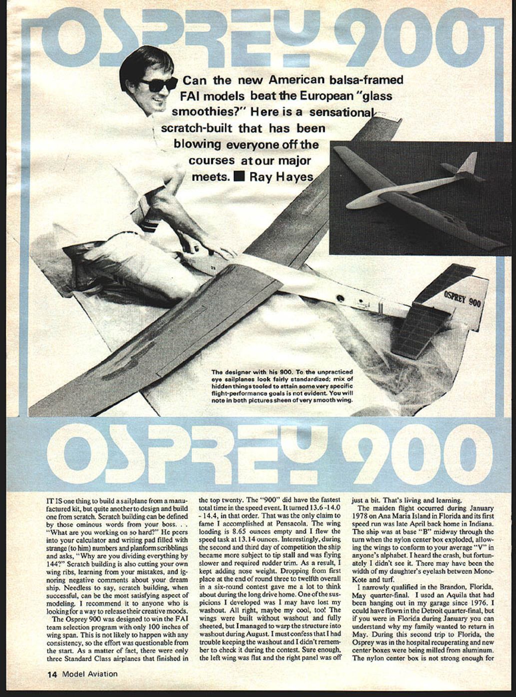
The Osprey 900 was designed to win the FAI team selection program with only 100 inches of wingspan. This is not likely to happen with any consistency, so the effort was questionable from the start. As a matter of fact, there were only three Standard Class airplanes that finished in the top twenty. The "900" did have the fastest total time in the speed event. It turned 13.6 - 14.0 - 14.4, in that order. That was the only claim to fame I accomplished at Pensacola. The wing loading is 8.65 ounces empty and I flew the speed task at 13.14 ounces per sq. ft. Interestingly, during the second and third day of competition the ship became more subject to tip stall and was flying slower and required rudder trim. As a result, I kept adding nose weight. Dropping from first place at the end of round three to twelfth overall in a six-round contest gave me a lot to think about during the long drive home. One of the suspicions I developed was I may have lost my washout. All right, maybe my cool, too! The wings were built without washout and fully sheeted, but I managed to warp the structure into washout during August. I must confess that I had trouble keeping the washout and I didn't remember to check it during the contest. Sure enough, the left wing was flat and the right panel was off just a bit. That's living and learning.
The maiden flight occurred during January 1978 on Ana Maria Island in Florida and its first speed run was late April back home in Indiana. The ship was at base "B" midway through the turn when the nylon center box exploded, allowing the wings to conform to your average "V" in anyone's alphabet. I heard the crash, but fortunately I didn't see it. There may have been the width of my daughter's eyelash between MonoKote and turf.
I narrowly qualified in the Brandon, Florida, May quarter-final. I used an Aquila that had been hanging out in my garage since 1976. I could have flown in the Detroit quarter-final, but if you were in Florida during January you can understand why my family wanted to return in May. During this second trip to Florida, the Osprey was in the hospital recuperating and new center boxes were being milled from aluminum. The nylon center box is not strong enough for FAI speed task. However, it is very good for normal thermal competition. Upon my return I used a 1/4-in. drill to remove the nylon box from the fuse and replaced it with the aluminum box.
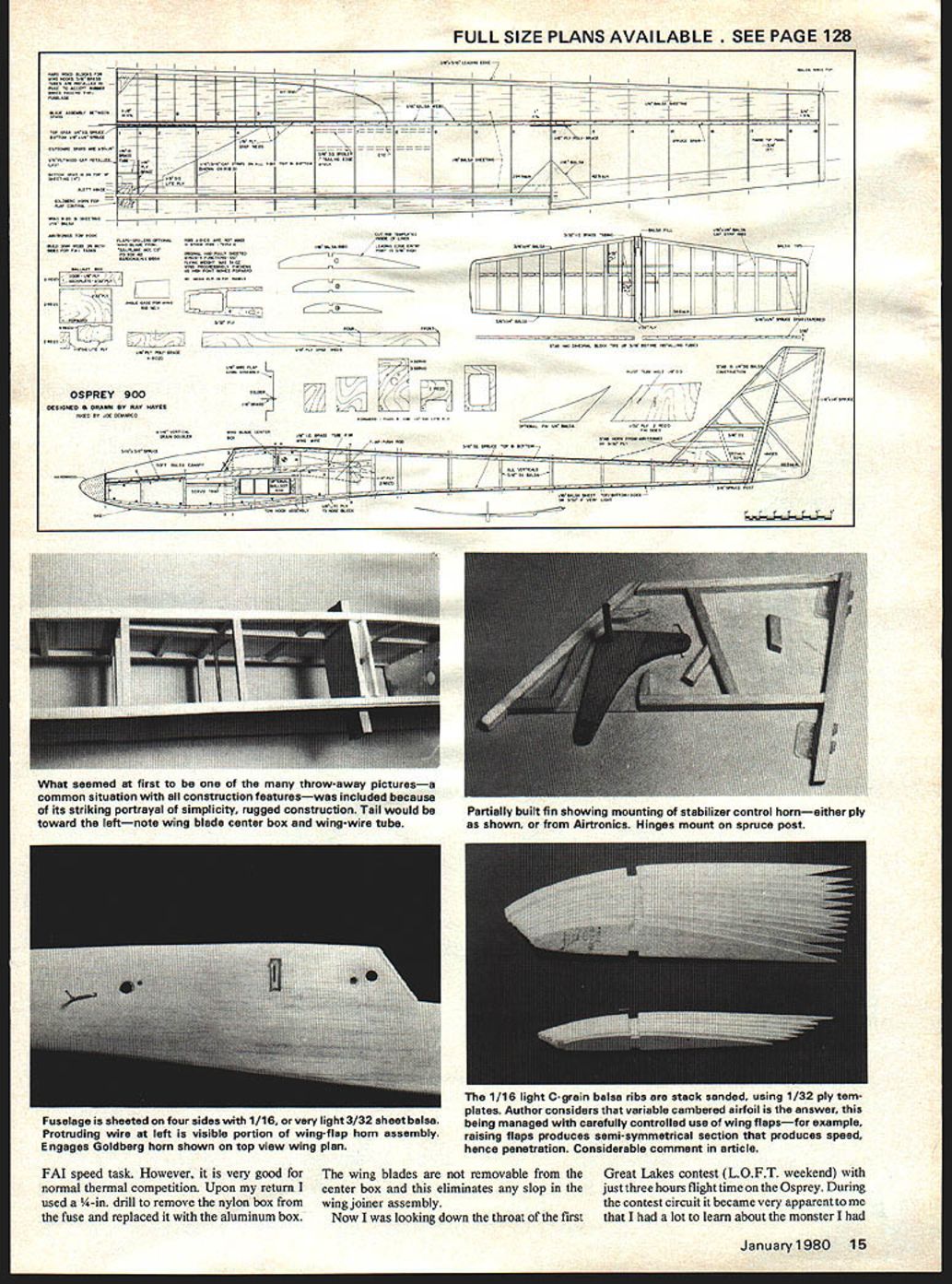
The wing blades are not removable from the center box and this eliminates any slop in the wing joiner assembly.
Now I was looking down the throat of the first Great Lakes contest (L.O.F.T. weekend) with just three hours flight time on the Osprey. During the contest circuit it became very apparent to me that I had a lot to learn about the monster I had created, particularly the amount of ballast to add under various conditions and where to use the flaps.
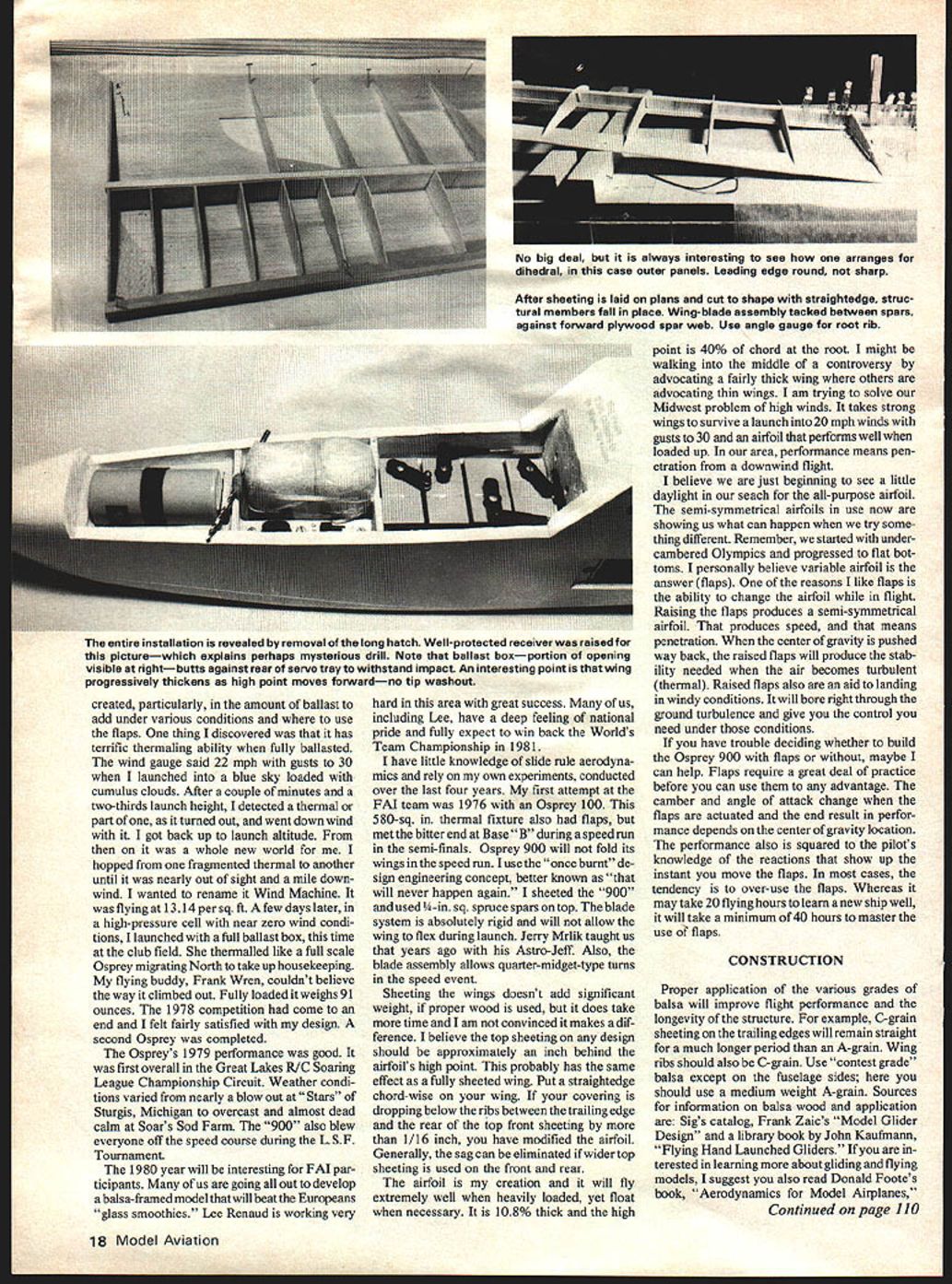
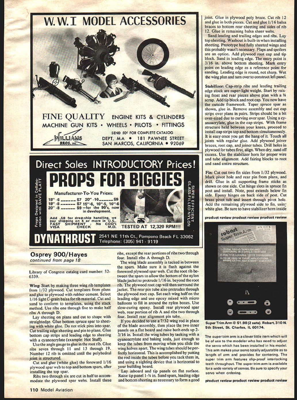
What seemed at first like throw-away pictures (a common situation when construction features are included) was used because of its striking portrayal of the simplicity and rugged construction.
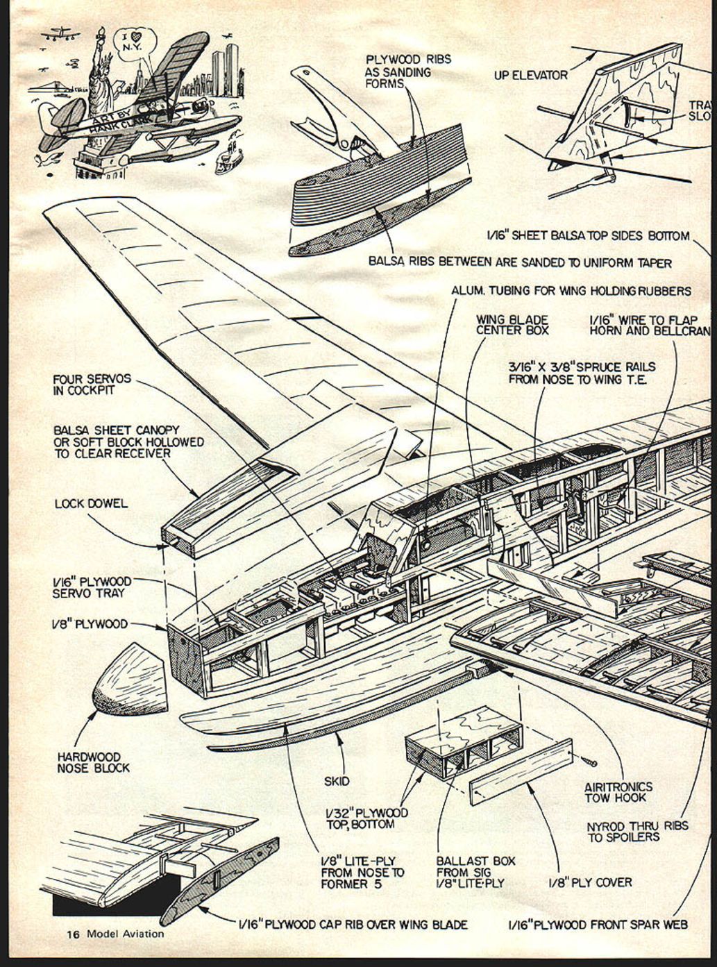
Materials and components
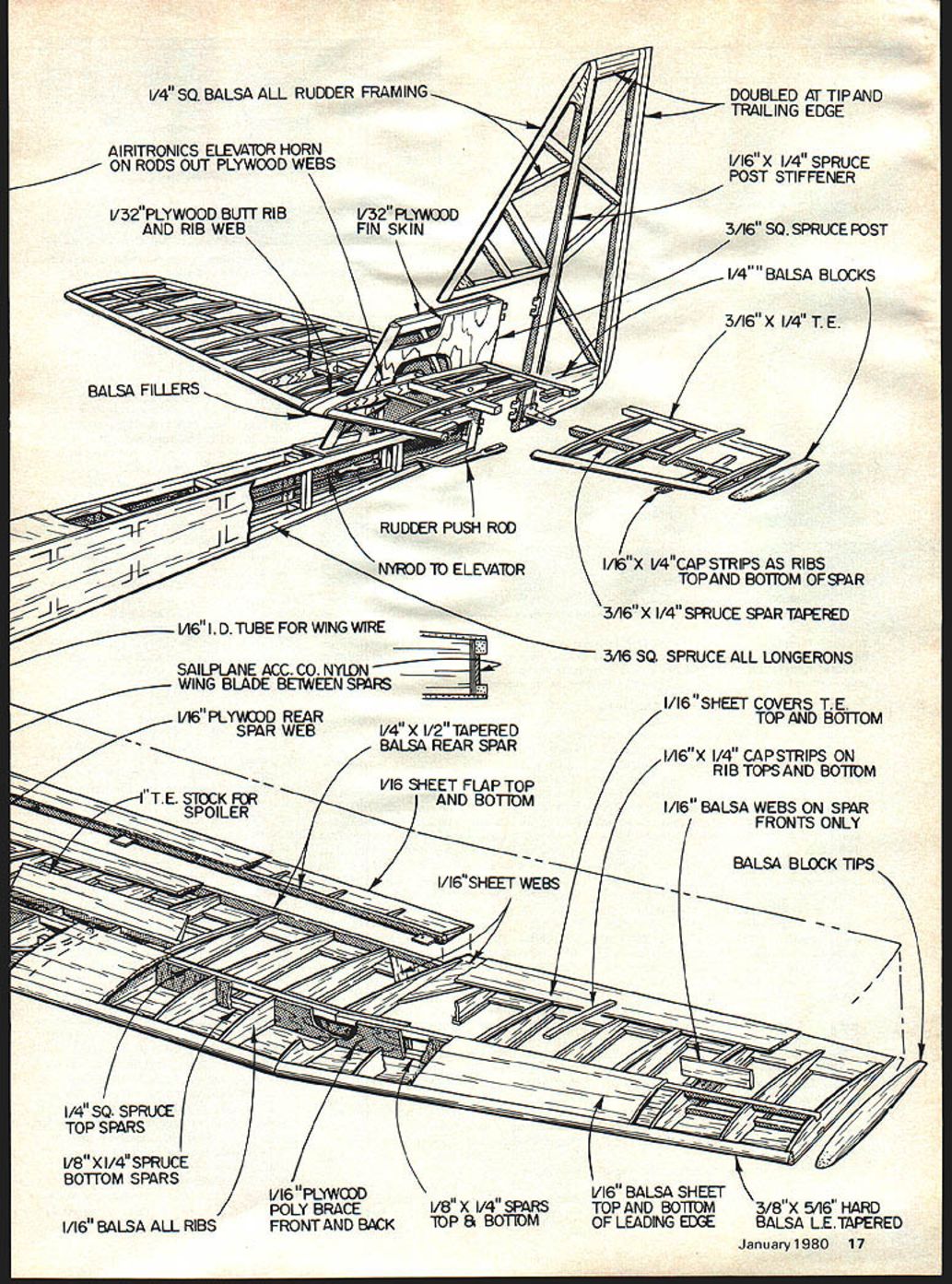
- 1/4" sq. balsa — all rudder framing
- Airtronics elevator horn on rods out plywood webs
- 1/32" plywood butt rib and rib web
- 1/32" plywood fin skin
- Balsa fillers
- Rudder push rod
- Nyrod to elevator
- 1/16" I.D. tube for wing wire
- Sailplane Acc. Co. nylon wing blade between spars
- 1/16" plywood rear spar web
- 1/4" x 1/2" tapered balsa rear spar
- 1/16" sheet flap top and bottom
- T.E. stock for spoiler
- 1/16" sheet webs
- 1/4" sq. spruce top spars
- 1/8" x 1/4" spruce bottom spars
- 1/16" balsa — all ribs
- 1/16" plywood poly brace front and back
- 1/8" x 1/4" spars top & bottom
- 1/16" balsa sheet top and bottom of leading edge
- 3/8" x 5/16" hard balsa L.E. tapered (doubled at tip and trailing edge)
- 1/16" x 1/4" spruce post stiffener
- 3/16" sq. spruce post
- 1/4" balsa blocks
- 3/16" x 1/4" T.E.
- 1/16" x 1/4" cap strips as ribs top and bottom of spar
- 3/16" x 1/4" spruce spar tapered
- 3/16" sq. spruce — all longerons
- 1/16" sheet covers T.E. top and bottom
- 1/16" x 1/4" capstrips on rib tops and bottom
- 1/16" balsa webs on spar fronts only
- Balsa block tips
- Aluminum tubing for wing holding rubbers
- 1/16" wire to flap
- Center box horn and bellcrank
I discovered that the Osprey has terrific thermalling ability when fully ballasted. The wind gauge said 22 mph with gusts to 30 when I launched into a blue sky loaded with cumulus clouds. After a couple of minutes and a two-thirds launch height, I detected a thermal — or part of one, as it turned out — and went downwind with it. I got back up to launch altitude. From then on it was a whole new world for me. I hopped from one fragmented thermal to another until it was nearly out of sight and a mile downwind. I wanted to rename it Wind Machine. It was flying at 13.14 ounces per sq. ft. A few days later, in a high-pressure cell with near zero wind conditions, I launched with a full ballast box, this time at the club field. She thermalled like a full-scale sailplane migrating north to take up housekeeping. My flying buddy, Frank Vren, couldn't believe the way it climbed out. Fully loaded it weighs 91 ounces. The 1978 competition had come to an end and I felt fairly satisfied with my design. A second Osprey was completed.
The Osprey's 1979 performance was good. It was first overall in the Great Lakes R/C Soaring League Championship Circuit. Weather conditions varied from nearly a blowout at "Stars" of Sturgis, Michigan to overcast and almost dead calm at Sears' Sod Farm. The "900" also blew everyone off the speed course during the L.S.F. Tournament.
The 1980 year will be interesting for FAI participants. Many of us are going all out to develop a balsa-framed model that will beat the Europeans' "glass smoothies." Lee Renaud is working very hard in this area with great success. Many of us, including Lee, have a deep feeling of national pride and fully expect to win back the World Team Championship in 1981.
I have little knowledge of slide-rule aerodynamics and rely on my own experiments, conducted over the last four years. My first attempt at the FAI team was 1976 with an Osprey 100. This 580-sq. in. thermal fixture also had flaps, but met the bitter end at Base "B" during a speed run in the semi-finals. Osprey 900 will not fold its wings in the speed run. I use the "once burnt" design engineering concept, better known as "that will never happen again." I sheeted the 900 and used 1/8-in. sq. spruce spars on top. The blade section is absolutely rigid and will not allow the wing to flex during launch. Jerry Mrlik taught us that years ago with his Astro-Jeff. Also, the blade assembly allows quarter-ridged-type turns in the speed event.
Sheeting the wings doesn't add significant weight, if proper wood is used, but it does take more time and I am not convinced it makes a difference. I believe the top sheeting on any design should be approximately an inch behind the airfoil's high point. This probably has the same effect as a fully sheeted wing. Put a straightedge chordwise on your wing. If your covering is dropping below the ribs between the trailing edge and the rear of the top front sheeting by more than 1/16 inch, you have modified the airfoil. Generally, the sag can be eliminated if wider top sheeting is used on the front and rear.
The airfoil is my creation and it will fly extremely well when heavily loaded, yet float when necessary. It is 10.8% thick and the high point is 40% of chord at the root. I might be walking into the middle of a controversy by advocating a fairly thick wing where others are advocating thin wings. I am trying to solve our Midwest problem of high winds. It takes strong wings to survive a launch into 20 mph winds with gusts to 30 and an airfoil that performs well when loaded up. In our area, performance means penetration from a downwind flight.
I believe we are just beginning to see a little daylight in our search for the all-purpose airfoil. The semi-symmetrical airfoils in use now are showing us what can happen when we try something different. Remember, we started with under-cambered Olympics and progressed to flat bottoms. I personally believe variable airfoil is the answer (flaps). One of the reasons I like flaps is the ability to change the airfoil while in flight. Raising the flaps produces a semi-symmetrical airfoil. That produces speed, and that means penetration. When the center of gravity is pushed way back, the raised flaps will produce the stability needed when the air becomes turbulent (thermal). Raised flaps also are an aid to landing in windy conditions. The model will bore right through the ground turbulence and give you the control you need under those conditions.
If you have trouble deciding whether to build the Osprey 900 with flaps or without, maybe I can help. Flaps require a great deal of practice before you can use them to any advantage. The camber and angle of attack change when the flaps are actuated and the end result in performance depends on the center of gravity location. The performance also is squared to the pilot's knowledge of the reactions that show up the instant you move the flaps. In most cases, the tendency is to over-use the flaps. Whereas it may take 20 flying hours to learn a new ship well, it will take a minimum of 40 hours to master the use of flaps.
CONSTRUCTION
Proper application of the various grades of balsa will improve flight performance and the longevity of the structure. For example, C-grain sheeting on the trailing edges will remain straight for a much longer period than A-grain. Wing ribs should also be C-grain. Use "contest grade" balsa except on the fuselage sides; here you should use a medium-weight A-grain. Sources for information on balsa wood and application are: Sig's catalog, Frank Zaic's Model Glider Design, and a library book by John Kaufmann, Flying Hand-Launched Gliders. If you are interested in learning more about gliding and flying models, I suggest you also read Donald Foote's book, Aerodynamics for Model Airplanes.
Library of Congress catalog card number: 52-6339.
Wing
- Start by making three wing rib templates from 1/32" plywood. Cut templates from plans and glue to plywood with rubber cement.
- Select 1/16" light C-grain balsa for rib material. Cut and sand to conform to templates, using the stack method. Use ribs one through five to make half ribs A through D.
- Lay bottom sheeting on plans and cut to shape with a straightedge. Glue bottom spruce spar to sheeting with white glue. Do not stick pins into spar.
- Cut trailing edge sheeting and pin to plans. Glue bottom cap strips and leading edge to sheeting with cyanoacrylate (example: Hot Stuff). Use an angle gauge to glue in the root rib. Glue ribs seven through 11 and 13 through 19. Number 12 rib is omitted until the polyhedral joint is constructed.
- Cut and glue (white glue) the forward 1/16" plywood spar web to top and bottom spars after installing the top spar. Ribs two through six are cut in half to accommodate the plywood spar webs. Install these ribs, except the rear portions of ribs two through four. Install ribs A through D.
- Tack the wing blade assembly between the spars. Make sure it is flush against the forward plywood spar web. Cut the root rib between the spars to allow the bottom of the nylon blade jacket to protrude 1/16" beyond the root rib. The plywood root cap will then surround the jacket. The rear pin tube also protrudes through the plywood root cap. Set each wing half on the leading edge and use epoxy mixed with microballoons to fill in around the nylon boxes. Use slow-curing epoxy. Install rear plywood spar web, rear portion of rib A, and ribs two through four. Install rear alignment pin tube.
- If you decide to use a 7/32" wing rod in place of the blade assembly, place the two inner panels on a flat board and raise both ends 3/16". Install the wing tubes by tacking with cyanoacrylate and baking soda — just enough to keep the tubes from moving when you slide the wing halves apart. The wing tubes should be perfectly horizontal; accomplish this by putting the rod inside the tubes before you tack them in and using a sighting device that is horizontal to your building board.
- Lay inboard and tip panels on a flat surface. Raise the tip panel 1-1/4". Sand spars, leading edge, and bottom sheeting as necessary to form a good joint. Glue in plywood poly brace. Cut rib 12 and glue in both pieces. Cut and glue 1/16" balsa braces to bottom rear sheeting and sides of rib 12. Glue in remaining balsa shear webs.
- Sand leading and trailing edges and ribs. Lay top sheeting. Washout is built-in when installing sheeting. The prototype had fully sheeted wings and this probably wasn't necessary. Flaps and spoilers are an option. Add plywood root cap and tip block. Sand in leading edge. The entry point is 3/16" above bottom sheeting — mark this on the leading edge as a reference for sanding. Leading edge is round, not sharp. Wet the wing plan and turn over to construct the left panel.
Stabilizer
- Cap-strip ribs and leading/trailing edge stock are super-lightweight. Start by raising front and rear pieces above the plan with a 1/8" scrap. Add tip block and root cap to form the outside framework.
- Taper the spruce spar as shown on plans and glue in. Remove the assembly and cut cap strips over plans in pairs; strips should be a bit oversized due to curving over the spar. Using cyanoacrylate, glue in the cap strips. With the frame structure held between your knees, install cap strips top and bottom simultaneously. Touch all joints with regular white glue.
- Add plywood joiner braces, root cap, and joiner tubes. Drill holes in plywood for tubes first, then align. When dry, sand off excess. Use the stabilizer horn for proper wire and tube alignment. Add fairing blocks to root and sand the entire structure.
Fin
- Cut out two fin sides from 1/32" plywood. Mark pivot hole and rear pin from plans and drill. Glue in all supporting frame sticks as shown on one side. Cut hinge slots in the spruce fin post and install; note the post extends below the fin side. Epoxy hinges on the back side of the post.
- Cut a brass pivot tube and insert through the pivot hole. Add the remaining plywood side to the fin, using white glue. Be sure to have the stabilizer horn inside the fin with the brass pivot tube running through it.
- Before the glue sets, install the stabilizer to the fin and, using a square, make sure the stabilizer is 90 degrees to the fin. Adjust the plywood fin side for proper alignment and use clothes pins to clamp the side to the fin assembly. Sand the leading edge round.
Fuselage
- Cut the fuse sides from plans and pin to two stacked 4" x 48" balsa sheets, 1/16" thick. Select wood carefully for constant grain, weight, and hardness. With the two sheets stacked, cut fuse sides using plans as guide. The fuse height at the wing shoulder is actually over four inches wide. Because the fuse corners are rounded, any shortage at the top will not be a problem.
- Cut opening for center wing blade box and drill hole for rear wing pin tube. Glue in all longerons, verticals, spruce rail and vertical 1/16" balsa doublers in the nose. Use the ballast box door as a guide when cutting the fuse side to install the ballast box. Cut out the ballast box from patterns. Use epoxy to install it in the fuse.
- Blind nuts are installed in Sig Lite ply on each side of the box after the ply is glued in. Do this by drilling holes in the ballast box door and spruce simultaneously, then epoxy the blind nuts from inside the fuse. Install wing-flap pushrod linkage and top and bottom sheeting.
- Cut an acceptance hole for an adjustable tow hook in the Sig Lite ply. Before gluing the bottom sheeting, add cross pieces for the blind nuts. Sand the canopy block and fuse. The original had two brass tubes through the fuse; the rubber bands that held the wings on passed through these tubes.
- Taper the top and bottom longerons starting four inches from the rear to zero thickness at the end of the fuse. Attach the pushrod to the bottom hole in the stab horn and cut an exit slot for the rudder pushrod. Install the flap horn through 1/16" plywood bearing plates if you are building flaps. Line up fuse sides and glue to the vertical tail post. Make sure the fin bottom touches the longerons. Add formers, nose block, rear alignment tube, and wing blade box. Use slow-curing epoxy on the wing box and tube to have plenty of time to accurately position the wing.
Covering
- Cover all surfaces with MonoKote.
- Add color-keyed tape to the underside of the fuselage in front to protect the covering from landing abrasions.
Flying
- Install radio equipment and balance the model on the spar for initial flights. C.G. can be set further back when you are ready. Keep the tow hook forward on the first flight. Remember, the wings will not flex on tow. Your first indication of too much line pressure will be veering left and right or a broken tow line.
- The first and second ballast boxes hold approximately one 1-ounce lead bar each; the third box holds 16 ounces. An 8-ounce bar is used in place of the 16-ounce bar in medium winds.
- I have performed outside loops, inverted pullouts from vertical dives, and barrel rolls with the 900. Have fun.
Transcribed from original scans by AI. Minor OCR errors may remain.

