
Over-EZBipe
Joe Johnson
Although flying models in circles with some sort of elevator control had been developed by Jim Walker, Victor Stanzel, and others prior to World War II, the concept really didn't catch on commercially until the post-war 1940s. Returning GIs, with their pockets full of separation pay and war bond savings, set off one of the most explosive eras of modeling ever seen. Numerous manufacturers rushed engines, kits, and hardware into production. Hobby shops sprung up everywhere, and CL models were being flown all over America.
By 1947 an incredible number of flying sites existed. Seemingly every hamlet and city sponsored a contest; they usually had CL circles and several very active clubs. One must remember that this was the era of spark-ignition engines, such as the Super Cyclone, Arden, Ohlsson, Vivel, Cannon, McCoy, Rocket, O.K., Pacemaker, Fleetwind, Madewell—and, yes, Rogers, Thor, Genie, and G.H.Q. Needless to say, the CL models of the time were of necessity much different than modern designs.
Those available kits were generally of relatively small size, heavy construction, and rather limited maneuverability. A quick check of advertisers in a magazine of that period lists such CL kits as Super Zilch, Topping (all metal), Fireball, Super V, Shark, Dreamer, VeeGee, Cyclone, and the Rookie Trainer. That is just a quick glance, since there were at least 100 manufacturers producing kits of varying completeness.
Most of us who were flying CL models eventually became bored with flying around in circles with only an occasional loop. Even the first CL model had taken some doing; the air was literally on the end of a set of lines he was holding! To successfully run a spark engine consistently was a challenge in itself, and those problems discouraged many potential fliers repeatedly. Little wonder, then, that the Drone Diesel and several imported compression-ignition engines were attracting much attention.
At the Olathe Nationals in August 1947, something revolutionary took place. Ray Arden displayed his adaptation of the "hot plug" principle to model aircraft power plants. This rather eccentric genius had revolutionized model flying. We will forever treasure the moments spent at the U.S. Naval Air Station observing this man run engines without coil, condenser, points, or any onboard battery. Awestruck is the word.
Suddenly, models of all kinds could be made lighter, narrower, and less complex. More importantly, the engines would start and run with minimal hassle. Sadly, many of the engines we respected when run on spark would nearly self-destruct on glow. This led to the rather rapid decline and eventual closing of several major firms. Nonetheless, the glow plug most certainly set off the second boom in CL flying. We could build models lightly enough, and depend on good performance from our power plants, for aerobatics to be possible.
Jim Saftig, Davy Slagle, Mad Man Yates, Bob Tucker, and others (with their outside loops, inverted flights, eights, and such) became our gurus. We all hung glow engines on our thin-airfoiled overweight models and attempted to emulate our heroes. Inverted flight looked relatively easy when someone else was doing it, but (oh my!) many models were splattered when trying it. All our senses rebelled at pulling down control to keep from diving.
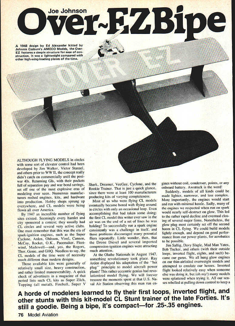
A horde of modelers learned to fly their first loops, inverted flights, and other stunts with a kit-model CL Stunt trainer of the late Forties. It's still a goodie. Being a bipe, it's compact—for .25–.35 engines.
A number of modelers learned inverted flight the hard way. One manufacturer even marketed a handle that was pivoted so that, when the model was inverted, a lever could be released and the up-line became the down-line. We had one, but can't say that it solved the problem.
Into this scene of model carnage Johnny Casburn's AMECO Models introduced what he described as "an inverted trainer." Aptly named Overeasy in the advertisements and OverEZ on the drawings, this bipe caught this writer's attention when an advertisement in the December 1947 Air Trails showed a photo of Johnny flying one inverted.
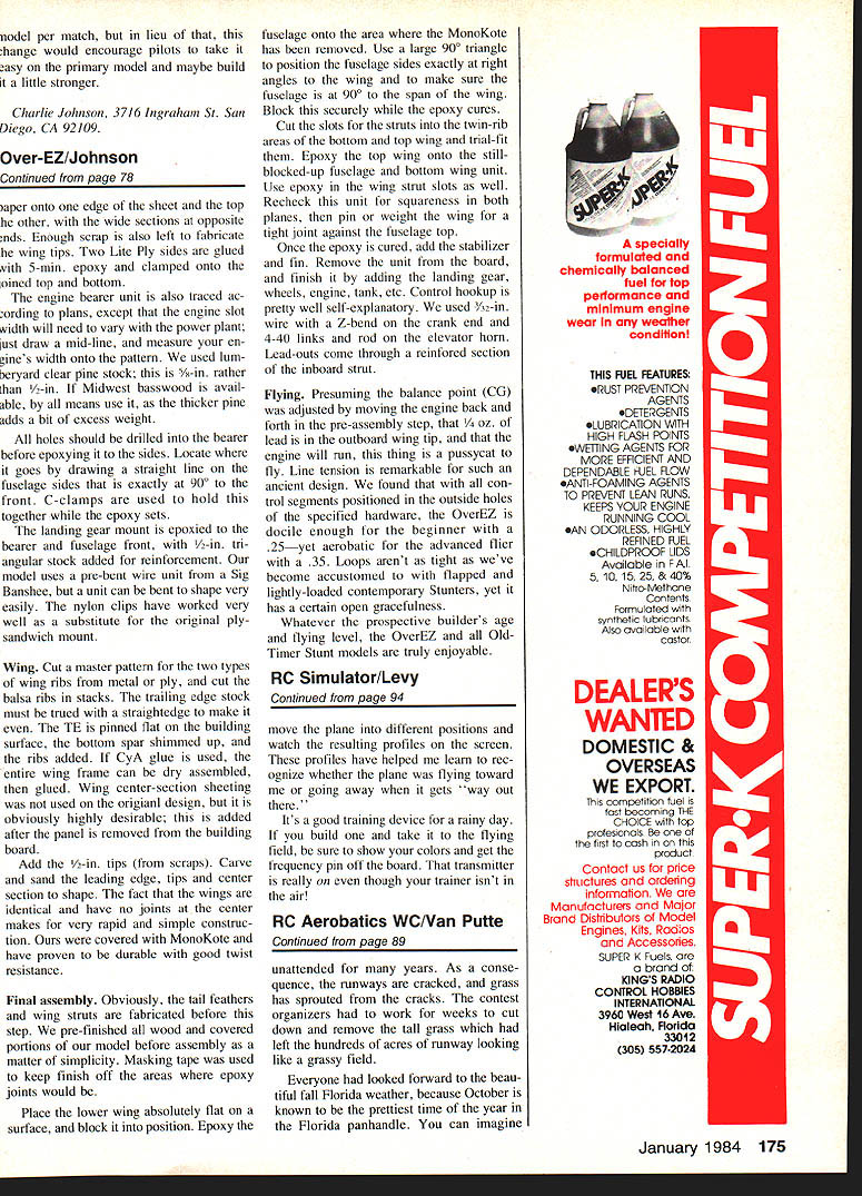
It was a revolutionary design in its day because it featured a profile fuselage and yet was a bipe. Designer Ed Alexander (who to this day operates a hobby shop in Fort Worth) had cleverly combined the simplicity of an all-sheet fuselage with a solid horizontal mount for the engine and bellcrank. He used wing struts to further reinforce the wing attachment. Incredibly simple construction by 1947 standards made the OverEZ a very attractive choice to a teenage boy who figured that, at least, it would be simple to build another model after the inevitable crashes.
Memory grows a bit dim, but we think our OverEZs were powered with O&R .29 "side splitters"—so called in reference to the tendency for the crankcase to split when the engine was run on glow. The wings were covered with G.M. silkspan, the solid wood areas with Testors STA, and the colors were silver and red. We can definitely recall our first-ever outside loop with the OverEZ and some very jumpy inverted laps. But we did get the foolish thing inverted and upright in the same flight.
Just in passing, we should also mention that the introduction of stranded-cable flying lines was about the same time as Ray Arden's glow plug. Before that we used (and I do mean used) single-strand lines. Imagine a 15-year-old kid with no adult help trying to reel up 70 ft. of single-strand line on a homemade reel. We thought the first Jim Walker U-Reely self-contained handle and lines was the greatest thing since sliced bread.
OK, so what does this little glimpse of flying Control Line in 1945–1947 have to do with anything? Mostly this: we recently built and flew some of Johnny Casburn's contemporary RC kits, and we were very impressed. This led to several phone conversations with Johnny and an inevitable inquiry if he happened to have a set of drawings for the OverEZ. He didn't, but our rekindled interest led us to continue looking.
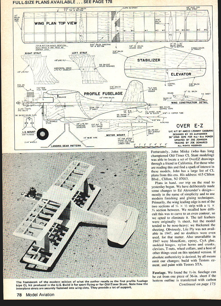
Fortunately, John Miske (who has long championed Old-Timer CL Stunt modeling) was able to locate a set of OverEZ drawings through a friend in California. For those who are reading this and find a spark of interest in these models, John has a large list of CL plans from this era. His address: 415 Clifton Blvd., Clifton, NJ 07013.
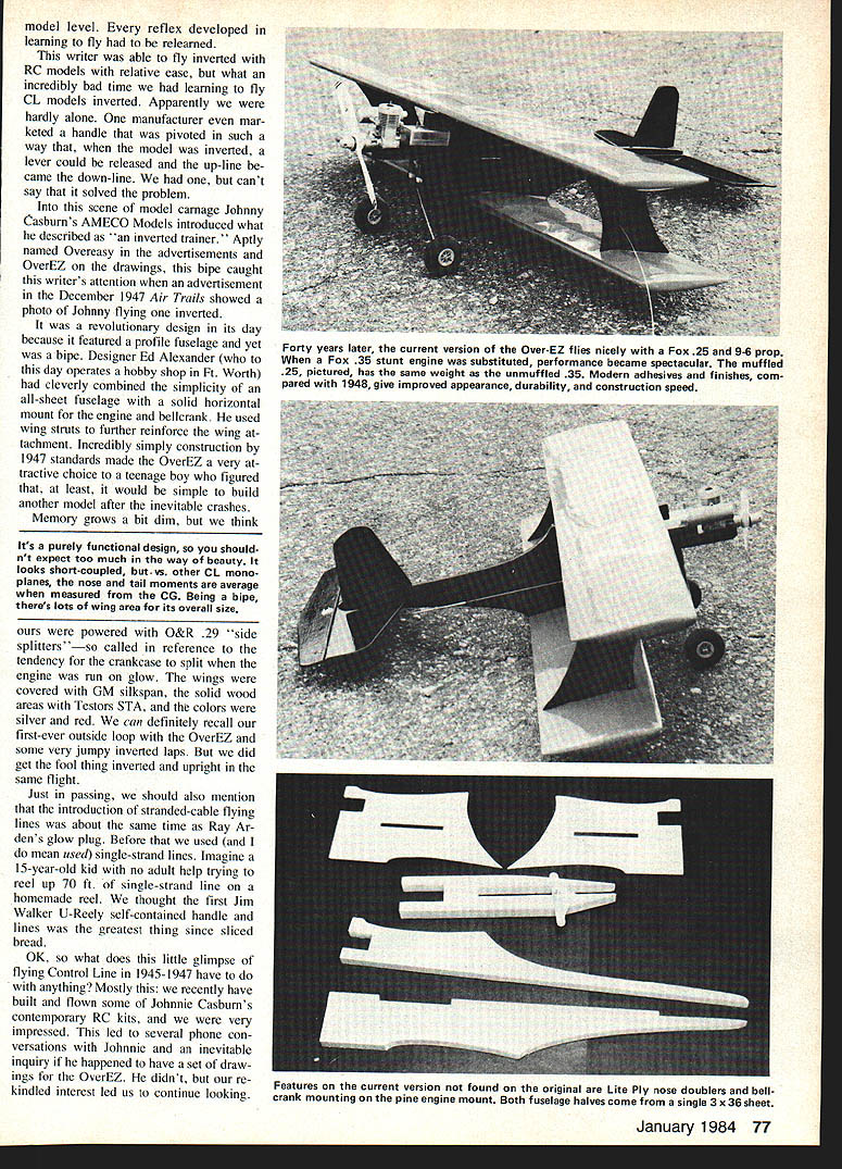
Plans in hand, our trip on the road to yesterday began. We have deliberately made some changes to Ed Alexander's design—mostly in the name of simplicity and to use modern finishing and gluing techniques. Primarily, the wing leading edge is not of the two sections of 1/8 x 1/2 strip with a 1/4 x 1/4 section between. We recalled how difficult this was to carve to an even contour, so we opted to eliminate it. The tail feathers were originally 1/8 sheet, but the model tended to be nose-heavy; we thickened the sheeting. Obviously, Lite Ply was not available in 1947, and no doublers were even used, for that matter. Also unavailable in 1947 were MonoKote, epoxy, CA glue, molded hinges, nylon horns and cranks, clevises, T-nuts, wheel collars, and a host of other things used on this updated version. If absolute authenticity is desired, by all means omit our changes; build with Testors cement, and paint with Testors STA.
Fuselage
We found the 1/8-in. fuselage can be cut from one piece of 3/16-in. sheet if the bottom outline is transferred with carbon paper onto one edge of the sheet and the top to the other, with the wide sections at opposite ends. Enough scrap is also left to fabricate the wing tips. Two Lite Ply sides are glued with 5-min. epoxy and clamped onto the pointed top and bottom.
The engine bearer unit is also traced according to plans, except that the engine slot width will need to vary with the power plant; just draw a mid-line and measure your engine's width onto the pattern. We used lumberyard clear pine stock; this is 5/8-in. rather than 1/2-in. If Midwest basswood is available, by all means use it, as the thicker pine adds a bit of excess weight.
All holes should be drilled into the bearer before epoxying it to the sides. Locate where it goes by drawing a straight line on the fuselage sides that is exactly at 90° to the front. C-clamps are used to hold this together while the epoxy sets.
The landing gear mount is epoxied to the bearer and fuselage front, with 1/2-in. triangular stock added for reinforcement. Our model uses a pre-bent wire unit from a Sig Banshee, but a unit can be bent to shape very easily. The nylon clips have worked very well as a substitute for the original plywood sandwich mount.
Wing
Cut a master pattern for the two types of wing ribs from metal or ply, and cut the balsa ribs in stacks. The trailing edge stock must be trued with a straightedge to make it even. The TE is pinned flat on the building surface, the bottom spar shimmed up, and the ribs added. If CA glue is used, the entire wing frame can be dry assembled, then glued. Wing center-section sheeting was not used on the original design, but it is obviously highly desirable; this is added after the panel is removed from the building board.
Add the 1/2-in. tips (from scraps). Carve and sand the leading edge, tips and center section to shape. The fact that the wings are identical and have no joints at the center makes for very rapid and simple construction. Ours were covered with MonoKote and have proven to be durable with good twist resistance.
Final assembly
Obviously, the tail feathers and wing struts are fabricated before this step. We pre-finished all wood and covered portions of our model before assembly as a matter of simplicity. Masking tape was used to keep finish off the areas where epoxy joints would be.
Place the lower wing absolutely flat on a surface, and block it into position. Epoxy the fuselage onto the area where the MonoKote has been removed. Use a large 90° triangle to position the fuselage sides exactly at right angles to the wing and to make sure the fuselage is at 90° to the span of the wing. Block this securely while the epoxy cures.
Cut the slots for the struts into the twin-rib areas of the bottom and top wing and trial-fit them. Epoxy the top wing onto the still-blocked-up fuselage and bottom wing unit. Use epoxy in the wing strut slots as well. Recheck this unit for squareness in both planes, then pin or weight the wing for a tight joint against the fuselage top.
Once the epoxy is cured, add the stabilizer and fin. Remove the unit from the board, and finish it by adding the landing gear, wheels, engine, tank, etc. Control hookup is pretty well self-explanatory. We used 3/32-in. wire with a Z-bend on the crank end and 4-40 links and rod on the elevator horn. Lead-outs come through a reinforced section of the inboard strut.
Flying
Presuming the balance point (CG) was adjusted by moving the engine back and forth in the pre-assembly step, that 1/4 oz. of lead is in the outboard wing tip, and that the engine will run, this thing is a pussycat to fly. Line tension is remarkable for such an ancient design. We found that with all control segments positioned in the outside holes of the specified hardware, the OverEZ is docile enough for the beginner with a .25—yet aerobatic for the advanced flier with a .35. Loops aren't as tight as we've become accustomed to with flapped and highly-loaded contemporary Stunters, yet it has a certain open gracefulness.
Whatever the prospective builder's age and flying level, the OverEZ and all Old-Timer Stunt models are truly enjoyable.
Transcribed from original scans by AI. Minor OCR errors may remain.

