
The P-3
WHAT IS A P-3? Simply speaking, it is Pastor's third design. Not a very imaginative name, but when someone asks you what it is, you won't get tongue-tied trying to say "P-3."
The P-3 was designed as a logical progression from the 1/2A pattern ship. I don't normally agree with the Detroit syndrome that bigger is better. However, in this case, the advantages justify the changes. The power-to-weight ratio is better, and the flight will not be a disaster if the engine is not running perfectly. There is plenty of room for a third servo for rudder control. This means that there are very few maneuvers that can't be done. Knife-edge flight, stall turns, four-point rolls, and slow rolls are all within the capabilities of this ship.
For all of you who have larger radios, there is still plenty of room for two channels. Now you too can get out there and show up all of those 1/2A pattern fliers.
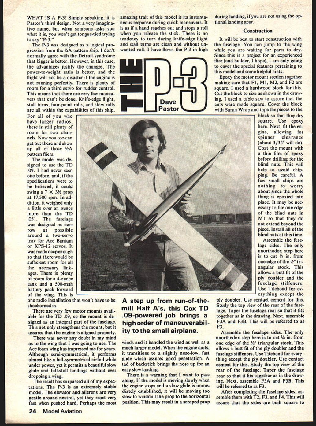
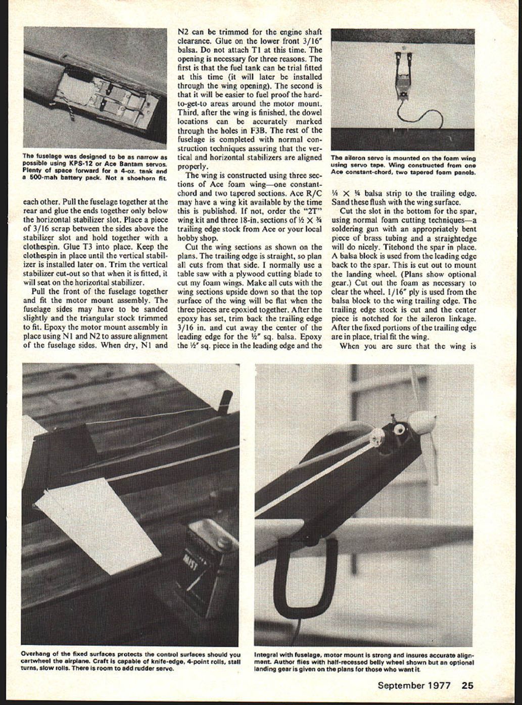
The model was designed to use the TD .09. I had never seen one before, and, if the specifications were to be believed, it could swing a 7 x 3-1/2 prop at 17,500 rpm. In addition, it weighed only a little over an ounce more than the TD .051. The fuselage was designed as narrow as possible around a two-servo tray for Ace Bantam or KPS-12 servos. It was made deep enough so that there would be sufficient room for all the necessary linkages. There is plenty of room for a 4-ounce tank and a 500-mah battery pack forward of the wing. This is one radio installation that won't have to be shoehorned in.
There are very few motor mounts available for the TD .09, so the mount is designed as an integral part of the fuselage. This not only strengthens the mount, but it assures that the engine is aligned properly.
There was never any doubt in my mind as to the wing that I was going to use. The Ace foam wing has impressed me for years. Although semi-symmetrical, it performs almost like a full-symmetrical airfoil under power, yet it permits a beautiful slow glide and full-stall landings without ever dropping a wing.
The result has surpassed all of my expectations. The P-3 is an extremely stable model. The elevator and ailerons are very gentle around neutral, yet they react very fast when pushed hard. Perhaps the most amazing trait of this model is its instantaneous response during quick maneuvers. It is as if a hand reaches out and stops a roll when you release the stick. There is no tendency to turn during knife-edge flight and stall turns are clean and without unwanted roll. I have flown the P-3 in high winds and it handled the wind as well as a much larger model. When the engine quits, it transitions to a slightly nose-low, fast glide which assures good penetration. A tad of backstick brings the nose up for an easy slow landing.
There is a warning that I want to pass along. If the model is moving slowly when the engine stops and a slow glide is immediately established, it will be moving too slow to windmill the prop to the horizontal position. This may result in a scraped prop during landing, if you are not using the optional landing gear.
Construction
It will be best to start construction with the fuselage. You can jump to the wing while you are waiting for parts to dry. Since this is a project for an experienced flier (and builder, I hope), I am only going to cover the special features pertaining to this model and some helpful hints.
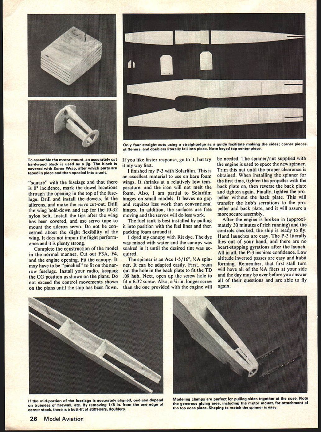
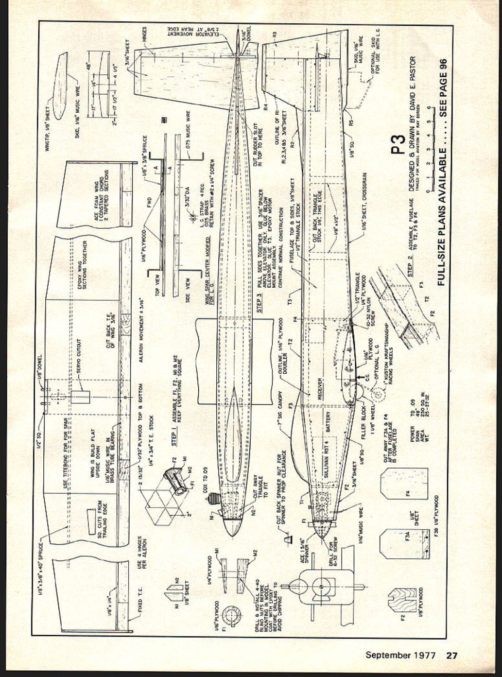
Epoxy the motor mount section together making sure that F1, M1, M2, and F2 are square. I used a hardwood block for this. Cut the block to size as shown in the drawing. I used a table saw to assure that the cuts were made square. Cover the block with Saran Wrap and tape the pieces to the block so that they dry square. Use epoxy here. Next, fit the engine, allowing for spinner clearance (about 3/32" will do). Coat the mount with a thin film of epoxy before drilling for the blind nuts. This will help to avoid chipping. Be careful. A few small chips are nothing to worry about since the whole thing is epoxied into place. It may be necessary to file one edge of the blind nuts in M1 so that they do not extend beyond the piece. Install all of the blind nuts at this time.
Assemble the fuselage sides. The only unorthodox step here is to cut 1/8 in. from one edge of the 1/8" triangular stock. This allows a butt fit of the ply doubler and the fuselage stiffeners. Use Titebond for everything except the ply doubler. Use contact cement for this. Study the top view of the rear of the fuselage. Taper the fuselage rear so that it fits together as in the drawing. Next, assemble F3A and F3B. This will be referred to as F3.
After completing the fuselage sides, assemble them with T2, F3, and F4. This will assure that the sides are built square. Pull the fuselage together at the rear and glue the ends together only below the horizontal stabilizer slot. Place a piece of 3/16 scrap between the sides above the stabilizer slot and hold together with a clothespin. Glue T3 into place. Keep the clothespin in place until the vertical stabilizer is installed later on. Trim the vertical stabilizer cut-out so that when it is fitted, it will seat on the horizontal stabilizer.
Pull the front of the fuselage together and fit the motor mount assembly. The fuselage sides may have to be sanded slightly and the triangular stock trimmed to fit. Epoxy the motor mount assembly in place using N1 and N2 to assure alignment of the fuselage sides. When dry, N1 and N2 can be trimmed for the engine shaft clearance. Glue on the lower front 3/16" balsa. Do not attach T1 at this time. The opening is necessary for three reasons. The first is that the fuel tank can be trial fitted at this time (it will later be installed through the wing opening). The second is that it will be easier to fuel-proof the hard-to-get-to areas around the motor mount. Third, after the wing is finished, the dowel locations can be accurately marked through the holes in F3B. The rest of the fuselage is completed with normal construction techniques assuring that the vertical and horizontal stabilizers are aligned properly.
The wing is constructed using three sections of Ace foam wing—one constant-chord and two tapered sections. Ace R/C may have a wing kit available by the time this is published. If not, order the "2T" wing kit and three 18-in. sections of 1/2 x 3/4 trailing edge stock from Ace or your local hobby shop.
Cut the wing sections as shown on the plans. The trailing edge is straight, so plan all cuts from that side. I normally use a table saw with a plywood cutting blade to cut my foam wings. Make all cuts with the wing sections upside down so that the top surface of the wing will be flat when the three pieces are epoxied together. After the epoxy has set, trim back the trailing edge 3/16 in. and cut away the center of the leading edge for the 1/2" sq. balsa. Epoxy the 1/2" sq. piece in the leading edge and the 1/4 x 1/4 balsa strip to the trailing edge. Sand these flush with the wing surface.
Cut the slot in the bottom for the spar, using normal foam cutting techniques—a soldering gun with an appropriately bent piece of brass tubing and a straightedge will do nicely. Titebond the spar in place. A balsa block is used from the leading edge back to the spar. This is cut out to mount the landing wheel. (Plans show optional gear.) Cut out the foam as necessary to clear the wheel. 1/16" ply is used from the balsa block to the wing trailing edge. The trailing edge stock is cut and the center piece is notched for the aileron linkage. After the fixed portions of the trailing edge are in place, trial fit the wing.
When you are sure that the wing is "square" with the fuselage and that there is 0° incidence, mark the dowel locations through the opening in the top of the fuselage. Drill and install the dowels, fit the ailerons, and make the servo cut-out. Drill the wing hold-down and tap for the 10-32 nylon bolt. Install the tips after the wing has been covered, and use servo tape to mount the aileron servo. Do not be concerned about the slight flexibility of the wing. It does not impair the flight performance and it is plenty strong.
Complete the construction of the model in the normal manner. Cut out F3A, F4, and the engine opening. Fit the canopy. It may have to be "pinched" to fit on the narrow fuselage. Install your radio, keeping the CG position as shown on the plans. Do not exceed the control movements shown on the plans until the ship has been flown.
If you like faster response, go to it, but try it my way first.
I finished my P-3 with Solarfilm. This is an excellent material to use on bare foam wings. It shrinks at a relatively low temperature, and the iron will not melt the foam. Also, I am partial to Solarfilm hinges on small models. It leaves no gap and requires less work than conventional hinges. In addition, the surfaces are free moving and the servos will do less work.
The fuel tank is best installed by pulling it into position with the fuel lines and then packing foam around it.
I dyed my canopy with Rit dye. The dye was mixed with water and the canopy was soaked in it until the desired tint was acquired.
The spinner is an Ace 1-5/16", 1/2A spinner. It can be adapted easily. First, ream out the hole in the back plate to fit the TD .09 hub. Next, open up the screw hole to fit a 6-32 screw. Also, a 1/4-in. longer screw than the one provided with the engine will be needed. The spinner/nut supplied with the engine is used to space the new spinner. Trim this nut until the proper clearance is obtained. When installing the spinner for the first time, tighten the propeller with the back plate on, then reverse the back plate and tighten again. Finally, tighten the propeller without the back plate. This will transfer the hub's serrations to the propeller and back plate, and it will assure a more secure assembly.
After the engine is broken in (approximately 30 minutes of rich running) and the controls checked, the ship is ready to fly. Hand launches are easy. The P-3 literally flies out of your hand, and there are no heart-stopping gyrations after the launch. All in all, the P-3 inspires confidence. Low altitude inverted passes are easy and habit forming. Remember, that first stall turn will have all of the 1/2A fliers at your side and the day may be over before you answer all of their questions and are able to fly again.
WHAT IS P-3
Simply speaking, P-3 is Pastor's third design. A very imaginative name — when someone asks 'what?' you won't get tongue-tied trying to say 'P-3.' P-3 is designed as a logical progression from a 1/2A pattern ship. I don't normally agree with the Detroit syndrome — bigger is better. However, in this case the advantages justify the changes. Power-to-weight ratio is better. Flight will be more forgiving if the engine is not perfect. There is plenty of room for a third servo; rudder control means very few maneuvers can't be done. Knife-edge flight, stall turns, four-point rolls and slow rolls are within the ship's capabilities. The ship can have larger radios and still plenty of room for two channels.
Now, too, you can get out, show up pattern fliers. The model was designed to use a TD .09 never seen before; specifications believed could swing a 7 x 3 prop at 17,500 rpm. In addition, it weighed little over an ounce more than a TD .051 fuselage designed narrow, possible around a two-servo tray. Ace Bantam/KPS-12 servos are made deep enough to provide sufficient room for the necessary linkages. There is plenty of room for a 4-ounce tank and a 500-mAh battery pack forward. Wing and radio installation won't have to be shoehorned. Very few motor mounts are available; the TD .09 mount is designed as an integral part of the fuselage. This strengthens the mount and assures the engine is aligned properly — never doubt which way the wing is going to use.
The Ace foam wing has impressed for years. Although semi-symmetrical, it performs almost like a full-symmetrical airfoil under power, yet permits a beautiful slow glide and full-stall landings without ever dropping a wing. The result has surpassed expectations. P-3 is an extremely stable model. The elevator and ailerons are very gentle around neutral, yet react very fast when pushed hard.
Perhaps the most amazing trait of the model is its instantaneous response during quick maneuvers. The hand reaches out, stops a roll, releases the stick — there is no tendency to turn during knife-edge flight. Stall turns are clean with no unwanted roll. I have flown P-3 at high U. II. Dave Fl1 Pastor stepped up from a run-of-the-mill Half A. The Cox TD .09-powered job brings a high order of maneuverability in a small airplane. Winds are handled well; compared with much larger models, when the engine quits it transitions slightly nose-low. The fast glide assures good penetration; a tad of back-stick brings the nose up for an easy, slow landing.
One warning I want to pass along: if the model is moving slowly when the engine stops, a slow glide is immediately established. If it is moving too slowly and the prop is windmilling in a horizontal position, the prop may be scraped during landing if using the optional landing gear.
Construction will best start with the fuselage. You can jump the wing while waiting for parts to dry. Since the project assumes an experienced flier/builder, I hope I am going to cover special features pertaining to the model and offer some helpful hints.
Epoxy the motor-mount section together, making sure F1, M1, M2, F2 are square. Use a hardwood block. Cut the block size shown on the drawing using a table saw; assure the cuts are made square. Cover the block with Saran Wrap and tape the pieces to the block while drying to keep them square. Use epoxy.
Next, fit the engine allowing spinner clearance of about 3/32 in. Coat the mount with a thin film of epoxy before drilling. Installing blind nuts will help avoid chipping; be careful — a few small chips are nothing to worry about since the whole thing is epoxied in place. It may be necessary to file the edge if blind nuts M1 extend beyond the piece. Install the blind nuts at this time.
Assemble fuseage [fuselage] sides. An unorthodox step-cut of the triangular stock allows butt-fitting the ply doubler and fuselage stiffeners. Use Titebond for everything except the ply doubler — use contact cement for the ply doubler. Study the top view; the rear fuselage taper fits together as shown on the drawing.
Next assemble F3A and F3B (will be referred to as F3). After completing the fuselage sides, assemble T2, F3 and F4 to assure the sides are built square.
Pull the fuselage together at the rear. Glue the ends together below the horizontal stabilizer slot. Place a 3/16-in. scrap piece between the sides above the stabilizer slot to hold them together with a clothespin. Glue T3 in place. Keep the clothespin in place until the vertical stabilizer is installed later. Trim the vertical stabilizer cut-out so the fitted stabilizer will seat the horizontal stabilizer.
Pull the front fuselage together and fit the motor-mount assembly. The fuselage sides may have to be sanded slightly where the triangular stock was trimmed.
Transcribed from original scans by AI. Minor OCR errors may remain.

