
P-38
IN THE OPINION of many, the Lockheed P-38 Lightning was the best fighter aircraft of World War II. I might be willing to concede that the P-51 was the best in the second half of the war, but the P-38 was operational much earlier and still very much in the thick of it at the end.
Just how good was the P-38? After a long over-water flight, it intercepted an aircraft carrying Admiral Yamamoto (planner of the Pearl Harbor attack), shot it down, and returned. Richard "Dick" Bong was (and still is) America's top ace with 40 victories while primarily flying P-38s. Thomas B. McGuire, Jr., America's No. 2 ace with 38 victories, also flew P-38s. Vividly showing its toughness, in no other fighter I know of could Lt. Thomas W. Smith have rammed an Me 109 head-on deep over Germany, and still returned to his home base in England.
With four .50-cal. machine guns plus a 20 mm cannon, all concentrated in the nose, the P-38 earned the German nickname Gabelschwanz Teufel — "Fork-Tailed Devil." Oberleutnant Franz Stigler, a 28-victory ace for Germany, once stated: "One cardinal rule we never forgot was to avoid fighting a P-38 head on. That was suicide." Their armament was so heavy and their firepower so murderous that no one ever tried that type of attack more than once.
Of course, our model isn't that tough, but the way I fly at times, it ought to be in order to survive.
Model overview
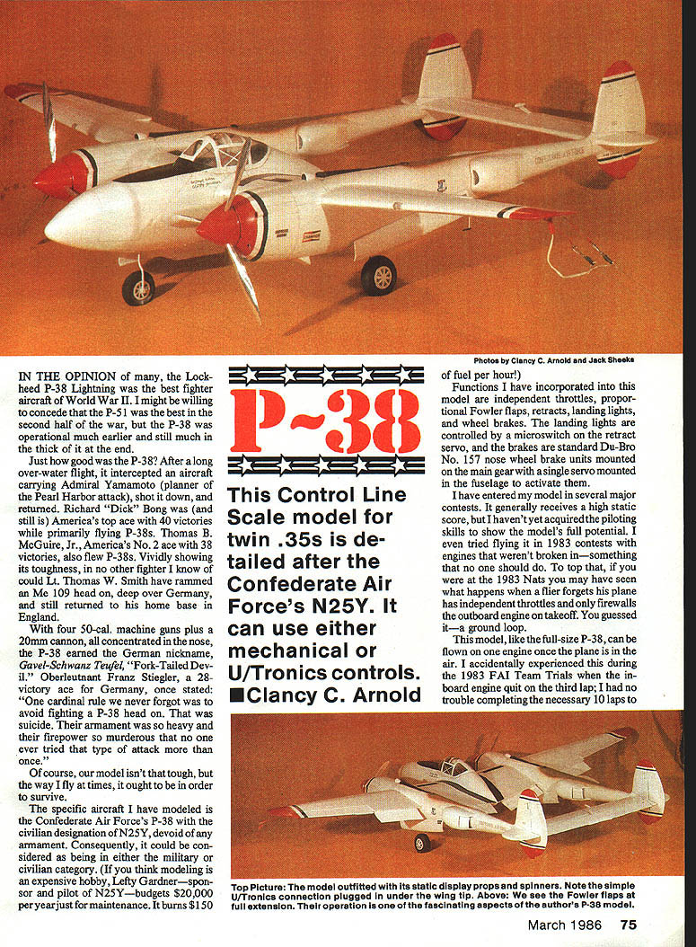
The specific aircraft I have modeled is the Confederate Air Force's P-38 with the civilian registration N25Y, devoid of any armament. Consequently, it could be considered as being in either the military or civilian category. (If you think modeling is an expensive hobby, Lefty Gardner — sponsor and pilot of N25Y — budgets $20,000 per year just for maintenance. It burns about $150 per hour for fuel.)
This control-line scale model for twin .35 engines is detailed after the Confederate Air Force's N25Y. It can use either mechanical or U/Tronics controls. — Clancy C. Arnold
Features and functions
I have incorporated the following into this model:
- Independent throttles.
- Proportional Fowler flaps.
- Retracts.
- Landing lights (controlled by a microswitch on the retract servo).
- Wheel brakes (standard Du-Bro No. 157 nose wheel brake units mounted on the main gear, with a single servo mounted in the fuselage to activate them).
Bellcranks and hardware:
- Elevator bellcrank mount is epoxied through the spar and to the leading edge. CL Scale models are subjected to a high pull test for safety (at 10 1/4 lb., my P-38 must withstand a 65-lb pull test). X-Cell and Sig nylon bellcranks have worked well for me.
- Flap bellcranks are made from .062 aluminum sheet, using Du-Bro No. 121 E-Z Connectors, .055 music wire pushrods, and solder lugs for connecting flap runs to the flap servo.
Contest history and handling
I have entered this model in several major contests; it generally receives a high static score. I haven't yet acquired the piloting skills to show the model's full potential. I tried flying it in 1983 contests with engines that weren't broken in — something no one should do. At the 1983 Nats you may have seen what happens when a flier forgets his plane has independent throttles and only firewalls the outboard engine on takeoff — you guessed it: a ground loop.
This model, like the full-size P-38, can be flown on one engine once the plane is in the air. I accidentally experienced this during the 1983 FAI Team Trials when the inboard engine quit on the third lap; I had no trouble completing the necessary 10 laps to qualify the flight. Clarence "Kelly" Johnson, designer of the P-38, knew what he was doing when he placed a rudder in line with each engine when laying out the basic design in 1937.
Engines and performance
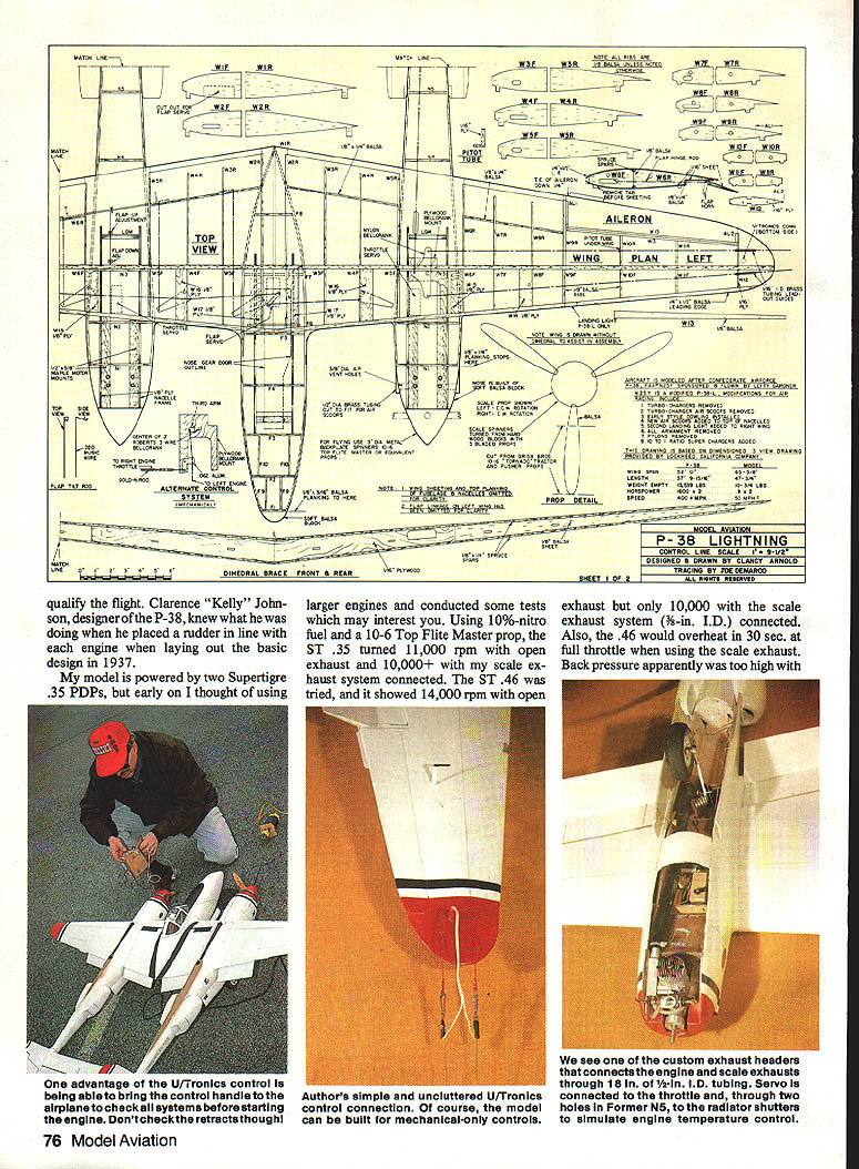
My model is powered by two Super Tigre .35 PDPs. Early on I experimented with larger engines and conducted tests which may interest you:
- With 10%-nitro fuel and a 10x6 Top Flite Master prop:
- ST .35 turned about 11,000 rpm with open exhaust and 10,000+ rpm with my scale exhaust system connected.
- ST .46 showed 14,000 rpm with open exhaust but only about 10,000 rpm with the scale exhaust system (3/8-in. I.D.) connected. The .46 would overheat in 30 seconds at full throttle when using the scale exhaust. Back pressure apparently was too high with the scale exhaust.
For realistic flights, you will need around 10,000 rpm on 10x6 wide-blade props when using 10%-nitro (or higher) fuel. I use custom mufflers that lead through 1/8-in. of 1/4-in. I.D. neoprene tubing to the "scale" exhausts.
Handling and flight characteristics
With all systems working, the P-38 model is an enjoyable but busy airplane to fly. Practice is essential. Like the full-size P-38, the model has a high wing loading and even with the scale Fowler flaps back and down, substantial airspeed must be maintained. My model weighs 10 3/4 lb. (less fuel), with about 500 sq. in. of wing area and 56 sq. in. of flaps — your model could be lighter with careful choice of materials.
Before you start construction
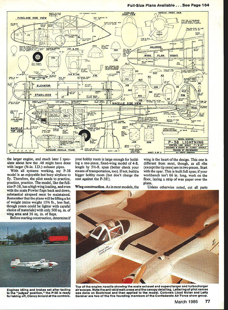
- Ensure your hobby room is large enough for building a one-piece, fixed-wing model of roughly 4 ft. by 5 ft. (also check your means of transportation).
- Gather the plans, tools, and materials called out (balsa sheets, ply, spruce, music wire, hardware, epoxies, CyA, servos, retracts, engines).
Wing construction
The wing is the heart of the design. Note: all ribs (except the tip ones) are in two pieces.
Spar and initial assembly:
- Build the full-span spar. If your bench isn't 66 in. long, work on the floor with wax paper over the plans.
- Spar composition: 1/8-in. sheet balsa web, capped top and bottom with 1/4 x 1-in. straight-grained spruce; the center 24 in. is laminated front and rear with 1/16-in. ply. Assemble over the plans with slow-curing epoxy.
- After epoxy cures, cut slots in the spar for the elevator bellcrank mount and the flap pushrods.
- Position one side of the spar on edge over one side of the wing top view and secure with weights. The "feet" on each rib half provide proper leading-edge (LE) and trailing-edge (TE) height. All ribs except W1F and W1R are installed perpendicular to the bottom surface of the wing panels.
- Use regular (fast) CyA to secure rib halves W2E through W11F and W12 to the spar. Glue the balsa LE and bevel its top to conform with the rib shapes. Similarly, glue the rear ribs to the spar.
- Install both halves of W1, tilted to half the dihedral angle so W1 will be vertical when the wing tips are level.
Top sheeting:
- Edge-glue six sheets of 1/16 x 3 x 36-in. balsa to make one large piece for the wing top sheeting. Place the spar web on the flat building surface, align the sheeting with the LE, trim at the center to rest halfway on W1, and glue on the top sheeting with slow (gap-filling) CyA.
- After the glue has set, turn the wing over and check that the top sheeting is fully glued. Trim to the proper outline.
- Sheet the top of the flap pockets with 1/8-in. balsa and install 1/8 x 1/4-in. strips to form the front of the flap pockets and W13 to form the front of the aileron cutouts.
Opposite panel and elevator pushrod:
- Assemble rib halves for the opposite wing panel to the spar and cover it with the top sheeting. Cut a slot in the top of the left wing for the elevator pushrod.
- Assemble the .062-in. music wire elevator pushrod and control lead-outs to the elevator bellcrank, bolt the bellcrank to its mount, and epoxy the mount assembly through the spar and to the LE.
Flaps and flap linkage:
- Make eight identical flap bellcranks from .062-in. aluminum sheet. Secure a Du-Bro No. 121 E-Z Connector to each with solder. Bolt the flap bellcranks to W14 through W17 with 4-40 screws, washers, and new self-locking nuts.
- Make a 2-bend in one end of each of the eight .055-in. music wire flap pushrods (do not bend the other ends yet). Drill 1/16-in. holes in the front of the flap pockets centered on the 1/4-in. dimension. Harden holes with a drop of CyA.
- Connect flap pushrods to the bellcranks and insert through the holes. Place the screw of the E-Z Connector at W16 through a solder lug, insert a length of .055-in. music wire through the four E-Z Connectors in each wing, position bellcranks parallel, tighten screws, and then glue mounts W14–W17 to the spar, ribs, and LE with CyA.
- Mount the flap servo (or mechanical control) and connect an actuating rod of .055-in. music wire from each end of the servo arm to the solder lug on the screw at each W16. With the servo at "flaps up," bend the aft end of each pushrod so it is parallel to and touching the front of the flap pocket.
- The flaps are made from a 3/8 x 1-1/4-in. balsa strip and 1/16-in. balsa sheets. Size to fit the pockets; note flaps end inboard at W5 and outboard at W6. Use eight 1-in. lengths of 1/4-in. I.D. brass tubing for hinges over the flap pushrod ends, and temporarily mount the flaps with tape. Install flap control horn as drawn on the plans.
- Adjust the E-Z Connectors until all flaps retract together. Impressive when they do.
Sheeting bottom and tips:
- Edge-glue six sheets of 1/16 x 3 x 36-in. balsa for the bottom wing sheeting. Trim the "feet" off the bottoms of the wing ribs and bevel the bottom of the LE to fair in with the ribs.
- Apply sheeting to the bottom of the wing from W12 to the outboard nacelle frame and from the inboard nacelle frame to the fuselage frame with slow-setting CyA. Do not sheet the bottom of the wing tips at this time.
Nacelles
- Cut nacelle frames from 3/8-in. ply: two from the outboard outline and two from the inboard outline. Make one right- and one left-hand version of each.
- Cut 5/8-in. maple engine mounts to length and epoxy them to the nacelle frames. Inboard engine beams stop at the wing LE; outboard beams extend to the wing spar.
- Epoxy correct sets of frames (with engine beams) together over the plans with slow epoxy. Install N1C and N2C (9/16-in. ply) and the landing gear mount (LGM, 1/4-in. ply — use two-ply sheets epoxied together if required).
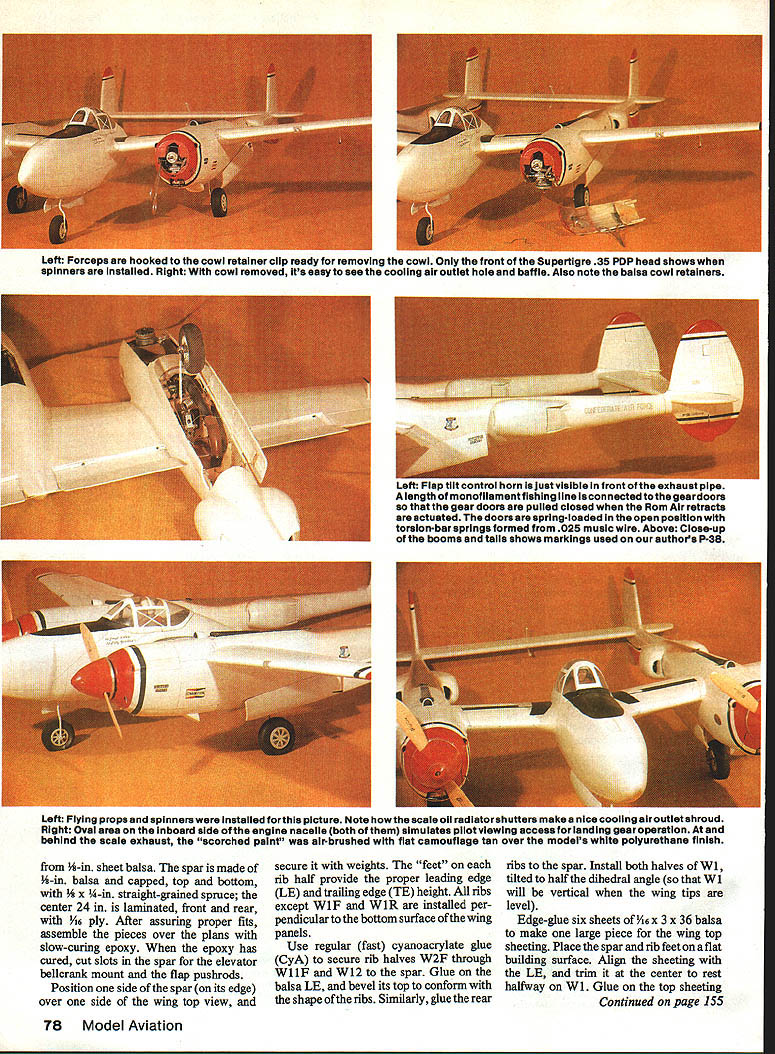
- Epoxy the lower nacelle blocks to the cowl planking and blend cylinder clearance holes into the inside surface of the planking.
- Cut the cowl halves from 1/8-in. sheet and cement to the cowl formers. Carve the cowl latch and retractor bays from hardwood stock and fit to the nacelles.
- Cut out the cowl from the planking and mark cowls R and L. Glue 3/4 x 1/4-in. cowl retainer strips to rear top corners of the cut-out cowl planking and epoxy cowl retainers into the cowl blocks. Bend cowl retainer clips from .055-in. music wire and install above the engine crankshafts.
Cooling and air scoops:
- Drill 1/8-in. holes through nacelle sides and relieve front edges for engine crankcase cooling. Cut air scoops from 1/8-in. O.D. brass tubing and install.
- Cut air inlet holes in the cowl as shown in the plans (large round notches are scale oil radiator air intakes) and cut holes for carburetor air, glow-plug starting connector clearance, and needle valve clearance.
- Fabricate an air outlet baffle of 1/16-in. balsa from N2B to the planking and lower air outlet. The lower air outlet is the scale equivalent of the oil radiator shutter of N25Y.
- Cut supercharger and turbocharger cooling air scoops from balsa or design as required for the version you model. Plans include scale outline of P-38-J and later cowls.
Fuselage
- Cut two fuselage frames and assemble over the plans with F3C, NGM, and F5C. Drill holes for engines and retracts and trial-fit using blind nuts. If blind nuts are loose after removal, secure with epoxy.
- Place fuselage and nacelle frames over the top view, support nacelle frames 1/8 in. above the building surface, trial-fit wing and frames. When satisfied that it all lines up and controls move freely, glue nacelles and fuselage together with slow-acting epoxy.
- Install inboard wing sheeting and nacelle sheeting over the engine mounts. Nacelle tops sheeted with 1/16-in. balsa.
- Install 1/16-in. balsa firewall doublers. Glue in 1/8-in. balsa cowl formers and shape as required.
- Install retract units and ensure doors align with bay openings. Install landing gear dowels and reinforce gear bays with additional ply doublers. Main gear doors are carved to fit and hinged with small piano-wire hinges.
- Install 1/8-in. balsa bottom sheeting and blend seams. Install tailwheel assembly and secure with plated brass bracket. Carve and sand nacelles and fuselage to final outline; sand smooth and seal with lightweight filler where necessary.
- Form and install two flap tilt rods with two small wheel collars on each, as indicated on the plans.
- Make rough cockpits cutout per plans. Use a Sig Acrobat canopy as indicated; modify canopy for "J" or later versions by replacing with flat windscreen made from .020-in. (or thicker) clear plastic, epoxied on the inside (keep epoxy off window areas).
Tail parts
Horizontal stabilizer:
- Build the frame consisting of the LE, spar, SP1 tips, and four center S2s, then set aside.
- Build the elevator and attach to stabilizer with pinned nylon hinges. Support elevator control horn with brass tubing epoxied in place (two places). Note forward slope of the horn when elevator is level. Complete horizontal stabilizer except for 1/16-in. sheeting aft of the spar.
Vertical stabilizer and rudders:
- Build per plans; hinge line frames are tapered to mate with R1 through R4. Side view shows clearance notch in the rudders for the TE of the horizontal stab.
- Sheet top of vertical stabilizers with 1/16-in. balsa down to bottom of R3 and the 1/8 x 3-in. vertical piece. Sheet bottoms with 1/16-in. balsa up to the line from the top of R1 to the bottom of the nacelle side planking.
- Verify elevator control clearance, then install vertical stabilizers. Sheet the rudders and mass balances with 1/16-in. balsa (do not install the rudders at this time).
- Round rudder fronts at hinge line and verify fit around horizontal stabilizer. Secure rudders to vertical stabs with CyA, maintaining 1/4-in. offsets as per plans.
Ailerons:
- Build ailerons using same construction as flaps. Radius aileron front edges and glue in place with CyA while maintaining offsets indicated on the plans. This aileron setting assures control-line tension because the lead-outs exit above the center of gravity; for the same reason there is no right thrust in the engines.
Planking
- Notch first three 1/8 x 1/4-in. nacelle planking strips as shown on the side view. Repeat planking over top view and nacelle formers N1T, N2T, and N4T through N7 (N3T to be added later).
- Make alignment marks on formers for first three planking strips and repeat for second nacelle.
- Alternating side-to-side and top-to-bottom and nacelle-to-nacelle, plank the entire nacelles from N1 to the aft post of the vertical stabilizers using 1/8 x 1/4-in. balsa strips. Secure strips at formers and ends only with fast CyA.
- Install formers and spacers F1 through F10 (except F6) with CyA. Alternating from side to side and top to bottom, plank the fuselage with 1/8 x 3/16-in. strips. Stop forward top planking just aft of F6 location and rear top planking at F7T. CyA-glue F6 in place per plans.
- Cya-glue N3T on top of the wing and under the 1/8 x 1/4-in. planking strip per alignment marks. Keep top planking strip flat for entire length.
Blending and epoxy coating:
- Rough-sand nacelles and fuselage to blend planking strips into smooth curves. Fine-sand, vacuum clean, then mix small batches of slow-curing epoxy and use old playing cards as spatulas to apply epoxy over entire model. Wipe excess epoxy with cards.
Door fitting:
- Due to planking tension, landing gear doors may not fit their original cutouts. Measure the amount of "growth" in door length, place door in a furniture clamp lengthwise and re-bow until it is short for its hole by the measured amount. Coat inside of door with fast-cure epoxy, heat with a heat gun to improve flow and absorption into wood. When epoxy cures, the door should fit closely. Do not mount doors at this time.
Cowl and spinner fitting:
- Trim planking flush with front of N1. Glue balsa blocks to top and sides of nacelle frames with fast-setting epoxy and fillet corners. Lightly tack-glue nose cowl blocks (hollowed to clear engines) to nacelle bottoms, place spinner backplate on engine shaft, mark outline, shape blocks to contour, then remove blocks and cut out the cowl from the planking. Cowl outline is in line with outer surfaces of nacelles.
Detailing
- Carve four radiator pods and glue with CyA to nacelles. Shutter hinge line is shown; I installed hinges and slaved them to each throttle servo to simulate engine temperature control (covered in FAI rules for a flight bonus award, but judges have not awarded points for it so far).
- Epoxy about 2 oz. of lead in the right wingtip against W12 and between the spruce spar strips.
- Epoxy two 1/8-in. lengths of 1/16-in. I.D. brass tubing through W12 of the left wing for lead-out guides.
- Install U/Tronics connector or access cover for mechanical lead-outs as required. Sheet the bottom of the wing tips with 1/16-in. balsa secured with CyA.
- Cut four cowl retainers from 1/8-in. ply and drill 1/16-in. holes in each. Slot cowl block to accept retainers which fit flush against inside of nacelle frames just below engine bearers. Epoxy retainers into cowl blocks. Bend cowl retainer clips from .055-in. music wire and install above engine crank shafts; in two years of flying I have not had a single incident of a cowl coming loose.
Finishing
- Final sanding and priming: finish the airplane except canopy, gear doors, flaps, Pitot tube, and elevator mass balances.
- Pitot tube and elevator mass balances: cut from 1/16-in. ply. Big ends on mass balances are laminated with 1/16 x 1/4-in. balsa, CyA-glued in place, then shaped. Attach with CyA just prior to final painting.
- My airplane is finished in white polyurethane trimmed with red and blue stripes. The Champion sticker came with a set of automobile spark plugs. The rest of the markings were handmade.
- Using slow-cure epoxy, liberally coat inside of engine compartments and cowls. Build and install fuel tanks, install and connect engines to tanks and throttle linkage.
- Install propellers and spinners and balance them.
Flying
- Fill tanks with 10%-nitro (or higher) and tune engines to target rpm (10,000 rpm on 10x6 props recommended).
- Make sure flaps rotate down equally; 39° when fully extended is to scale. Unequal flap movement will cause the flaps to act as ailerons.
- With center of gravity set as shown on plans, taxi model and perform low-speed runs to check trim and control response. Make adjustments to control throws and engine synchronization.
- On takeoff, use full power and keep the model straight with rudder and aileron inputs. Rotate at the recommended speed and climb at a moderate rate. Trim for hands-off flight.
- After each flight, inspect for loose fittings, cracked glue joints, and wear on moving parts. Replace any worn linkages and keep engines tuned. For storage, drain fuel tanks and protect wood surfaces with a light coat of oil.
Documentation and references
Books recommended on the P-38:
- Fork-Tailed Devil: The P-38, by Martin Caidin.
- Lockheed P-38 Lightning, Aero Series Vol. 19.
- P-38 Lightning in Action, Squadron/Signal Publications Aircraft No. 25.
- P-38 Lightning, by Jeffrey L. Ethell, illustrated by Rikyu Watanabe.
Known P-38 locations (at time of writing):
- One in Alaska.
- One owned by Col. Ross of CAF (hangared in Milwaukee, WI).
- One at the front gate of McGuire AFB, NJ (detailed to match Tommy McGuire's last plane, "Pudgy V").
- One at the USAF Museum, Dayton, OH.
- Two at CAF Headquarters: N25Y and a parts carcass to support N25Y.
Contact the CAF to find when and where N25Y or Ross' P-38 will be displayed, as they travel around the country to CAF airshows. In total aircraft, the CAF is the 13th largest air force in the world, and considering many of their planes are "one of a kind," every scale modeler owes them a lot of support. In July 1982 I served as Lefty Gardner's crew chief on N25Y for the weekend — a true labor of love.
Acknowledgments
I would like to thank our "resident expert," Jack Sheeks, for encouraging me to design and build this model and for guidance in the general layout of the plans. Also thanks to Al Pitts for breaking in my .35s right for me.
Happy flying.
Transcribed from original scans by AI. Minor OCR errors may remain.

