
P-39 Airacobra
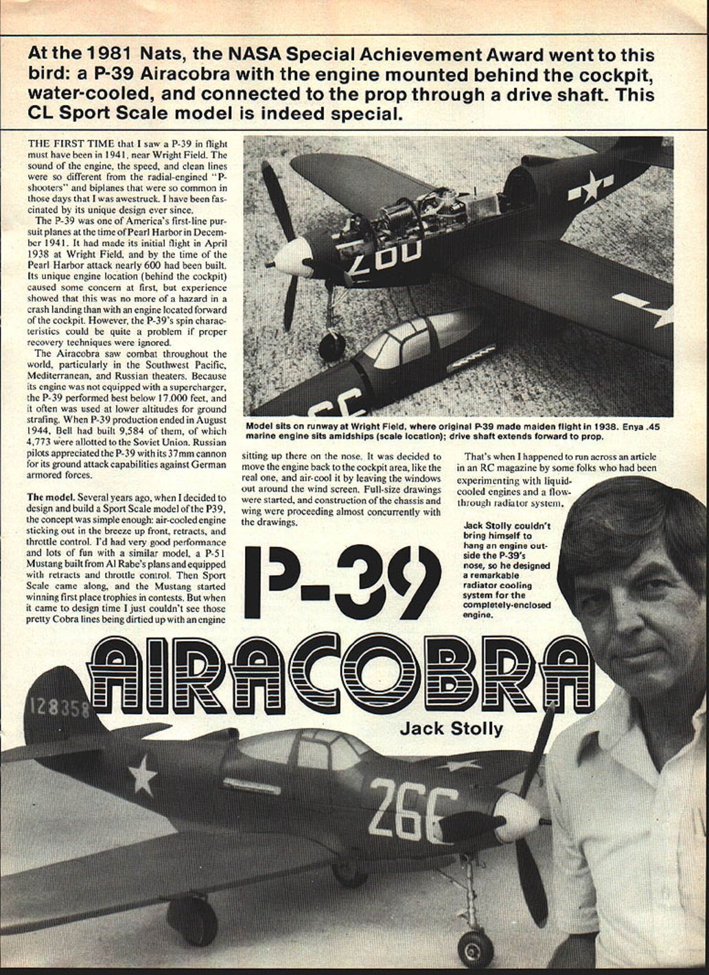
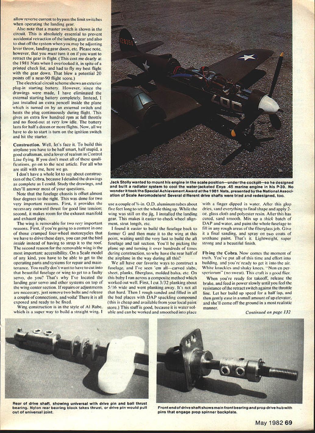
At the 1981 Nats, the NASA Special Achievement Award went to this bird: a P-39 Airacobra with the engine mounted behind the cockpit, water-cooled, and connected to the prop through a drive shaft. This CL Sport Scale model is indeed special.
The first time I saw a P-39 in flight must have been in 1941, near Wright Field. The sound of the engine, the speed, and the clean lines were so different from the radial-engined "P-shooters" and biplanes that were common in those days that I was awestruck. I have been fascinated by its unique design ever since.
The P-39 was one of America's first-line pursuit planes at the time of Pearl Harbor in December 1941. It made its initial flight in April 1938 at Wright Field, and by the time of the Pearl Harbor attack nearly 600 had been built. Its unique engine location (behind the cockpit) caused some concern at first, but experience showed this was no more hazardous in a crash landing than an engine located forward of the cockpit. However, the P-39's spin characteristics could be quite a problem if proper recovery techniques were ignored.
The Airacobra saw combat throughout the world, particularly in the Southwest Pacific, Mediterranean, and Russian theaters. Because its engine was not equipped with a supercharger, the P-39 performed best below 17,000 feet and was often used at lower altitudes for ground strafing. When P-39 production ended in August 1944, Bell had built 9,584 of them, of which 4,773 were allotted to the Soviet Union. Russian pilots appreciated the P-39 with its 37 mm cannon for its ground-attack capabilities against German armored forces.
The model
Several years ago, when I decided to design and build a Sport Scale model of the P-39, the concept was simple enough: air-cooled engine sticking out in the breeze up front, retracts, and throttle control. I'd had very good performance and lots of fun with a similar model, a P-51 Mustang built from Al Rabe's plans and equipped with retracts and throttle control. Then Sport Scale came along, and the Mustang started winning first-place trophies. But when it came to design time I just couldn't see those pretty Cobra lines being dirtied up with an engine sitting on the nose. I decided to move the engine back to the cockpit area, like the real one, and air-cool it by leaving the windows out around the windscreen. Full-size drawings were started, and construction of the chassis and wing proceeded almost concurrently with the drawings.
As luck would have it, Goldberg retracts would just barely fit the model; I didn't have to design and build my own. The P-39 was sized so that a 3-inch diameter spinner and 3-inch diameter main gear wheels would be proper scale. Too many good-looking airplanes are spoiled by wrong-size wheels and music-wire landing gears—landing gears should look like landing gears.
Before commencing construction of the airframe I'd like to describe the major systems of the plane and the learning experiences during the past year.
Cooling system
I was a little apprehensive about the liquid cooling because everyone said it would work. Still, it took a lot of nerve to fire up a brand-new Enya .45 for the first time. I'd run it for a minute or two then shut it off to see the radiator getting hot, then go on getting braver each time. As it turned out, the cooling system has given no problems; it works beautifully.
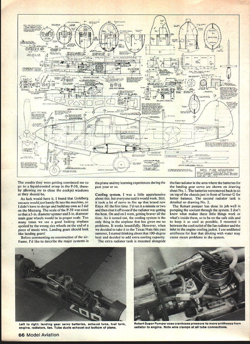
When I decided to take the model to the Texas Nats and started thinking about 100-degree heat, I added extra cooling capacity. An extra radiator tank was mounted alongside the fan/radiator area. Batteries and landing-gear servo shown on drawing sheet No. 1 were moved back to sit on top of the chassis just forward of former "G" for better balance. A second radiator tank is detailed on drawing No. 2. The Robart pumper has done its job well pumping coolant through the system. I mounted the pump between the coolant radiator outlet and the engine cooling jacket. Use undiluted antifreeze; diluting with water may cause steam problems.
The results convinced me to go to a liquid-cooled setup in the P-39, thereby allowing me to close the cockpit windows as they should be.
Drive shaft
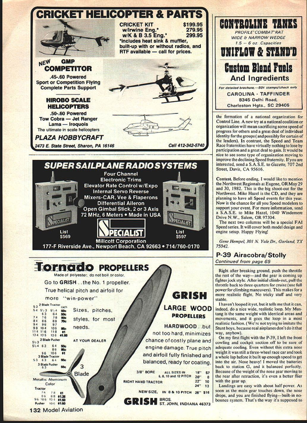
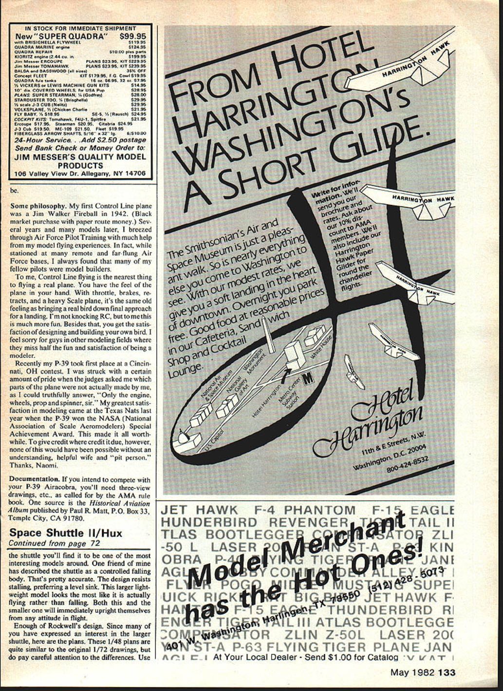
Now here's where I had fun — and you will benefit from my experience. I started by using standard boat parts off the shelf: 3/16-inch diameter drive shaft, screw-on universal, and front prop connection. Forget it! Then I started making drive shafts and various connection systems, all of which failed because setscrews and flats on the drive shaft just wouldn't hold.
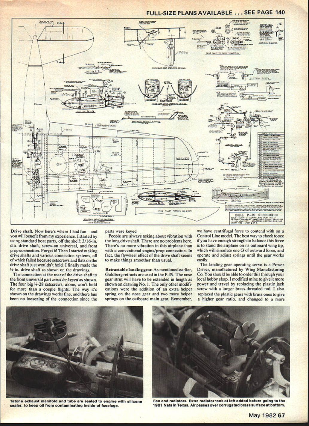
I finally made the 1/4-inch drive shaft as shown on the drawings. The connection at the rear of the drive shaft to the front universal part must be keyed as shown. The four big 1/4-28 setscrews alone won't hold for more than a couple flights. The way it's shown on the drawings works fine, and there has been no loosening of the connection since the parts were keyed.
People often ask about vibration with the long drive shaft. There are no problems here. There's no more vibration in this airplane than with a conventional engine/prop connection. In fact, the flywheel effect of the drive shaft seems to make things smoother than usual.
Retractable landing gear
Goldberg retracts are used in the P-39. The nose gear strut must be extended in length as shown on drawing No. 1. The only other modifications were the addition of an extra helper spring on the nose gear and two more helper springs on the outboard main gear. Remember, we have centrifugal force to contend with on a Control Line model. The best way to check whether you have enough strength to balance this force is to stand the airplane on its outboard wing tip, which simulates one G of outward force, and operate and adjust springs until the gear works easily.
The landing gear operating servo is a Power Driver manufactured by Wing Manufacturing Co. I modified mine to give more power and travel by replacing the plastic jack screw with a longer brass-threaded rod. I also replaced the plastic gears with brass ones to give a higher gear ratio, and changed to a more powerful motor which I run on 6 volts. Operating all three landing gears off one servo takes a pretty powerful servo.
The gear retracts in near-scale time instead of snapping or jerking up and down as you often see on models. Flight judges should give full points here for realistically operating retracts.
Control system
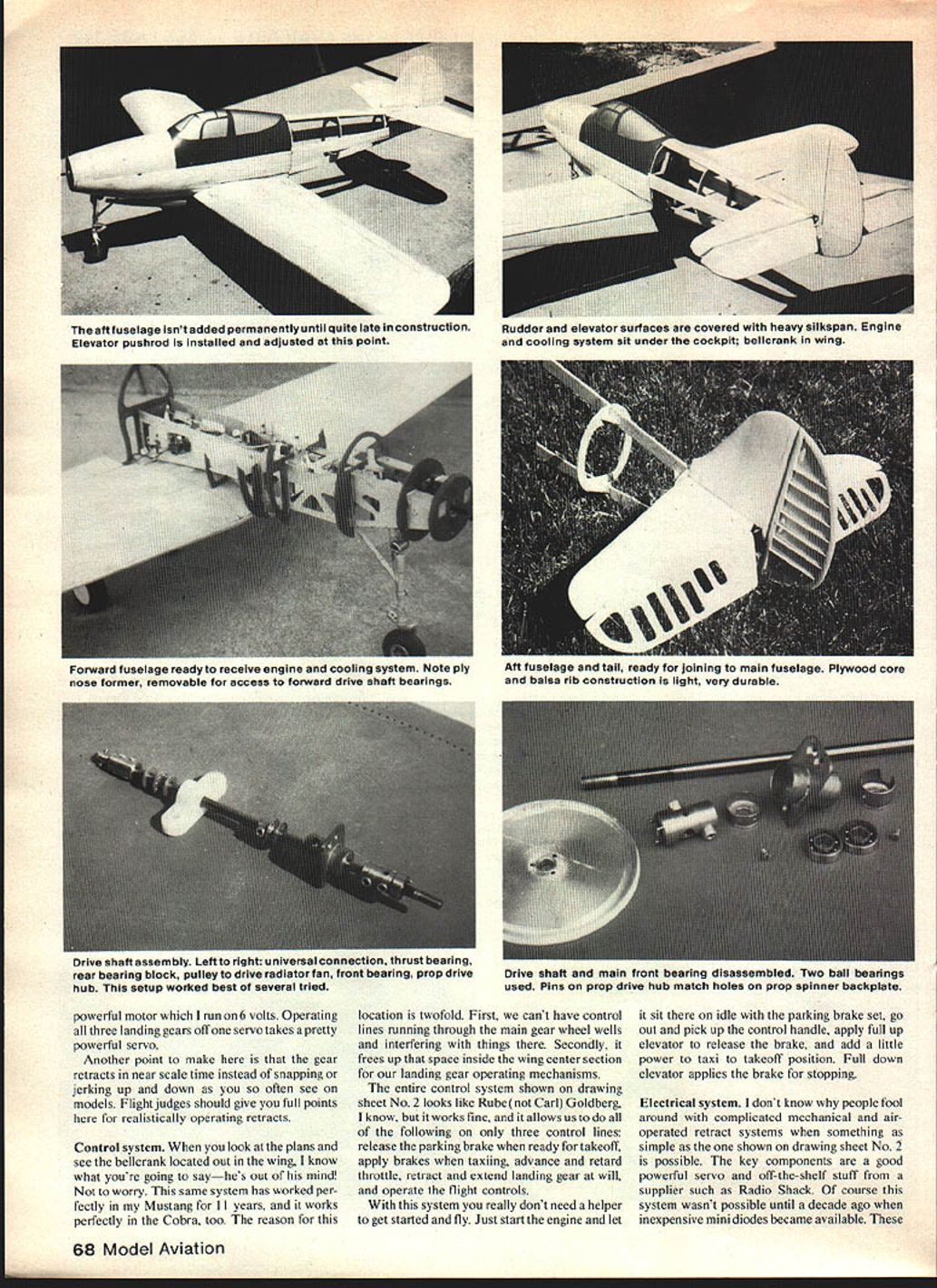
When you look at the plans and see the bellcrank located out in the wing, you might think I'm out of my mind. Not to worry. This same system worked perfectly in my Mustang for 11 years, and it works perfectly in the Cobra, too. The reason for this location is twofold:
- We can't have control lines running through the main gear wheel wells and interfering with things there.
- It frees up space inside the wing center section for our landing gear operating mechanisms.
The entire control system shown on drawing sheet No. 2 looks like Rube (not Carl) Goldberg. I know, but it works fine, and it allows us to do all of the following on only three control lines:
- Release the parking brake when ready for takeoff
- Apply brakes when taxiing
- Advance and retard throttle
- Retract and extend landing gear at will
- Operate the flight controls
With this system you really don't need a helper to get started and fly. Just start the engine and let it sit on idle with the parking brake set, pick up the control handle, apply full up elevator to release the brake, and add a little power to taxi to takeoff position. Full down elevator applies the brake for stopping.
Electrical system
I don't know why people fool around with complicated mechanical and air-operated retract systems when something as simple as the one shown on drawing sheet No. 2 is possible. The key components are a good, powerful servo and off-the-shelf parts from a supplier such as Radio Shack. Of course, this system wasn't possible until inexpensive minidiodes became available; these allow reverse current to bypass the limit switches when operating the landing gear.
A master switch is shown in the circuit. This is absolutely essential to prevent accidental retraction of the landing gear and also to shut off the system when you may be adjusting lever throw, landing gear doors, etc. Please note, however, that you must turn it on if you want to retract the gear in flight. (This cost me dearly at the 1981 Nats when I overlooked it, despite a printed checklist, and had to fly my best flight with the gear down. That blew a potential 20 points off a near-90 flight score.)
The electrical circuit scheme originally showed an exterior plug-in starting battery. Since the drawings were made, I eliminated the external starting battery completely. Instead, I installed an extra pencil inside the plane which is turned on by an external switch and heats the plug continuously during flight. This gives an extra few hundred rpm at full throttle and prevents flood-out at very low idle. The battery lasts for half a dozen or more flights. Now, to start you simply turn on the ignition switch and hit the starter.
Construction
To build this airplane you have to be half smart, half stupid, a good craftsman, and a lover of realism in Control Line flying. If you don't meet all of these qualifications, go on to the next article. For those still with me, here we go.
I detailed the drawings as completely as I could. Study the drawings, and they'll answer most questions.
Note that the fuselage chassis is offset almost four degrees to the right. This was done for two very important reasons: it provides the necessary outward thrust for good line tension, and it makes room for the exhaust manifold and exhaust pipe.
The wing is removable for two important reasons:
- If you're going to a contest in one of those cramped four-wheel vehicles we have to drive these days, you can put the bird inside instead of strapping it to the roof.
- Accessibility: on a scale model you must be able to get to the operating parts and systems for repair and maintenance. You don't want to cut into the fuselage or wing to get to a faulty servo. That's why I've located the landing gear servo and other systems on top of the wing center section. If repairs or adjustments are necessary, just remove two bolts and release a couple of connections.
Wing construction is in the style of Al Rabe, which is a superb way to build a straight wing. I use a couple of 8-inch O.D. aluminum tubes about five feet long to set the whole thing up. While the wing was still on the jig, I installed the landing gear to make it easier to check wheel alignment and strut length.
I found it easier to build the fuselage back to former G and then mate it to the wing at that point, waiting until the very last to build the aft fuselage and tail section. You'll be picking the plane up and turning it over hundreds of times during construction, so why have the rear half of the airplane in the way?
We all have our favorite ways to construct a fuselage—carved slabs, sheet, planks, fiberglass, molded balsa, etc. On this model I used a composite method that worked well. First, I cut 3/32-inch planking about 5/16-inch wide and applied the planking. Then I rough-sanded and filled bad places with DAP spackling compound. This stuff is water-soluble and can be worked and smoothed with a finger dipped in water. After it dries, sand everything to final shape and apply 2 oz. glass cloth and polyester resin. After curing, sand smooth. Mix up a thick batch of DAP and water and paint the whole fuselage to fill any rough areas of the fiberglass job. Give it a final sanding and spray on two coats of urethane paint. The result is lightweight, super strong, and a beautiful finish.
Flying the Cobra
Now comes the moment of truth. You've put all this time and effort into building, and you're ready to get it into the air. This craft is a good flier.
When ready for takeoff, release the brake and feed in power slowly until you feel the resistance of the retract switch against the throttle line. Let her build up speed for a half lap, then gently ease in a small amount of elevator, and she'll come off the ground in a most realistic manner. Right after breaking ground, push the throttle the rest of the way—and the gear comes up fighter-jock style. After initial climb-out, pull the throttle back to three-quarters for cruise (use full power for climbing maneuvers). This makes for a more realistic flight: no tricky stuff and very stable.
I haven't looped it yet, but it feels capable of a nice wide, realistic loop. My Mustang is the same weight with identical areas and moments, and it does a realistic loop. We're not trying to imitate the stunt boys; real airplanes don't fly that way.
On my first flight with the P-39, I left the front cowl and cockpit section off to be sure of adequate cooling. Even without this extra nose weight it was still a three-wheel race car and took a whole lap before it built up enough speed to get into the air. If the model is nose-heavy, move the batteries back to station G and it will balance. Because of the weight of the nose gear moving to the rear after retraction, it's an even better flier with the gear up.
Landings are easy with about half power. As soon as the main gear touches down, the nose drops, and you are finished flying—built-in no-bounce system. That's the way it's supposed to be.
Some philosophy
My first Control Line plane was a Jim Walker Fireball in 1942 (black-market purchase with paper-route money). Several years and many models later, I breezed through Air Force Pilot Training with much help from my model flying experiences. While stationed at many remote and far-flung Air Force bases, I often found that many fellow pilots were model builders.
To me, Control Line flying is the nearest thing to flying a real plane. You have the feel of the plane in your hand. With throttle, brakes, retracts, and a heavy scale plane, it's the same feeling as bringing a real bird down final approach for landing. I'm not knocking RC, but to me this is much more fun. Besides that, you get the satisfaction of designing and building your own bird. I feel sorry for modelers in other fields who miss half the fun and satisfaction of being a modeler.
Recently my P-39 took first place at a Cincinnati, Ohio contest. I was proud when the judges asked which parts of the plane were not actually made by me; I could truthfully answer, "Only the engine, wheels, prop and spinner, sir." My greatest satisfaction came at the Texas Nats when the P-39 won the NASA (National Association of Scale Aeromodelers) Special Achievement Award. That made it all worthwhile. None of this would have been possible without an understanding, helpful wife and "pit person." Thanks, Naomi.
Documentation
If you intend to compete with your P-39 Airacobra, you'll need three-view drawings, etc., as called for by the AMA rule book. One source is the Historical Aviation Album published by Paul R. Matt, P.O. Box 33, Temple City, CA 91780.
Transcribed from original scans by AI. Minor OCR errors may remain.

