
P-51 MUSTANG
Steve Kerry
Ask the average power flier, and they will tell you that scale models take a long time to build, are heavy and difficult to fly, are only brought out when the weather is perfect, and of course, they cost a lot of money. Ask the same average flier about electric power, and they will talk about heavy, underpowered, very fragile aircraft that fly so slowly they can hardly get out of their own way.
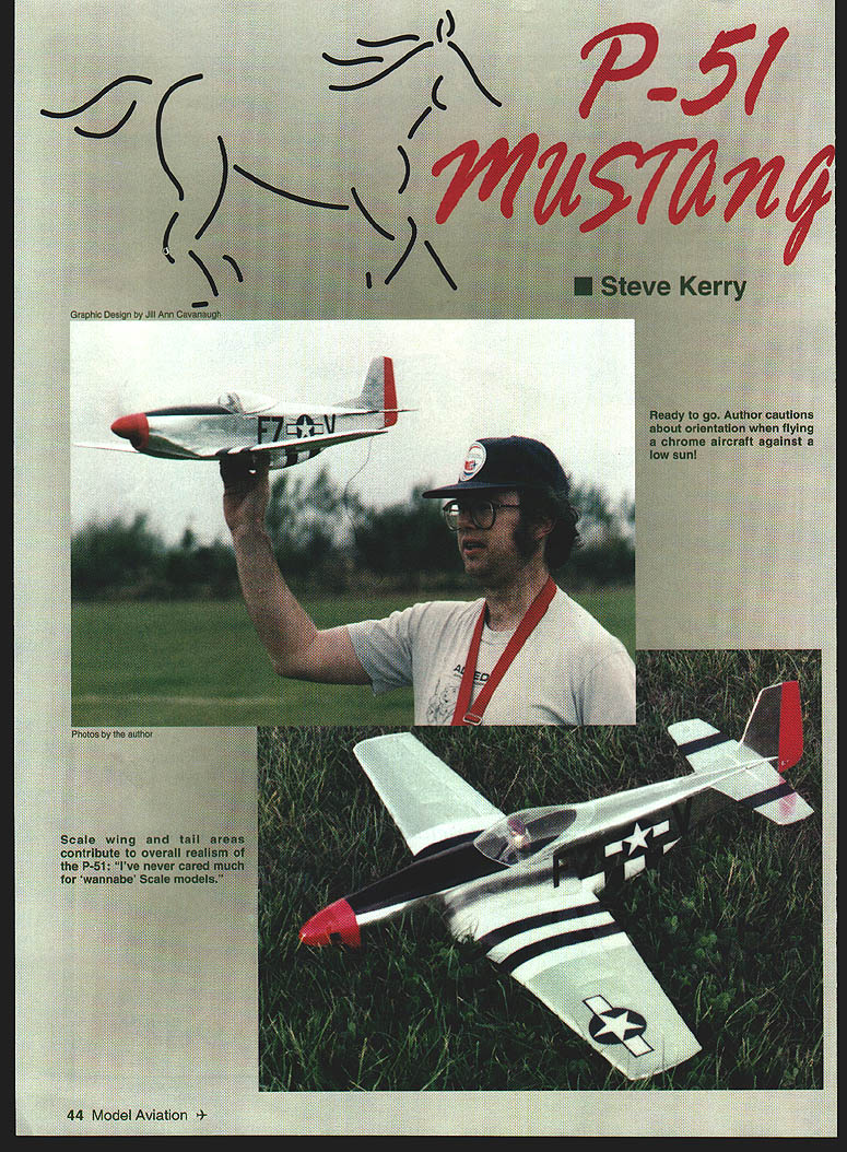
So when you tell them you're building a scale P-51 Mustang that is powered by a little Speed 400 motor and can be flown like a sport model, they'll probably laugh at you—until you fly it.
I've never cared much for "wannabe" scale models. You know the sort of thing: a guy takes an Ugly Stick and paints a camouflage pattern on the wings, adds a couple of roundels, and calls it a semi-scale Spitfire. Yuk! I'm a sport flier, not a rivet-counter, but if a subject can be modeled accurately and still fly well, then I don't see the point in simplifying it.
When I decided to build a series of electric warbirds for Speed 400 power, I wanted to see if it was practical to build accurate models that would still be suitable for sport flying. The Mustang is the first of that series to be completed.
A quick bit of math showed that a 1/12-scale model (32-inch span) would have more wing area than a Speed 400 pylon racer, and a target weight of 17 ounces would give good performance on seven cells.
I like the little Speed 400 motors; they have their limitations, but if you stay within those limitations you can have a lot of fun.
This is not an airplane for beginners, but if you have flown a low-wing design before, then you will have no trouble here. The Mustang will not survive repeated crashes as a trainer would, although most damage can be repaired without too much drama (a tree jumped out in front of me once and removed half the wing, but the airplane was flying again the next day).
All horns and pushrods on the prototype are internal, but if you want to hang them out in the breeze, I'm sure it will still work. Looks pretty ugly, though.
I assume you already have your favorite method of radio installation, and can place the various components to achieve the correct center of gravity (CG). The most important thing is that you select your wood with care and build accurately; there is no point trying to fill a bad joint by pouring in extra glue.
CONSTRUCTION
Wing
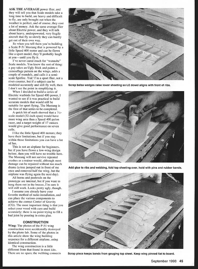
The photos of the P-51 wing construction were accidentally destroyed by the photo lab. Some of the photos in the article show the wing building sequence for a different airplane, using identical construction.
The wing construction is a little different from that found in most kits. There are no spars; the webbing connects directly to the top and bottom sheeting and is quite strong for a wing of this size. Thinner or longer wings may need a strip of hard balsa incorporated into the sheeting where it meets the webbing, but spruce is not necessary and carbon fiber would be complete overkill.
The entire wing is made from 1/16" sheet, with the exception of the leading edge (1/8" dowel) and the dihedral brace (3/32" hard balsa). Be sure you use very hard 1/16" strips for the trailing edge; the prototype only used medium balsa and had to be strengthened later as a result. Note the center-section sheeting on the plan tapers out to R5; the prototype did not have this feature, and a stress riser occurred at the aileron root.
Start construction by cutting a 45° angle down one side of the leading-edge sheeting. You can get a cheap bevel cutter from any art supplier; they are used to cut mat boards for picture frames. I used a Logan cutter. Put your straightedge on the LE sheet, run this handy little gadget down the side, and you have a perfect bevel. Cut two sheets this way, glue the 1/8" dowel to one of them, and let it dry.
Lay all the bottom sheeting on the plan and pin it down, including the lower LE sheeting with the attached dowel. Pin the LE sheeting at the rear edge only. Because of the kinked wing, you will have to use two pieces of LE sheet for each panel.
Glue everything together and add the ribs; check the position of each rib by lifting the LE dowel and sliding the rib forward to meet it. Glue the rear half of each rib in place, remembering the double rib at R4 and the dihedral angle on R1.
When everything is dry, pack up the LE with small triangles of scrap balsa and glue it to the ribs. Be sure that the rear of each rib is flat on the board. When this is dry, cut a slot in ribs R1–R4 and install the dihedral brace.
Because the wing taper changes at R4, the top edge of the brace is not a straight line; if you cut it straight, this will show at R5 and create a weak point. Use more 1/16" sheet to add the vertical webbing; this extends from the dihedral brace to the wingtip and should be a snug fit—cut carefully! When dry, sand down any high spots on the webbing so it fits flush with the top of the ribs. Add a strip of hard 1/16" sheet along the TE, cutting the ribs back to suit.
Take the other piece of LE sheeting and lay it on the wing, sliding it forward so the beveled edge sits snugly on the dowel. Cut to size and tape it to the LE dowel, then fold it forward like a hinge and run glue along the joint. Add glue to the ribs and webbing, and fold the LE sheeting down into place. Hold with rubber bands or tape until dry, then add the top capstrips and TE piece.
When everything is dry, remove it from the board and you will find that the wing is surprisingly light and strong. You did remember to add 1/8" washout, didn't you? If not, it can be added when covering.
Build the second wing onto the first, fitting the tip so the dihedral brace sits flat. You may find it easier to fit the wing dowel to R1 before sheeting the top of the second wing; an offcut from the LE dowel is fine. The traditional 1/2-inch bandage and epoxy around the center section is important; you will also need a piece at R4 from the LE back to the dihedral brace.
I prefer to use torque rods for ailerons; they have far less slop than control snakes. Cut a length of 1/16" wire to suit. Cut a narrow strip of ordinary paper, rub a glue stick down one side, and wrap it around the wire in a spiral pattern with the glue on the outside. When this is dry, trim the ends and you have a thin, light sleeve that fits perfectly over the wire and permits smooth rotation.
Bend one end of the wire and solder on a brass tube, which is then flattened and drilled to take the aileron horns. Slide the paper tube into place, then bend the other end of the wire and cut to fit the aileron. The paper tube can also be formed around the torque rod after making the bends, if you forget to fit it first like I did! Of course, you could just use a commercial torque rod linkage; I started out this way, but the homemade version is smaller and lighter.
The entire trailing edge for each wing, including the aileron, is made from a single piece of balsa. I used to build up ailerons as part of the wing ribs and cut them away later, but at this size it is just as light (and much faster) to make the TE from balsa sheet and cut the aileron away later.
Glue the root piece to the wing, cut a groove to take the torque rod sleeve, and glue it into place. Add a scrap of 1/32" plywood to the top and bottom of the wing root to take the nylon wing bolt, and drill to suit.
I top-hinged my ailerons with the covering film; this works fine and provides an airtight seal that matches the finish. Since the hingeline of the aileron and torque rod are not quite in line with this method, you will need to slip another piece of paper tube over the end of the wire and cut a matching slot in the aileron. When the tube is glued into this slot, the wire is free to slide back and forth as the control surface moves.
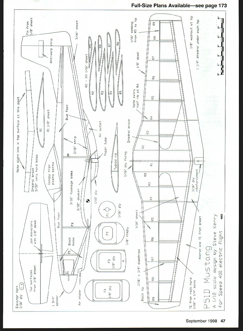
P-51D Mustang — plan notes and parts
- P-51D Mustang: a 1/2-scale design by Steve Kerry for Speed 400 electric flight
- Fin from 1/8" sheet
- Anti-warp strip
- R1: 1/16" sheet
- R2–R9: 1/16" sheet
- 3/16" strip
- Blue foam (top deck and scoop)
- Air outlet
- Paper tube (torque rod sleeve)
- 1/8" ply (various doublers and formers)
- F1–F4: 1/8" ply formers
- Block balsa for nose and tips
- 3/32" fuselage sides; fuselage side doublers (3/32")
- 1/16" ply capstrips; 1/16" x 1/4" capstrips
- Typical rib details, dihedral brace, 1/8" dowel LE
- Note: center hole from R5 to tip
- 1/16" ply facing; 1/16" sheet sheeting
- T/E from sheet; T/E front & rear 1/16" x 1/8" balsa
- Block tip and 1/16" ply rear capstrips
- Aileron cut-out; join elevators with 1/8" dowel
- Elevator horn: 1/16" ply
- Tail surfaces from 1/8" sheet; 1-3/4" spinner
- Air intake and scoop facing: 1/16" ply
Fuselage
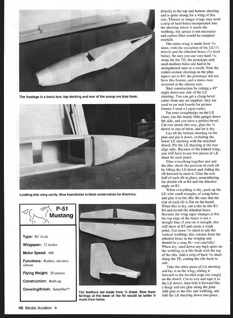
The fuselage is a basic box with 3/32" sheet sides and a blue foam top, 3/16" light sheet underside at the rear, and 3/16" triangular strip in the corners. Cut the sides, add the formers, and pull in at the nose and tail when dry.
The upper fuselage sides are flat so you can build the fuselage inverted on the board, or preferably in a fuselage fixture. Add the balsa blocks around the nose; hollow the blocks for lightness. Be sure to open the intake under the nose—this provides essential ventilation for the electric gear. The top deck and rear half of the air scoop are carved from blue foam, which is easily shaped with a sanding block.
The tail surfaces are cut from medium 1/8" sheet; don't forget the anti-warp strip in the fin.
The elevators are joined with another offcut of LE dowel and the elevator horn is cut from 1/16" plywood. The prototype tail fairings are made from blue foam, but this was a real pain; soft balsa would be far easier. Tack-glue the fairing pieces to the fuselage with scraps of 1/8" sheet to represent the tail surfaces, sand everything to shape, and remove the blocks again.
Cover the tail surfaces, including the fairings, and glue them all together, but do not attach them to the fuselage until after covering. Fit the plywood retaining plate to the wing cutout. Drill and tap it according to your wing bolt. I used a hollowed piece of block balsa for the forward part of the scoop, but you can just as easily make it from 1/4" sheet. Face it with 1/16" plywood, and remember that this will be the first part to contact the ground when landing.
Screw the wing in place and sand the scoop smooth. When the airplane is assembled, the joint should be virtually invisible. You will need to make a paper tube slightly larger than the wing bolt head to fit inside the scoop and guide the wing bolt into place.
Cut an air outlet into the back of the scoop; the full-scale Mustang had a radiator flap here, but I cut a nonscale hole and painted it black. When I put the invasion stripes on the lower fuselage, I made sure the outlet was lined up with a black stripe, and it is almost impossible to see.
Covering
I covered the prototype with chrome Solarfilm, which was adequate but not brilliant for this application; polished aluminum Fibafilm would be a better alternative.
The ailerons were taped in place and the top of each wing was covered in a single piece. Then the ailerons were flipped back over the wing, and the underside covered with another piece that stopped just short of the torque rod. The paper tube was then glued firmly to the aileron—check that the surface does not bind—then the last bit of the aileron is covered. If you are adding invasion stripes (highly recommended for visibility), this part of the aileron will be under a stripe anyway.
If you have never flown a chromed model before, watch out for orientation problems.
Pick a flashy color scheme for your Mustang—the brighter the better! Normally I test-fly my models with just basic blocks of color, and only add details after they have been proven in the air (an advantage of electric flight; you can't do that with a slinky glow engine). The Mustang is an exception.
I chose a red nose and rudder, with invasion stripes on wing and lower fuselage. Stars-and-bars were added from plastic film, along with registration letters and a black panel on the nose.
The canopy is made from a plastic bottle, formed over a blue foam plug. This is quick and easy, and the price is right! The curvature was quite steep, and I had to make the canopy in front and rear sections and glue in place. Please install a pilot — the cockpit is highly visible and it looks pretty silly flying around with nobody at home.
My target weight of 17 ounces was a little optimistic. The prototype ended up weighing 20 ounces, but if I built another, I'm pretty sure I could manage 18 ounces.
Flying
Balance the model where shown for the first couple of flights, and adjust the control throws to 1/8" all around. My first flight had the ailerons at twice this movement; it was a wild ride!
The air scoop makes a convenient handgrip for launching. Throw it like a javelin, straight and smooth. Give it a couple of seconds to get up speed, then pull into a climbing turn and watch the sunlight flash off those wings.
Keep it close until you are familiar with the airplane—these little models can get very small in a short amount of time.
The Mustang will go wherever you point it. Low passes are particularly impressive. With the power off, the glide is everything you would expect from such a clean design. Stalls are gentle and straight, provided you built the wing accurately in the first place. The prototype can be slowed down to almost walking pace for landing. If you have a sealed surface at your flying site, you might even install a set of Robart mini retracts!
I hope this has convinced you to try one of these little models. The cost-to-fun ratio is unbeatable, and if you start now, you can be flying it next week!
Steve Kerry 278 Victoria Ave. HULL HU5 3DZ England metaphor@enterprise.net
Transcribed from original scans by AI. Minor OCR errors may remain.

