
P-82 Twin Mustang
By Barry Baxter
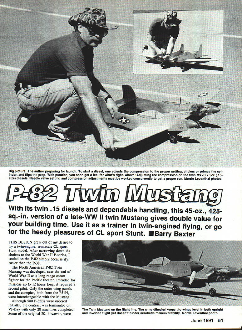
With its twin .15-size diesels and dependable handling, this 45-oz., 425-sq.-in. version of a late–WWII Twin Mustang gives double value for your building time. Use it as a trainer in twin-engined flying, or go for the heady pleasures of CL sport Stunt.
This design grew out of my desire to try a twin-engine, semi-scale CL sport Stunt model. After narrowing down the choices to the World War II P-series, I settled on the P-82 simply because it's easier than the P-38.
The North American P-82 Twin Mustang was developed near the end of World War II as a long-range escort fighter for the Pacific theater. Intended for missions up to 12 hours long, it required a second pilot. Only the outer wing panels and the canopies, both from the P-51H, were interchangeable with the Mustang.
Although 500 P-82Bs were ordered initially, the contract was terminated on VJ Day with only 20 machines completed. Some of the original 20, however, were converted to P-82C and P-82D night fighters (differentiated by the type of radar pod installed below the wing center section). Packard Merlin engines were used.
In the fall of 1946, 100 P-82E escort fighters were ordered, together with 100 P-82Fs and 50 P-82Gs as night-fighter variants. Allison V-1710 engines changed the power profile. As the only planes in the Air Force fleet with enough range to operate out of Japan, these P-82s saw service in the Korean War, both as fighters and in ground-attack roles. Another variant, the F-82, claimed the first kill of the war on June 27, 1950. Removed from operational service in 1953, it was the last of the piston-engined fighters in the Air Force.
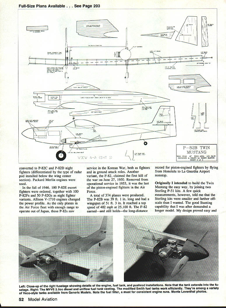
A total of 374 planes were produced. The P-82B was 39 ft. 1 in. long and had a wingspan of 51 ft. 3 in. It reached a top speed of 482 mph at 25,100 ft. The F-82 earned—and still holds—the long-distance record for piston-engined fighters by flying from Honolulu to LaGuardia Airport nonstop.
Originally I intended to build the Twin Mustang the easy way, by joining two Sterling P-51 kits. A few quick measurements, however, told me that the Sterling kits were smaller and farther off-scale than I wanted. The good stunting capability that I was after demanded a larger model. My design proved easy and relatively inexpensive to build; it's a satisfying flier and also looks authentic.
Since two new MVVS 25cc .15-size diesels were waiting to be broken in, a twin-engined model seemed exactly right. Another motive, too, was to silence skeptics—folks who insist that getting two diesels to operate simultaneously just can't be done. It took about half a dozen flights to break the diesels in; after the first few laps both engines were still running and, once synchronized, they showed off the Twin Mustang's capabilities.
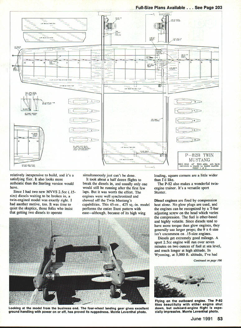
This 45-oz., 425-sq.-in. model performs the entire Stunt pattern with ease, although because its wing loading is a little high, the square corners are a bit wider than I'd like. The P-82 also makes a wonderful twin-engine trainer.
Diesel engines fire by compression (heat) alone; no glow plugs are used. The engines can be recognized by the T-bar adjusting-screw head, which varies compression. Diesel fuel is ether-based and highly volatile. Since diesels tend to have more torque than glow engines, larger props are generally used; a 9 x 6 isn't uncommon on .15-size engines. Diesels get extremely good mileage — a sport 25cc engine will run over seven minutes on two ounces of fuel at sea level; at higher altitude (Wyoming, 5,000 ft.) I've seen longer run times. In some cases, two ounces last for over 15 minutes.
To start a diesel engine, adjust the compression to the proper setting, choke or prime the cylinder, and flip the prop. This requires some practice, but you soon develop a feel for it. You must work the needle-valve setting and the compression adjustments concurrently to get a proper run. If the engine sounds as though it's laboring hard, it's probably over-compressed; if it's burping like a World War I rotary engine, it's under-compressed. Whether rich or lean, runs sound about the same as they do with a glow engine.
The biggest problem with twin diesels is the weight of the running gear. The MVVSs weigh 6-3/4 oz. each, and the additional tank, prop, and spinner increases the entire gear load up to 18 ounces. That's very heavy for what is basically a .30-powered airplane; two Fox .35s would have given the same weight penalty. (Of course, the .35s require 1/8-in. balsa for the fuselage and even larger fuel tanks, so they'd have weighed the plane down still more. But in compensation I'd have had a .70-powered model.)
I've had good luck with the MVVS diesels. They start quite easily and give consistent runs with lots of power. Though they come with two venturis and a crankcase pressure fitting, I've never used any of the higher-power setups. I've used the MVVSs in Combat models with about 360 sq. in. of wing area; with the same fuel tank setup as in the P-82 and turning 8 x 6 Taipan props, they'll easily attain maximum speed.
I use 8-1/2 x 6-1/2 Kev-Up props on the P-82 primarily because I've used them and they work quite well, but since I haven't experimented with anything else I have no idea whether they're optimal. Although the sound is a little big for .15s, the two engines work synergistically to produce the power of a .30, and you run more pitch than is usual with a single engine to gain the power advantage of the twin setup. In all other respects, performance is essentially like that of a single engine. The MVVS diesels are available for approximately $85 from Carlson Engine Imports, 814 East Marconi Ave., Phoenix, AZ 85022.
P-82 Mustang / Baxter
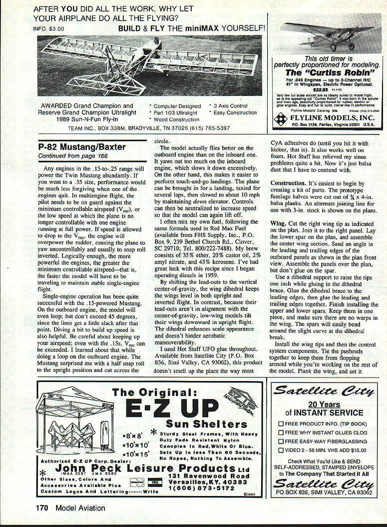
Any engines in the .15-to-.25 range will power the Twin Mustang abundantly. If you went to a .35 size, performance would be much less forgiving when one of the engines quit. In multiengine flight, the pilot needs to be on guard against the minimum controllable airspeed (Vmc), or the low speed at which the plane is no longer controllable with one engine running at full power. If speed is allowed to drop to the Vmc, the engine will overpower the rudder, causing the plane to yaw uncontrollably and usually to snap roll inverted. Logically enough, the more powerful the engines, the greater the minimum controllable airspeed—that is, the faster the model will have to be traveling to maintain stable single-engine flight.
Single-engine operation has been quite successful with the .15-powered Mustang. On the outboard engine, the model will even loop; but don’t exceed 45 degrees, since the lines get a little slack after that point. Diving a bit to build up speed is also helpful. Be careful about keeping up your airspeed, even with the .15s. It can be exceeded. I learned about that while doing a loop on the outboard engine. The Mustang surprised me with a half snap roll to the upright position and cut across the circle.
The model actually flies better on the outboard engine than on the inboard one. It yaws out too much on the inboard engine, which slows it down excessively. On the other hand, this makes it easier to perform touch-and-go landings. The plane can be brought in for a landing, taxied for several laps, then slowed to about 10 mph by maintaining down elevator. Controls can then be neutralized to increase speed so that the model can again lift off.
I often mix my own fuel, following the same formula used in Red Max Fuel available from FHS Supply, Inc., P.O. Box 9, 239 Bethel Church Rd., Clover, SC 29710; Tel. 800/222-7488. My brew consists of:
- 35% ether
- 20% castor oil
- 2% amyl nitrate
- 43% kerosene
I’ve had great luck with this recipe since I began operating diesels in 1959.
By shifting the lead-outs to the vertical center-of-gravity, the wing dihedral keeps the wings level in both upright and inverted flight. In contrast, because the lead-outs aren’t in alignment with the center-of-gravity, low-wing models tilt their wings downward in upright flight. The dihedral enhances scale appearance and doesn’t hinder acrobatic maneuverability.
I used Hot Stuff UFO glue throughout. Available from Satellite City (P.O. Box 836, Simi Valley, CA 93062), this product doesn’t smell up the place the way most CYA adhesives do (until you hit it with thick kicker, that is). It also works well on foam. Hot Stuff has relieved my sinus problems quite a bit. Now it’s just balsa dust that I have to contend with.
Construction
It’s easiest to begin by creating a set of parts. The prototype fuselage halves were cut out of 3/32 x 4-in. balsa planks. An alternate joining line for use with 3-in. stock is shown on the plans.
Wing
- Cut the right wing tip as indicated on the plan. Join it to the right panel.
- Lay the lower spar on the plan, and assemble the center wing section.
- Sand an angle in the leading and trailing edges of the center wing panel as shown.
- Assemble the panel, keeping all the ribs in place.
- Use a dihedral support to raise the tips while gluing in the dihedral brace. Glue the dihedral brace to the leading edges; glue the leading and trailing edges together.
- Finish installing the upper and lower spars. Keep them in one piece, and make sure there are no warps in the wing. The spars will easily bend around the slight curve at the dihedral break.
- Install the wing tips and then the control system components. Tie the pushrods together to keep them from flopping around while you’re working on the rest of the model.
- Plank the wing, and set it in the circle.
Fuselage
Make sure you've cut out both a right side and a left. Assemble all the balsa parts including the doublers and engine mounts. Maintain a solid doubler on the outboard side of the fuselage by using plywood shims for the engine. These will prevent the case from extending through the fuselage. Don't install the belly scoop at this point.
Assemble the rudder, and attach it to the fuselage. Sand the fuselage sides to shape, then fair in the rudder. Glue the sides to the wing, and install the stabilizer through the slots in the fins. Make sure everything is square.
Hinge the center flap and elevator, taking care to keep glue out of the hinge line. I used standard nylon hinges with pins. Install the rudder. Connect the pushrods. Adjust the travel to equal amounts of Up and Down; make sure the flaps and elevators are at the neutral position together.
I gave the flaps about 20 degrees of travel and used 40 degrees for the elevator. Though it's been the subject of much debate, that ratio works for me. Additional flap travel could slow the model to its dreaded Vne threshold. Still, you're welcome to try a different ratio (1:1, for instance), as long as you don't tilt the balance in the wrong direction. If you allowed more flap than elevator travel, you'd be courting disaster.
Install the bottom scoop and the outboard fixed flaps. Glue the landing gear into the plywood fuselage and notches. This is a rugged gear. It even survived the harsh finale to that unplanned half-snap roll when the model slowed down too much on the outboard engine.
Covering and finishing
Give the structure a thorough sanding, and you're ready for covering and finishing. I covered the prototype in aluminum MonoKote and painted it with Formula U Flight Silver. Be sure the silver is clear-coated. Otherwise it's guaranteed to come off and make a sorry mess. I used Black Baron Clear — the second time around. The trim lines were done with tape.
Be extremely selective about covering materials if you're using diesel power; many of the plastic iron-ons will shrivel up after a few weeks' exposure to diesel fuel and exhaust. The only materials I can recommend at this point are MonoKote and colored Micafilm. Paint is acceptable, except for the aforementioned silver—and that stuff comes off even with no fuel around.
The prototype uses modified Smith fuel tanks with uniflow venting, available from Generic Models, 521 Jansen Ave., San Dimas, CA 91773. Generic makes a variety of Veco-style tanks with standard or uniflow venting. Mounting the tanks required moving the stock plumbing to clear the fuselage. Glue them into the slots in the fuselage with UHU. With uniflow venting, the vent is submerged in the fuel so that a vacuum builds up above the fuel and reduces head pressure in the tank. As the engine leans out, the model picks up speed and more air is rammed into the tank. Fuel head pressure and fuel flow increase; then the mixture leans, slowing the plane down. Apparently the theory is a sound one, because these tanks work efficiently.
Check the balance point. The center-of-gravity should either match that shown on the plans or be within 1/2 in. forward of it. Adjust the balance as necessary by adding weight to the appropriate area. The prototype balanced without added weight.
Flying
Starting the left engine first prevents your getting your hand in the running engine while trying to flip the other prop. Since this airplane performs better on the outboard engine alone than on the inboard engine, it's no problem if the inboard engine quits first.
A predictable flier, the P-82 does extremely well on two engines—and with .15s, there are no surprises when one engine quits. As noted earlier, however, the airspeed becomes more critical on one engine. If you want to do single-engined aerobatics, make sure you've built up enough speed to complete a given maneuver. Novice fliers had best not attempt this.
The P-82 Mustang gives you the flexibility of two planes in one. Use it to learn the characteristics of twin-engine models, then move on to the sheer exhilaration of Control Line sport Stunting. Or skip the trainer step entirely, and enjoy the model for its full aerobatics capabilities. The choice is yours.
Transcribed from original scans by AI. Minor OCR errors may remain.

