
Pacer 15
THIS DESIGN is a state-of-the-art F1A model which combines a proven circle-tow mechanism with a strong, lightweight structure reinforced with carbon-fiber and fiberglass materials. The result is a model that gives high performance and consistency. The Pacer is not intended as a beginner's model, but like all good contest designs, the model is simple to build.
I had been flying Nordic Glider for quite a few years when, in 1977 I was transferred to the Los Angeles area. I quickly discovered that, if I was going to compete in that hotbed of glider activity, I would have to design an improved glider and dedicate a lot more effort to preparing for competition.
Since that time I have built 20 models in the series which I call Pacer. Each has been different, and many ideas were tried and discarded. The most all-round successful design thus far has been the Pacer 15, which incorporated lighter wing tips and tail structures with a glide-rudder delay.
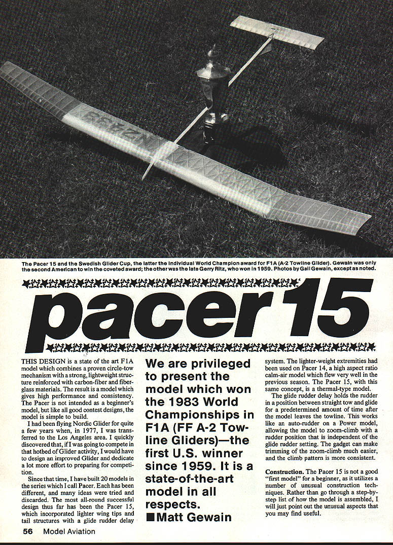
We are privileged to present the model which won the 1983 World Championships in F1A (A-2 Towline Gliders)—the first U.S. winner since 1959. It is a state-of-the-art model in all respects. — Matt Gewain
Design highlights
- Lighter-weight extremities: lighter wing tips and tail structures for improved response and reduced rotational inertia.
- Glide-rudder delay: holds the rudder in a position between straight tow and glide for a predetermined time after release, allowing a zoom-climb with rudder position independent of the glide setting. This simplifies trimming of the zoom-climb and yields a more consistent climb pattern.
- Reinforced structure: carbon-fiber and fiberglass reinforcements in critical areas for strength with minimal weight.
The lighter extremities concept was used on the Pacer 14 (a high-aspect-ratio calm-air model). The Pacer 15 applies the same concept in a thermal-type design.
Construction
The Pacer 15 uses a number of unusual construction techniques. It is not recommended as a first model for a complete beginner. Rather than a strict step-by-step assembly, the following points highlight the unusual or important aspects you may find useful.
Wing
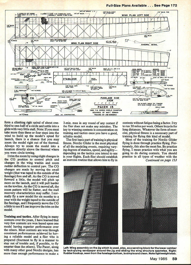
- Jig: Build the wing on a jig consisting of a 1-in. balsa plank, 6 in. wide, glued to the top of a straight hardwood plank. Draw the lower camber shape on one end of the balsa plank. Make a series of spanwise saw cuts about 1/8 in. apart in the top of the plank with the table saw; adjust the depth so each cut reaches the lower camber outline. Remove the balsa between cuts with a razor plane and sanding block down to the lower surface contour. The jig allows building and repairing wings while always maintaining the same lower-surface shape.
- Ribs: Cut wing ribs from three 1/16-in. sheets of the hardest balsa available. Cut sheets into 6-in. lengths, stack and tape them, and cut the rib shape slightly oversize on a band saw. Pin the required number of center-panel ribs together for sanding the lower camber using coarse sandpaper tacked to the wing jig. Do the same for tip ribs. Sand the upper surface of the rib stack with a flat sanding block. If too much material is removed in any area, Hot-Stuff a sheet of balsa to the top of the rib stack and continue sanding until the intended airfoil is achieved. Then cut away for the D-tube sheeting and lower spar and separate the ribs (cut apart with a sharp knife if material was added). The same technique yields very accurate, consistent airfoils for the tips.
- Leading edges: Build up the leading edges by Hot-Stuffing a 3/4-in. strip of carbon-fiber sheet down to the lower D-tube sheeting, then gluing on a second layer of carbon-fiber in the areas shown on the plans. Hot-Stuff the 3/8 x 1/4-in. leading-edge piece on top. Jim Bradley's carbon-fiber sheet material works well; cut with a sharp razor blade guided by a straightedge and glue down with Hot Stuff—quicker and easier than loose fibers and epoxy.
- Trailing edges: Cut trailing edges on a table saw from very hard blocks of balsa (pre-cut stock is often too soft). To remain warp-free, use the hardest wood available for ribs and trailing edges. After cutting to shape, use a Dremel Moto-Tool in a router setup to cut 3/16-in. slots for carbon-fiber, and glue carbon-fiber sheet material into the trailing edges with Hot Stuff.
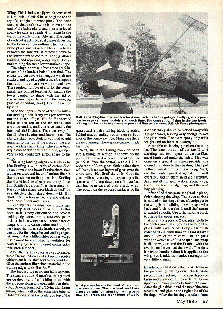
- Inboard top spars: Cut spars to shape, then pin them upside down on a flat building board with the aft edge along a straightedge. Install a 6-in. length of 3/16-in. aluminum tubing as the wing-wire tube: Hot-Stuff it across the center on top of the spars and add a balsa fairing block behind it extending out an inch on both ends of the tube. Ensure no openings allow epoxy to get inside the tube. Shape the fairing block into the triangular section shown on the plans. Wrap the center part of the spar (5 in. from the center) with a 1/2-in.-wide strip of 2-oz. glass cloth so there are at least two layers of glass over the entire tube; Hot Stuff the ends. Coat the glass with slow-curing epoxy and pin the spar assembly top down on a flat surface covered with plastic wrap. Blot excess epoxy so only enough remains to wet the glass cloth—extra epoxy only adds weight.
- Panel assembly: Assemble each wing panel on the wing jig. The inner portion of the top D-tube sheeting has two layers of carbon-fiber sheet laminated under the balsa; this was done on a special jig providing the correct curvature. Install the dihedral joints on the wing jig. Cut center-panel diagonal ribs oversize and fit carefully. Install spar vertical shear webs, spruce leading-edge cap, and root-bay planking. After gluing, finish shaping the wing: sand the lower surface by tacking sandpaper to the wing jig and sliding the wing spanwise; use a flat sanding block to shape the upper surface.
- Glassing: Apply two layers of 1/2-oz. glass cloth to the center-panel D-tubes with K&B Super Poxy clear finish reduced 50/50 with thinner (about 1 oz. of mixture). Cut the glass with the weave at 45° to the span and wrap it all the way around the D-tube with the overlap on the vertical shear web. The glass is hard to handle before application but adds tremendous strength for very little weight.
Fuselage
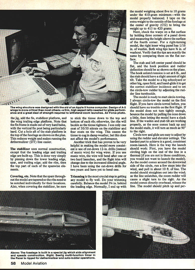
- Build the fuselage on a flat jig: lay down the left-side pieces, stack and glue the nose pieces of balsa and plywood, then glue on the tail-boom upper and lower pieces to finish the core. After glue dries, sand the top of the core and glue on the right side of the fuselage.
- After removing from the jig, add the fin, stabilizer platform, and wing trailing-edge platform. The fin frame is made of very hard balsa, especially the vertical fin post. Cut a hole aft of the stab platform in the top of the fuselage (as shown on the plan) to reduce weight and make running the dethermalizer (DT) line easier.
- Stabilizer: Use normal construction, except the leading edge and trailing edge are built up. Pin down the lower leading edge, spar, and trailing edge; add ribs, then the top parts of the spanwise elements.
Covering and hardware
- Spars are tapered throughout the model—ribs must be individually notched for their locations.
- When covering the stabilizer, stick the tissue down to the top and bottom of each rib; otherwise ribs will buckle as the tissue tightens. Use one coat of 50/50 nitrate on the stabilizer and four coats on the wing. This causes tissue to sag somewhat in damp weather, but performance is not affected.
- Wing wires: Use cut-down 12-in. drills (instead of music wire) for wing wires. Music wire will bend after a few hard launches and change flight trim due to increased dihedral. Cut-down drills have proven very durable.
Trimming
Trimming is the most crucial step in getting any model to fly well. Do trimming carefully.
- Balance: Balance the model 3/4 in. behind the leading edge. Normally the finished model ends up about 5–10 g under the 410-gram minimum with the model properly balanced. Tape extra weight to the outside of the fuselage at the center of gravity (CG) to bring the weight up to 415–420 g.
- Warps and wash: Check warps on a flat surface by holding three corners of a panel down and measuring the height of the fourth corner. For a right-turning model:
- Right inner wing panel: 1/16 in. of washin.
- Both wing tips: 3/8 in. of washout.
- Verify tips are identical by comparing them on the flat surface.
- The stab and left center panel should be flat.
- Hook and rudder: Set hook position and rudder deflection as shown on the plans. Hook unlatch tension is set at 6 lb. The stabilizer should have a slight right tilt. Hand-glide the model in a large open area to obtain correct stabilizer incidence and to set the circle-tow rudder by adjusting the rudder-line turnbuckle.
- Circle-tow: Always circle-tow on the first flight. If the model does not turn tightly enough, "bounce" the model by pulling the nose down a little and then letting the line go slack; if washin and stab tilt are correct, when the nose comes back up and the model stalls it can turn as much as 90° to the right.
- Launch/zoom technique: The zoom-launch is the hardest part to trim consistently. The launch should work as follows:
- Circle-tow the model high on the end of the line in a thermal.
- As the model comes around the downwind side of the circle, run a few steps into the wind and pull in about 10 ft. of line. The model should straighten into the wind; as the line unlatches, the zoom rudder will cause a slight right turn.
- As the model comes directly overhead, release the line. The model should pitch up and form a climbing right spiral of about one-third to one-half of a circle and then settle into a glide with very little stall.
Note: If you must take more than three or four steps into the wind to build speed, you may zoom the model out of the thermal. Always try to zoom the model into a location directly above the thermal where you were circle-towing.
- Fine-trim adjustments: Trim the zoom by:
- Slight CG changes to control pitch (move the small weight taped to the outside of the fuselage fore or aft).
- Adjusting wing washin and zoom-rudder deflection to control yaw.
Moving the CG forward causes the model to pitch up more on launch and pull harder on the towline. Moving the CG aft flattens the zoom pattern but may worsen stall recovery. The author typically flies a new model for six months to a year with the weight taped to the outside and frequently adjusts CG to improve trim.
Training and tactics
Winning contests usually depends less on having a single superior model and more on consistent performance from a reliable model and a prepared flier. The Pacer (and other good Nordic designs) has more than enough performance to make a 3-minute max in any round if the flier avoids mistakes. The key is training and tactics.
- Physical fitness: Nordic Glider is physically demanding—stamina, speed, and agility matter. Establish an exercise routine so fatigue won't be a factor. The author runs about 30 miles per week; others bicycle long distances. Whatever the method, fitness is required.
- Practice flying: Practice with the exact models and procedures you'll use in contests and in all types of weather. Practice with other modelers when possible—compare performances and learn model peculiarities. Know which models glide better, which turn tighter on tow, and choose the best model for the day's conditions.
- Contest tactics: Tactics depend on ability, model characteristics, weather, and contest size. Examples:
- Circle-towing downwind and piggybacking can work well at large contests when thermals are strong.
- In early morning light-air conditions, piggybacking often doesn't work because it's hard to tell which models are in good air without extended observation.
Watch successful fliers at each contest and try different tactics until you find what works for you in varying conditions.
- Competition experience: Fly in as many contests as you can. Develop model trim and tactics for all conditions. Don't be discouraged by a dropped max—use it as motivation to practice more, and practice under contest conditions.
Conclusion
The Pacer 15 represents a refined, contest-proven F1A design incorporating lightweight extremities, carbon-fiber and fiberglass reinforcement, and a glide-rudder delay for consistent zoom-climbs. With careful construction, meticulous trimming, disciplined practice, and sound tactics, the Pacer is a championship-capable model.
Transcribed from original scans by AI. Minor OCR errors may remain.

