
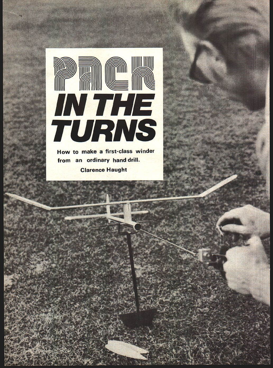
PACK IN THE TURNS
How to make a first-class winder from an ordinary hand drill.
Clarence Haught TO THE RUBBER-POWER modeler a good mechanical winder is an absolute necessity. Winders allow the rubber motor to be stretched out three or four times its normal relaxed length for winding, thus providing more turns (more duration), and reducing the initial power burst to a controllable level.
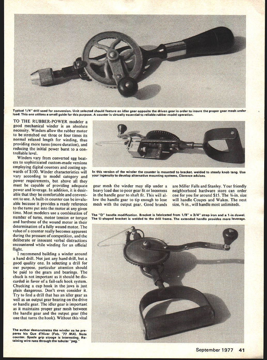
Winders vary from converted egg beaters to sophisticated custom-made versions employing digital counters and costing upwards of $100. Winder characteristics will vary according to model category and power requirements, but above all they must be capable of providing adequate power and leverage. In addition, it is desirable that they be comfortable and convenient to use. A built-in counter can be invaluable because it provides a ready reference to the turns put into the motor at any given time. Most modelers use a combination of number of turns, motor tension or torque and hardness of the wound motor in the determination of a fully wound motor. The value of a counter really becomes apparent during the pressure of competition, and the deliberate or innocent verbal distractions encountered while winding for an official flight.
I recommend building a winder around a hand drill. Not just any hand drill, but a good quality one. In selecting a drill for our purpose, particular attention should be paid to the gears and bearings. The chuck is not important as it should be discarded in favor of a fail-safe hook system. Chucking a cup hook in the jaws is just plain dangerous. Don't even consider it. Try to find a drill that has an idler gear as well as an output gear bearing on the drive or handle gear. The idler gear is important as it maintains proper gear mesh between the handle gear and the output gear (the one that turns the hook). Without this vital gear mesh the winder may slip under a heavy load due to poor gear fit or looseness in the handle gear to shaft fit. This will allow the handle gear to tip enough to lose mesh with the output gear. Good brands are Miller Falls and Stanley. Your friendly neighborhood hardware store can order one for you for around $15. The 1/4-in. size will handle Coupes and Wakes. The next size, 3/8-in., will handle most unlimiteds. Remove the chuck by screwing it off the threaded drill output shaft. Drill a hole through the shaft approximately 3/8 in. from the end to accept a music-wire winding hook similar to the one in the photos. The wire size of this hook should be one size larger than the prop shafts of the models you intend to use the winder on, but never smaller than the actual prop shaft size.
The hook formed must be centered with the winder output shaft when the right-angle bend of the hook is inserted in the winder. Retain the hook with a wheel collar with the set screw bearing in a small notch in the hook or with carefully hard-soldered washers.
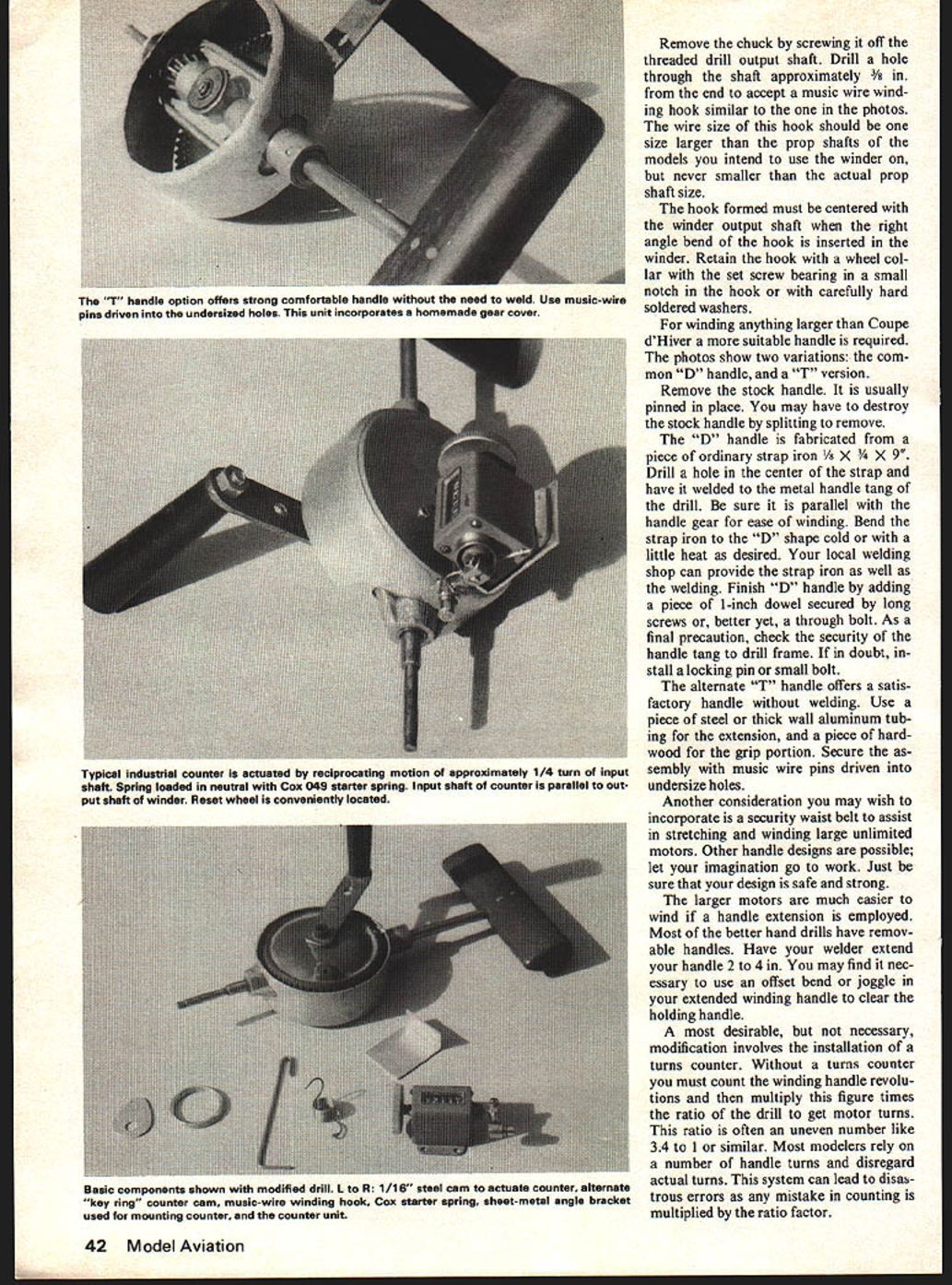
For winding anything larger than Coupe d'Hiver a more suitable handle is required. The photos show two variations: the common "D" handle, and a "T" version.
Remove the stock handle. It is usually pinned in place. You may have to destroy the stock handle by splitting to remove.
The "D" handle is fabricated from a piece of ordinary strap iron 1/8 x 3/4 x 9". Drill a hole in the center of the strap and have it welded to the metal handle tang of the drill. Be sure it is parallel with the handle gear for ease of winding. Bend the strap iron to the "D" shape cold or with a little heat as desired. Your local welding shop can provide the strap iron as well as the welding. Finish "D" handle by adding a piece of 1-inch dowel secured by long screws or, better yet, a through bolt. As a final precaution, check the security of the handle tang to drill frame. If in doubt, install a locking pin or small bolt.
The alternate "T" handle offers a satisfactory handle without welding. Use a piece of steel or thick-wall aluminum tubing for the extension, and a piece of hardwood for the grip portion. Secure the assembly with music-wire pins driven into undersize holes.
Another consideration you may wish to incorporate is a security waist belt to assist in stretching and winding large unlimited motors. Other handle designs are possible; let your imagination go to work. Just be sure that your design is safe and strong.
The larger motors are much easier to wind if a handle extension is employed. Most of the better hand drills have removable handles. Have your welder extend your handle 2 to 4 in. You may find it necessary to use an offset bend or joggle in your extended winding handle to clear the holding handle.
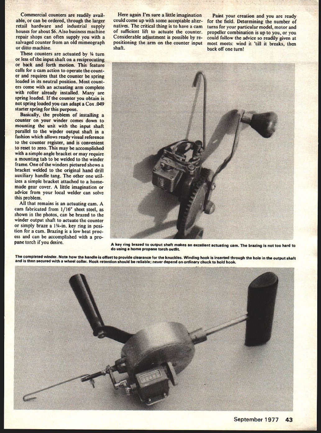
A most desirable, but not necessary, modification involves the installation of a turns counter. Without a turns counter you must count the winding handle revolutions and then multiply this figure times the ratio of the drill to get motor turns. This ratio is often an uneven number like 3.4 to 1 or similar. Most modelers rely on a number of handle turns and disregard actual turns. This system can lead to disastrous errors as any mistake in counting is multiplied by the ratio factor. Commercial counters are readily available, or can be ordered, through the larger retail hardware and industrial supply houses for about $6. Also business machine repair shops can often supply you with a salvaged counter from an old mimeograph or ditto machine.
These counters are actuated by 1/4 turn or less of the input shaft on a reciprocating or back and forth motion. This feature calls for a cam action to operate the counter and requires that the counter be spring loaded in its neutral position. Most counters come with an actuating arm complete with roller already installed. Many are spring loaded. If the counter you obtain is not spring loaded you can adapt a Cox .049 starter spring for this purpose.
Basically, the problem of installing a counter on your winder comes down to mounting the unit with the input shaft parallel to the winder output shaft in a fashion which allows ready visual reference to the counter register, and is convenient to reset to zero. This may be accomplished with a simple angle bracket or may require a mounting tab to be welded to the winder frame. One of the winders pictured shows a bracket welded to the original hand drill auxiliary handle tang. The other one utilizes a simple bracket attached to a homemade gear cover. A little imagination or advice from your local welder can solve this problem.
All that remains is an actuating cam. A cam fabricated from 1/16" sheet steel, as shown in the photos, can be brazed to the winder output shaft to actuate the counter or simply braze a 1-1/4-in. key ring in position for a cam. Brazing is a low heat process and can be accomplished with a propane torch if you desire.
Here again I'm sure a little imagination could come up with some acceptable alternatives. The critical thing is to have a cam of sufficient lift to actuate the counter. Considerable adjustment is possible by repositioning the arm on the counter input shaft.
Paint your creation and you are ready for the field. Determining the number of turns for your particular model, motor and propeller combination is up to you, or you could follow the advice so readily given at most meets: wind it 'till it breaks, then back off one turn!
Transcribed from original scans by AI. Minor OCR errors may remain.

