
Parakeet
Dave Robelen
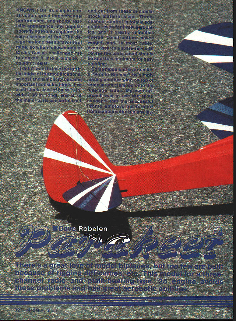
Introduction
Known for its simple construction, great three-channel performance, and sporty, realistic appearance, my sport-flying Pronto captures the very essence of fun. The Parakeet is a biplane conversion that keeps the Pronto's basic concepts while starting from scratch with a biplane layout. Cost and simplicity were important design considerations: most major parts can be laid out and cut from stock 3/16 in. x 36 in. balsa. Three-channel control (rudder, elevator, throttle) is totally adequate even for lively aerobatics, simplifies construction, saves weight and often allows a spare servo.
I patterned the fuselage and tail generally after home-built single-seat EAA-type biplanes, following the earlier Pronto concept whenever suitable. I used stock 3-in.-wide material and selected a tail‑dragger landing-gear setup because a nose‑wheel biplane looks wrong and has disadvantages for rough-field operation.
Design and flying characteristics
- Tail‑dragger advantages: operates from small bumpy fields, avoids grass drag, alignment problems and added weight associated with a nose wheel.
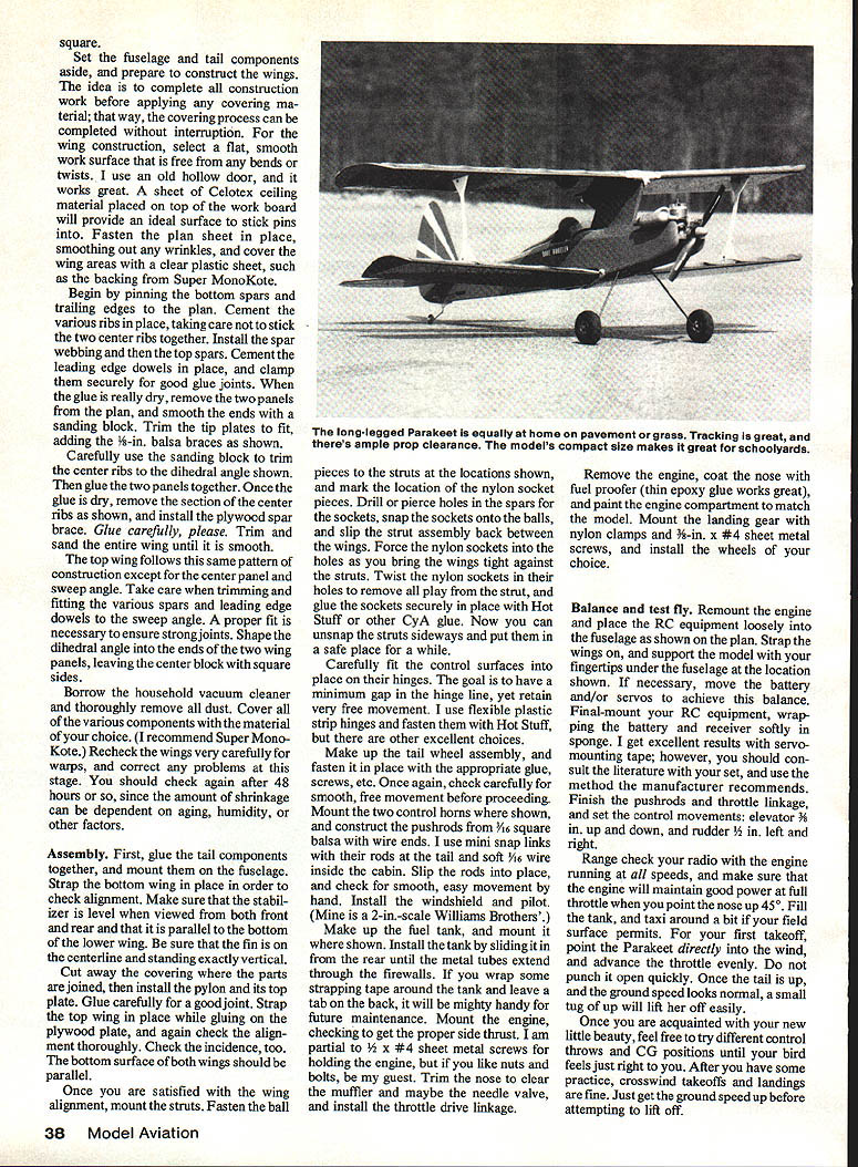
- Landing gear: wire V‑strut gear has proven excellent for tracking on takeoff, resists ground looping, is relatively light and damage resistant. Wheel position shown on the plans is a good average for both grass and paved runways. To fly off very bumpy strips or thick grass, bend the wheels forward about 1/8 in.
- Controls and tuning: start with modest control movements and the balance (CG) shown on the plans as a starting point. Most aggressive pilots will want more control and will likely move the balance point rearward to enhance snap‑roll maneuvers. Make changes one at a time and test at ample altitude (about “two mistakes high”).
Recommended power and prop
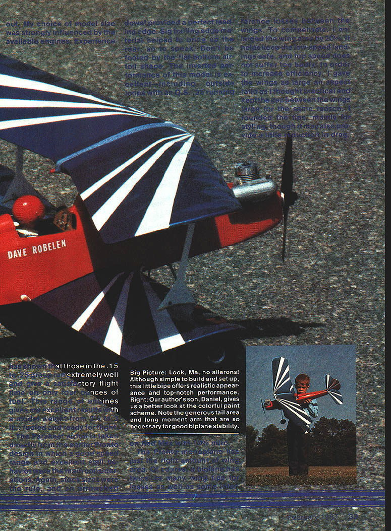
- Normal flying and moderate maneuvering: strong .15 (for example, Enya .15 IV).
- Strong aerobatics: .25-size engine (F.S.R.-type engines recommended).
- Propeller: Master Airscrew 9‑4 works well.
Wing setup
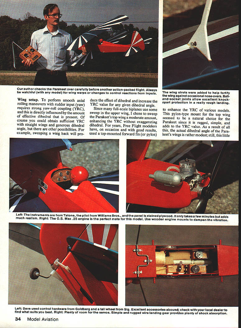
Yaw‑roll coupling (YRC) is critical for smooth axial rolling maneuvers using rudder input. YRC is influenced by effective dihedral. Rather than using large dihedral, the Parakeet uses a moderate sweep on the top wing (as many full‑scale biplanes do) to enhance YRC without exaggerating dihedral.
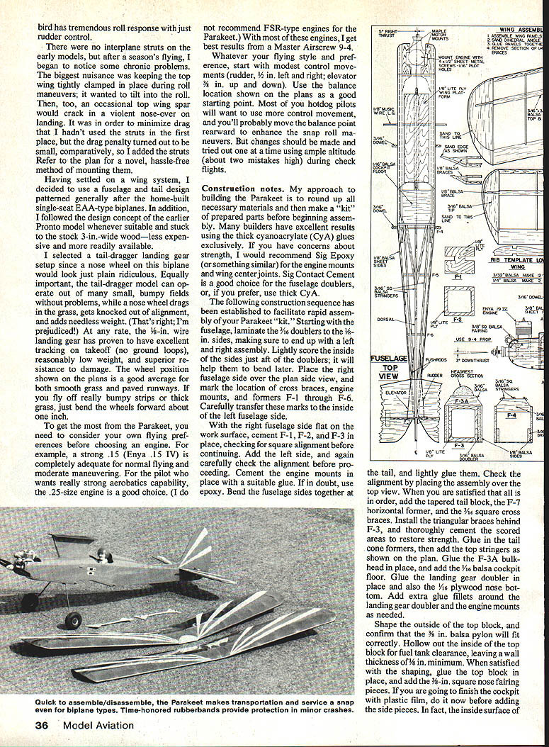
A pylon‑type mount for the top wing enhances YRC, is rugged and simple, and facilitates a modest dihedral angle while maintaining tremendous roll response with rudder control. Early models without interplane struts experienced top‑wing spar cracking during violent nose‑over landings; the small drag penalty from adding struts is outweighed by the added strength. Ball‑and‑socket joints provide knock‑apart protection for rough landings.
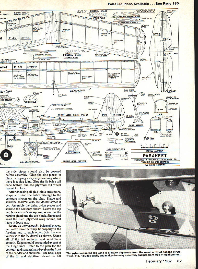
Refer to the plans for the mounting and strut arrangement.
Construction notes
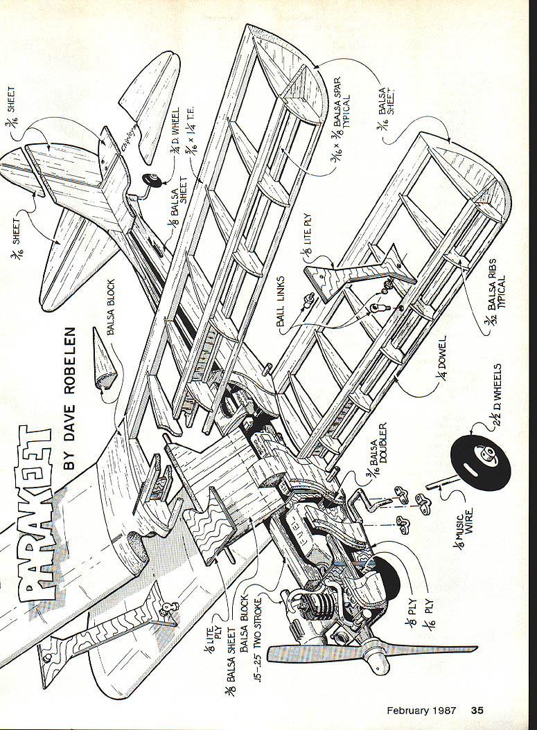
Materials and adhesives
- Stock sizes: 3/16 in. balsa and 3-in.-wide stock where noted on plans.
- Glues: many builders use thick cyanoacrylate (CyA) exclusively. For high‑stress areas such as engine mounts and wing‑center joints, use epoxy (for example, Sig Epoxy). Sig Contact Cement is useful for fuselage doublers. Hot Stuff or other CyA is suitable for gluing the nylon sockets for the struts.
- Covering: Super MonoKote is recommended.
Prepare all materials and make a “kit” of prepared parts before assembly.
Fuselage
- Laminate 3/16-in. doublers to the 1/8-in. fuselage sides, producing a left and right side. Lightly score the inside of the sides just aft of the doublers to aid later bending.
- Place the right fuselage side over the plan and mark cross braces, engine mounts, and formers F‑1 through F‑6. Transfer these marks to the inside of the left side.
- With the right side flat, cement F‑1, F‑2 and F‑3 in place, checking for square alignment. Add the left side and recheck alignment.
- Cement the engine mounts (use epoxy if in doubt). Bend fuselage sides together at the tail, glue lightly, and verify alignment with the top view on the plan.
- Add the tapered tail block, F‑7 horizontal former, and 3/16-in. square cross braces. Install triangular braces behind F‑3 and cement the scored areas to restore strength.
- Glue in tail cone formers, add top stringers, glue F‑3A bulkhead and 1/8-in. balsa cockpit floor. Glue landing gear doubler and 1/8-in. plywood nose bottom, adding extra glue fillets around these high‑stress areas.
- Shape the top block and confirm the 3/8-in. balsa pylon fit. Hollow out the top block for fuel tank clearance leaving at least 1/8-in. wall thickness. Glue the top block and add 3/8‑in. square nose fairing pieces.
- Cover inside surfaces of side pieces if finishing the cockpit with plastic film, then glue the side pieces in place, stripping away covering where glue joints are made. Glue the 1/16‑in. balsa tail cone bottom and plywood tail wheel mount.
- Shape and sand the fuselage and headrest (do not attach the headrest yet). Assemble and sand the balsa pylon pieces, leaving top and bottom surfaces square where they are glued into the top block. Shape and sand the 1/8‑in. plywood wing mount but leave it loose.
Tail surfaces
- Gather the 3/16‑in. balsa tail pieces and fit them to the fuselage. Join elevators with a 3/32‑in. dowel as shown on the plans.
- Shape and sand tail surfaces. Round edges except at hinge lines. Sand a sharp bevel on the front of the rudder and elevators; leave the back edges of fin and stabilizer square.
Wings
- Select a perfectly flat work surface (old hollow door with Celotex on top works well). Fasten the wing plan and cover with clear plastic to prevent sticking.
- Pin bottom spars and trailing edges to the plan. Cement ribs in place, taking care not to stick center ribs together.
- Install spar webbing, then top spars. Cement leading edge dowels and clamp securely.
- When dry, remove panels from plan and smooth ends. Trim tip plates and sand 1/8‑in. balsa braces as shown.
- Trim center ribs to dihedral angle, then glue panels together. Remove specified section of center ribs and install plywood spar brace.
- Top wing follows the same pattern but includes the sweep angle for YRC. Trim and fit spars and leading edge dowels to the sweep angle for a strong joint. Shape dihedral into panel ends, leaving the center block with square sides.
- Vacuum dust, then cover components (Super MonoKote recommended). Recheck wings for warps immediately and again after 48 hours to allow for covering shrinkage.
Assembly
- Glue tail components together and mount on the fuselage.
- Strap the bottom wing in place and check alignment. Ensure stabilizer is level (front and rear views), parallel to the lower wing, and that the fin is vertical and on the centerline.
- Cut away covering where parts join. Install the pylon and its top plate; glue carefully. Strap the top wing in place while gluing on the plywood plate and check alignment and incidence. The bottom surfaces of both wings should be parallel.
- Mount struts: fasten ball pieces to struts at locations shown, mark nylon socket locations, drill or pierce holes in spars for sockets, snap sockets onto the balls and slip strut assembly between wings. Force sockets into holes, twist to remove play, and glue sockets securely with CyA. Unsnap struts sideways for storage when finished.
- Fit control surfaces into hinges aiming for minimal hinge gap while retaining free movement. Flexible plastic strip hinges fastened with CyA work well.
- Make the tail wheel assembly and fasten it in place. Verify smooth free movement.
- Install control horns, make pushrods from 1/16-in. square balsa with wire ends (or preferred method). Use mini snap links at the tail and soft 1/16-in. wire inside the cabin if desired. Check for smooth movement by hand.
- Install windshield and pilot figure before final cockpit finishing.
- Make up the fuel tank, slide it in from the rear so metal tubes extend through the firewall, and secure with tape tabs for maintenance access.
- Mount the engine with appropriate side thrust. Sheet‑metal screws (1/2 x #4) are convenient; nuts and bolts are acceptable. Trim nose for muffler and needle valve clearance and install throttle linkage.
- Remove engine, coat the nose with fuel proofer (thin epoxy works well) and paint the engine compartment to match. Mount landing gear with nylon clamps and 5/8‑in. x #4 sheet‑metal screws and install wheels.
Balance and test flight
- Remount engine and place RC equipment loosely according to the plan. Strap wings on and support the model under the fuselage at the location shown to check balance. Move battery and/or servos as needed to achieve the correct CG.
- Final-mount RC equipment, wrapping battery and receiver in foam. Servo mounting tape works well; follow your radio manufacturer's recommendations.
- Finish pushrods and throttle linkage. Suggested initial control movements: start modestly (rudder about 1/2 in. left and right; elevator about 1/2 in. up and down). For final setup many builders use elevator 3/16 in. up and down and rudder 1/2 in. left and right—adjust as desired after initial flights.
- Range‑check the radio with the engine running at all speeds. Confirm the engine maintains full‑throttle power before first takeoff.
- Taxi the model if field conditions permit. For first takeoff, point the Parakeet directly into the wind and advance throttle evenly. Do not pivot quickly on the ground. Once the tail is up and ground speed is normal, a small elevator push will lift off easily.
- Fly conservatively on early flights. Use ample altitude for testing—about “two mistakes high.” Make one change at a time (trim, control throws, CG) and evaluate before further adjustments.
- After you are acquainted with the Parakeet, feel free to try different control throws and CG positions until the model suits your flying style. Crosswind takeoffs and landings are fine once you have practice; ensure adequate ground speed before attempting to lift off.
Notes and tips
- Ball‑and‑socket joints and a pylon mount help protect the wing in rough landings.
- Keep parts count and complexity low to simplify building and reduce weight.
- Check all glue joints, sand surfaces smoothly, and verify alignment repeatedly during assembly.
- Recheck wings for warps after covering shrinkage has settled (about 48 hours).
Happy building and safe flying.
Transcribed from original scans by AI. Minor OCR errors may remain.

