
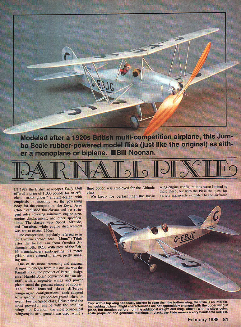
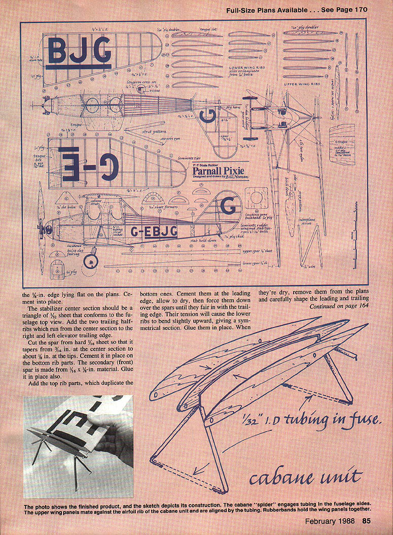
Parnall Pixie
In 1923 the British newspaper Daily Mail offered a prize of 1,000 pounds for an efficient "motor glider" aircraft design, with emphasis on economy. As the governing body for the competition, the Royal Aero Club established the classes and set stringent rules covering minimum engine size, engine displacement, and other specifications. The classes were:
- Speed
- Altitude
- Duration
Engine displacement was not to exceed 750 cc.
The competition, popularly referred to as the Lympne (pronounced "Limm") Trials after the locale, ran from October 8 through 13, 1923. With most of the British manufacturers participating, 21 motor gliders were entered in all — a remarkable total.
One of the more interesting and unusual designs to emerge from this contest was the Parnall Pixie, the product of Parnall design chief Harold Bolas' conviction that an aircraft with changeable wings and power plants stood the greatest chance of success. The Pixie featured three different wing/engine configurations, each adapted to a specific Lympne class or event. For the Speed class, Bolas paired the most powerful engine with the smallest wings; for Duration, the most economical wing/engine arrangement was used; while a third option was employed for the Altitude class.
We know for certain that the basic wing/engine configurations were limited to these three, but with the Pixie the quest for variety apparently extended to the airframe as well. Documentation as to the exact number of different airframes produced remains unclear; it's hard to pinpoint what constituted a specific variant among the assorted mutations that came along.
All of the Lympne contenders were hampered by a lack of reliable power plants — a frequent complaint in the 1920s — and the Pixie was no exception. Its problems with clogged fuel lines and recalcitrant magnetos limited the diminutive craft to a single notable victory. In the Speed event, the Pixie's 76.1 mph average bested entries from de Havilland, Avro, Hawker, and Handley Page.
After the 1923 Lympne competition, the Pixie was flown as a sport aircraft, registered G-EBJG, and finally assigned to the Aeroplane and Armament Experimental Establishment to be evaluated by service pilots as a trainer. The pilots' unanimous verdict was that although it was generally well suited as a trainer, the airplane afforded inadequate downward vision over the wing.
For its last fling in competition the Pixie returned to Lympne, where the famed Frank Courtney flew it to fourth place in the September 1926 Air Ministry Trials.
The G-EBJG example did survive World War II and was presented to the Midland Aircraft Preservation Society by its fifth owner. Whether it exists today is not known.
Construction
Before starting construction, take time to study the plans and familiarize yourself with details such as wood sizes and how individual components fit together.
Fuselage
- Cover the plans with wax paper or Saran Wrap before construction to protect them from surplus glue.
- Note that longerons are laminated from 1/16-sq. and 1/8 x 1/32 balsa. Refer to a typical cross-section detail on the plans. Although this is a bit more trouble than conventional square timber, it results in a much neater covering since the tissue does not adhere to the upright structure except at each end of the fuselage.
- After laying the longerons in place, fit in all upright 1/16-sq. parts. The rubber anchor provision at the rear is faced with 1/4-ply wood for extra strength.
- The longeron configuration allows for a 1/32-in. step, permitting you to set the 1/32-sheet balsa into the nose sides. This also applies to the plate which the wing root abuts.
Make a right side and a left side, then cement them together at the tail post, making sure that the 1/32-edge longeron component faces out. Cement in the cross braces at their appropriate stations, starting in the cockpit area. Pin the nose last; consult the top view for width.
Cut former B from 1/20 medium balsa sheet and cement in place. Follow the same procedure with the rest of the formers, confirming their width by taking measurements off the fuselage as it tapers toward the tail post. Mark off and file stringer notches aft from former D; a folded piece of 200-grit sandpaper or a small jeweler's file will facilitate this. The forward formers have only one stringer running along the center. These are covered with straight-grained 1/32-sheet balsa.
Rough-cut the nose block from medium balsa, tack it in place temporarily with a dab of cement, and finish contouring it to fair in with the fuselage frame lines. When satisfied with the fit, cement it in place. Shape, remove it, and cut it at station A, which separates the thrust button and dummy engine portion from the "skirt" immediately behind.
Cement the hollowed-out portion in place on the front of the fuselage frame. Cut former A (this has a rectangular cutout which will eventually receive the 1/16-in. indexing plug) from 1/16-sheet plywood, and cement it in place on the "skirt."
Removable wing option If you want removable wings for ease of storage and transit and to reduce breakage, incorporate the optional "tongue-and-box" feature. Build the tongues following the pattern on the plans. Make a right and a left tongue by cutting two pieces of laminated material fashioned by cementing 1/4 plywood to 1/16-sheet balsa. Cut slots in the appropriate places to allow passage of the tongues past the uprights on the fuselage sides. Do not cement the tongues in place until you have completed the wings. Slide the tongues into the wing boxes to confirm proper incidence and dihedral before cementing them.
Landing gear
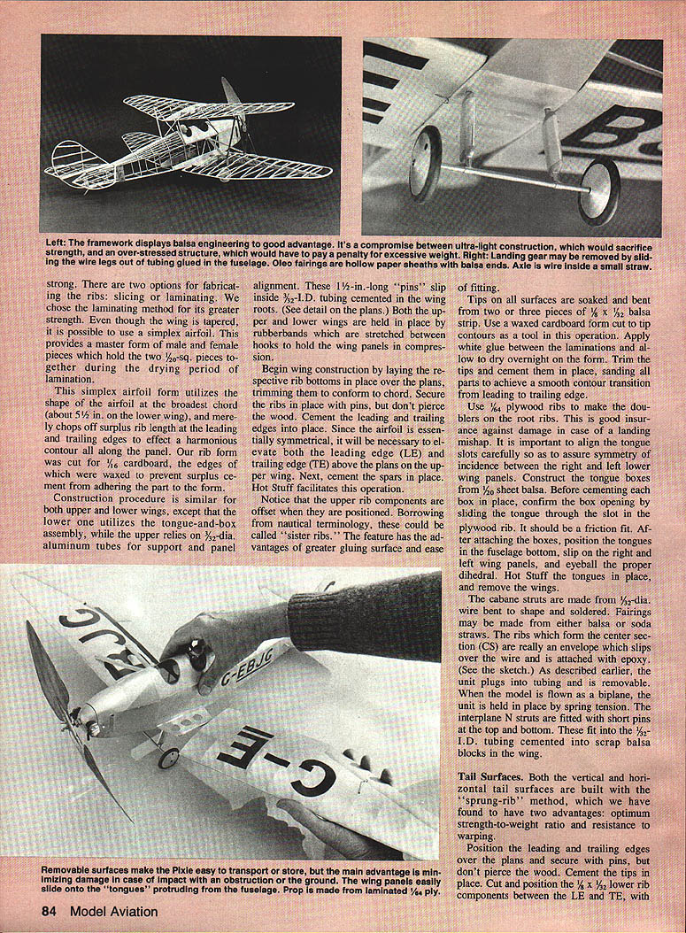
- The unusual landing gear is easy to install. The parallel single support struts are bent from 3/32-in. diameter wire and are sheathed with simulated oleo fairings made from light balsa.
- The spreader is soldered to the bottom of these and uses a small-diameter plastic straw to bring it up to scale appearance and to hide the solder joints.
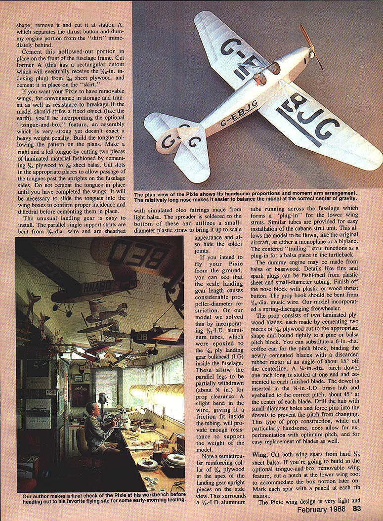
- If you intend to fly from the ground, the scale landing gear length causes considerable propeller-diameter restriction. One solution is to incorporate 1/32-in. I.D. aluminum tubes epoxied to the 1/8-ply landing gear bulkhead inside the fuselage. These allow the parallel legs to be partially withdrawn (about 3/8 in.) for prop clearance. A slight bend in the wire gives a friction fit inside the tubing and provides enough resistance to support the weight of the model.
- Note a semicircular reinforcing collar of 1/16 plywood at the apex of the landing gear upright pieces on the side view. This surrounds a 1/8-in. I.D. aluminum tube running across the fuselage which forms a "plug-in" for the lower wing struts. Similar tubes are provided for easy installation of the cabane strut unit.
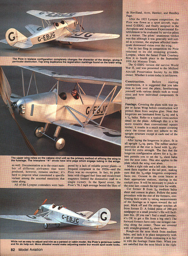
This allows the model to be flown, like the original aircraft, as either a monoplane or a biplane. The centered "trailing" strut functions as a plug-in for a balsa piece in the turtleback.
Dummy engine, propeller, and drive
- The dummy engine may be made from balsa or basswood. Details like fins and spark plugs can be fashioned from plastic sheet and small-diameter tubing. Finish off the nose block with a plastic or wood thrust button.
- The prop hook should be bent from 1/16-in. music wire. The model incorporated a spring-disengaging freewheeler.
- The prop consists of two laminated plywood blades, each made by cementing two pieces of 1/8 plywood together and shaping to the proper outline. Seal the prop with several coats of clear dope.
- You can substitute a 6-in.-dia. newly cemented blade set with a discarded rubber motor at an angle of about 15° off the centerline. A 1/8-in.-dia. birch dowel one inch long is slotted at one end and cemented to each finished blade. The dowel is inserted in the 1/8-in. I.D. brass hub and eyeballed to the correct pitch, about 45° at the center of each blade. Drill the hub with small-diameter holes and force pins into the dowels to prevent pitch change. This prop construction, while not particularly handsome, allows experimentation with optimum pitch and easy replacement of blades.
Wing
Cut both wing spars from hard 1/4-sheet balsa. If building the optional tongue-and-box removable wing feature, cut a notch at the lower wing root to accommodate the box portion later on. Mark each spar with a pencil at each rib station. The Pixie wing design is very light and strong.
There are two options for fabricating the ribs: slicing or laminating. The laminating method offers greater strength. Even though the wing is tapered, it is possible to use a simplex airfoil. This provides a master form of male and female pieces which hold the two 1/32-in. pieces together during the drying period of lamination.
This simplex airfoil form utilizes the shape of the airfoil at the broadest chord (about 5-1/2 in. on the lower wing) and merely chops off surplus rib length at the leading and trailing edges to effect a harmonious contour along the panel. The rib form was cut for 1/16 cardboard, the edges of which were waxed to prevent surplus cement from adhering the part to the form.
Construction procedure is similar for both upper and lower wings, except the lower wing utilizes the tongue-and-box assembly while the upper relies on 3/32-in.-dia. aluminum tubes for support and panel alignment. These 1-1/2-in.-long "pins" slip inside 3/32-in. I.D. tubing cemented in the wing roots. Both the upper and lower wings are held in place by rubber bands stretched between hooks to hold the wing panels in compression.
Begin wing construction by laying the respective rib bottoms in place over the plans, trimming them to conform to chord. Secure the ribs in place with pins, but don't pierce the wood. Cement the leading and trailing edges into place. Since the airfoil is essentially symmetrical, it will be necessary to elevate both the leading edge (LE) and trailing edge (TE) above the plans on the upper wing. Next, cement the spars in place. Hot Stuff (cyanoacrylate) facilitates this operation.
Notice that the upper rib components are offset when positioned; these "sister ribs" provide greater gluing surface and ease of fitting.
Tips on all surfaces are soaked and bent from two or three pieces of 1/8 x 3/4 balsa strip. Use a waxed cardboard form cut to tip contours as a tool. Apply white glue between the laminations and allow to dry overnight before trimming and cementing them in place. Sand all parts to achieve a smooth contour transition from leading to trailing edge.
Use 1/64 plywood ribs to make the doublers on the root ribs for damage protection. Align the tongue slots carefully to assure symmetry of incidence between the right and left lower wing panels. Construct the tongue boxes from 1/8-sheet balsa. Before cementing each box in place, confirm the box opening by sliding the tongue through the slot in the plywood rib; it should be a friction fit. After attaching the boxes, position the tongues in the fuselage bottom, slip on the right and left wing panels, and eyeball the proper dihedral. Hot-stuff the tongues in place, then remove the wings.
The cabane struts are made from 1/16-in.-dia. wire bent to shape and soldered. Fairings may be made from either balsa or soda straws. The ribs that form the center section (CS) are really an envelope which slips over the wire and is attached with epoxy. As described earlier, the unit plugs into tubing and is removable. When the model is flown as a biplane, the unit is held in place by spring tension. The interplane N struts are fitted with short pins at the top and bottom; these fit into 3/32-in. I.D. tubing cemented into scrap balsa blocks in the wing.
Tail Surfaces
Both the vertical and horizontal tail surfaces are built with the "sprung-rib" method, which has two advantages: optimum strength-to-weight ratio and resistance to warping.
- Position the leading and trailing edges over the plans and secure with pins, but don't pierce the wood.
- Cement the tips in place.
- Cut and position the 1/8 x 1/32-in. lower rib components between the LE and TE, with a 1/8-in.-sq rib at the center of each panel and 1/32-in.-sq stringers at 1/8-in. intervals to form the proper airfoil section. Cement these to the leading and trailing edges, then apply the top sheeting.
After covering and finishing the vertical stabilizer, cement the stabilizer to the fuselage centerline. Two .020-in. wire hooks are cemented in place at the bottom of the stabilizer. The tail unit will be secured to the top longerons by stretching small rubber bands through apertures in the fuselage bottom and attaching to the wire hooks. Short lengths of bamboo prevent the rubber bands from pulling back into the fuselage. This arrangement allows easy removal of the tail for transit or storage and also facilitates incidence changes, important during trimming and adjustment.
A final brace between the fin and stabilizer can be made of one continuous piece of 2-lb.-test nylon fishing leader, stitched through the stubs with a fine needle. The control wires which exit the fuselage turtleback at former G are fine elastic thread cemented in place. Loops at the trailing end engage notches in the 1/4-in. plywood control horn in the rudder, allowing unfettered removal of the tail.
Odds and ends
Cover the model with white Japanese tissue. Shrink it with a light spray application of rubbing alcohol. After drying, remove unsightly wrinkles by lightly sanding corners and edges with 400-grit wet-or-dry paper. Finish with three coats of clear nitrate dope reduced 50% with thinner for spraying consistency. In the last coat, silver powder was added at a ratio of about 1/2 teaspoon to an ounce of dope.
For registration letters you can use photographic transfers or cut black tissue carefully and cement it in place. Adhesive spray, available at artists' supply houses, facilitates application. Separation lines for ailerons, elevator, and rudder may be made either by carefully inked lines, 1/32-in. black Chartpak tape, or by airbrushed masking tape giving the illusion of contouring the typical leading portions of the respective surfaces.
The pilot was carved from light balsa, sanded and given a wood-filler bath. Acrylic colors were used to simulate skin and leather. Goggles were bent from small-diameter wire and carefully dipped in clear dope; capillary action of the dope closed the elliptical openings, forming lenses. This is easier than trying to fit small chunks of acetate.
Flying wires form diagonal bracing with the cabane unit as shown in the sketch.
Flight testing and trim
- We tested the model over tall grass on a windless morning. You don't need to copy the morning part, but it's prudent to have tall grass and calm conditions if possible.
- Start testing in the biplane configuration, but try the low-wing option early. The model can be touchy about exact center of gravity—if it's too far back you may have problems. Ours required careful stabilizer incidence changes in small (1/64-in.) increments at the leading edge. If you go too far, the model tends to dive into the ground. It should circle to the left when properly adjusted. The symmetrical-section top wing does not alter the adjustments if it is warp-free.
Power and rubber motor
- Power came from 12 strands (six loops) of 1/8-in. Sig rubber, about twice the length of the distance from the rear peg to the prop hook. You should be able to pack in about 1,000 turns.
- We recommend using a winding tube when pushing the rubber motor to the max.
The Parnall Pixie is unquestionably unique looking in its biplane mode and might be called handsome as a low-wing. Either way, it makes an interesting and rewarding project.
Transcribed from original scans by AI. Minor OCR errors may remain.

