
Part 2: How to Make High-Performance Props
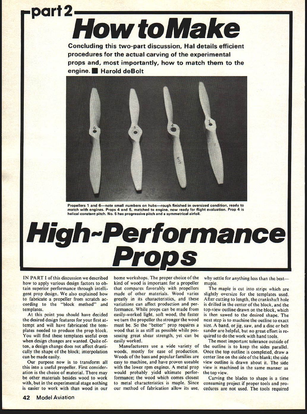
Concluding this two-part discussion, Hal details efficient procedures for the actual carving of the experimental props and, most importantly, how to match them to the engine. Harold deBolt
IN PART I of this discussion we described how to apply various design factors to obtain superior performance through intelligent prop design. We also explained how to fabricate a propeller from scratch according to the "block method" and templates.
At this point you should have decided the desired design features for your first attempt and will have fabricated the templates needed to produce the prop block. You will find these templates useful even when design changes are wanted. Quite often, a design change does not affect drastically the shape of the block; interpolation can be made easily.
Our purpose now is to transform all this into a useful propeller. First consideration is the choice of material. There may be other materials besides wood to work with, but in the experimental stage nothing is easier to work with than wood in our home workshops. The proper choice of the kind of wood is important for a propeller that compares favorably with propellers made of other materials. Wood varies greatly in its characteristics, and these variations can affect production and performance. While props can be made from easily-worked light, soft wood, the faster we turn the propeller the stronger the wood must be. So the "better" prop requires a wood that is as stiff as possible while possessing great shear strength, yet can be easily worked.
Manufacturers use a wide variety of woods, mostly for ease of production. Woods of the bass and poplar families are easy to machine, and have proven useable with the lower rpm engines. A metal prop would probably yield ultimate performance; the wood which comes closest to metal characteristics is maple. Since our method of fabrication allows its use, why settle for anything less than the best — maple.
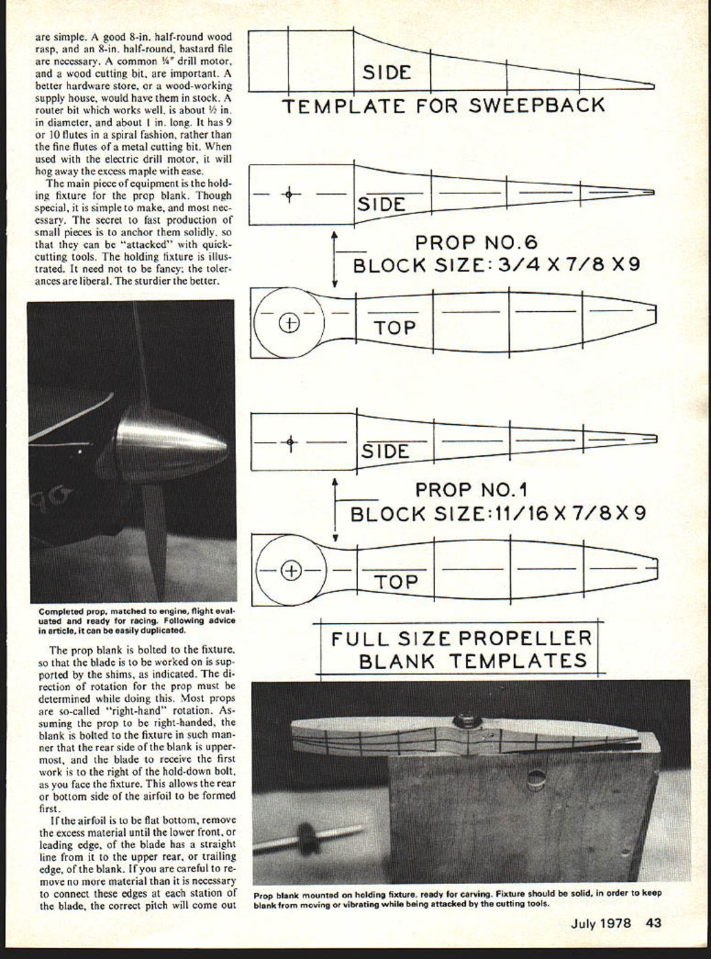
The maple is cut into strips which are slightly oversize for the templates used. After cutting to length, the crankshaft hole is drilled in the center of the block, and the top-view outline drawn on the block, which is then sawed to the desired shape. The next step is to machine the outline to exact size. A band or jig saw, and a disc or belt sander are helpful, but no great effort is required to do the work with hand tools.
The most important tolerance outside of the outline is to keep the sides parallel. Once the top outline is completed, draw a center line on the side of the blank; the side view outline is drawn about it. The side view is machined in the same manner as the top view.
Carving the blades to shape is a time consuming project if proper tools and procedures are not used. The tools required are simple. A good 8-in. half-round wood rasp, and an 8-in. half-round, bastard file are necessary. A common 1/4" drill motor, and a wood cutting bit, are important. A better hardware store, or a wood-working supply house, would have them in stock. A router bit which works well, is about 1/2 in. in diameter, and about 1 in. long. It has 9 or 10 flutes in a spiral fashion, rather than the fine flutes of a metal cutting bit. When used with the electric drill motor, it will hog away the excess maple with ease.
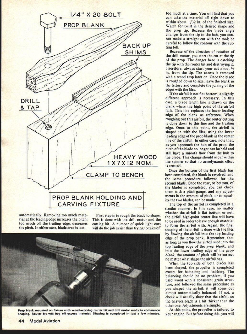
The main piece of equipment is the holding fixture for the prop blank. Though special, it is simple to make, and most necessary. The secret to fast production of small pieces is to anchor them solidly, so that they can be "attacked" with quick-cutting tools. The holding fixture is illustrated. It need not be fancy; the tolerances are liberal. The sturdier the better.
The prop blank is bolted to the fixture, so that the blade to be worked on is supported by the shims, as indicated. The direction of rotation for the prop must be determined while doing this. Most props are so-called "right-hand" rotation. Assuming the prop to be right-handed, the blank is bolted to the fixture in such manner that the rear side of the blank is uppermost, and the blade to receive the first work is to the right of the hold-down bolt, as you face the fixture. This allows the rear or bottom side of the airfoil to be formed first.
If the airfoil is to be flat bottom, remove the excess material until the lower front, or leading edge, of the blade has a straight line from it to the upper rear, or trailing edge, of the blank. If you are careful to remove no more material than is necessary to connect these edges at each station of the blade, the correct pitch will come out automatically. Removing too much material at the leading edge increases the pitch; too much off the trailing edge decreases the pitch. In either case, blade area is lost.
First step is to rough the blade to shape. This is done with the drill motor and the cutting bit. A number of quick light cuts will do the job easier than trying to take off too much at a time. You will find that you can take the material off right down to within about 1/32 in. of the finished size. Watch for twist in the desired shape and the prop tip. Because the blade angle changes from the tip to the hub, you cannot make a straight cut with the tool; be careful to follow the contour with the cutting tool.
Because of the direction of rotation of the drill motor, you start the cut at the tip of the prop. The danger here is catching the tip with the router bit and destroying it. Therefore, always start your cut about 1/8 in. from the tip. The excess is removed with a wood rasp later on. Once the blade is roughed down to size, leave the blank in the fixture and complete the joining of the edges with the files.
If the airfoil is not flat bottom, a slightly different approach is necessary. In this case, a blade length line is drawn on the blank where the high point of the airfoil falls. This line replaces the lower leading edge of the blank as reference. When roughing out this airfoil, the router cutting is done down to this line and the trailing edge. Once to this point, the airfoil is shaped in with the files, using the lower leading edge of the prop blank as the center line of the airfoil. In either case, note that, as you approach the hub of the prop, the pitch of the blade no longer can be held and still have a smooth flow from the hub to the blade. This change should occur within the spinner so that no aerodynamic effect is created.
Once the bottom of the first blade has been completed, the blank is revolved, and the same procedure followed for the second blade. Once the rear, or bottom, of the blades is completed, you can check them with a pitch gauge, and any adjustments in the amount of pitch, or to equalize the two blades, can be made.
The top of the airfoil is completed in a similar manner. In this case, no matter whether the airfoil is flat bottom or not, the airfoil high-point center line will have to be used in order to have enough material to form the airfoil with. Again, the final shaping of the airfoil is done with the files by flowing the airfoil into the top leading edge of the prop blank. Remember, that as long as you flow the airfoil used into the top leading edge of the prop blank, and into the lower trailing edge of the prop blank, the amount of pitch will be correct no matter what shape the airfoil has.
When the top side of both blades has been shaped, the propeller is completed except for balancing and finishing. The balancing should be no problem, if you used wood with a consistent grain structure, and followed the same procedure as you shaped the airfoil; it will come out almost automatically balanced. If not, a check will usually show that the airfoil on the heavier blade is a bit thicker than the other one. Adjustments are simple.
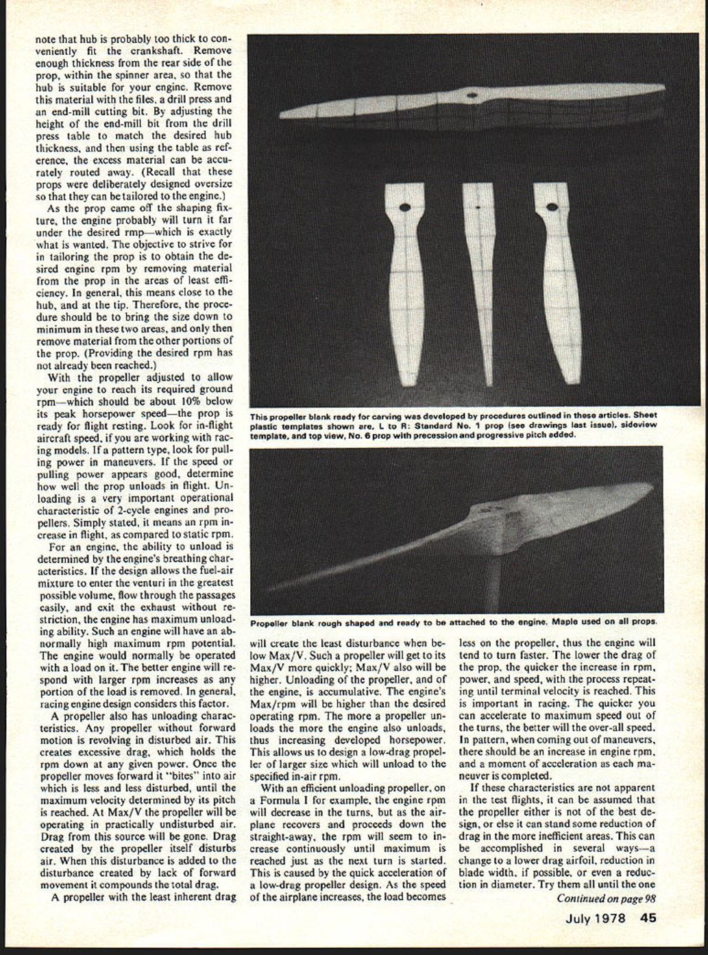
At this point, the propeller is tailored to your engine. But before doing this, you will note that hub is probably too thick to conveniently fit the crankshaft. Remove enough thickness from the rear side of the prop, within the spinner area, so that the hub is suitable for your engine. Remove this material with the files, a drill press and an end-mill cutting bit. By adjusting the height of the end-mill bit from the drill press table to match the desired hub thickness, and then using the table as reference, the excess material can be accurately routed away. (Recall that these props were deliberately designed oversize so that they can be tailored to the engine.)
As the prop came off the shaping fixture, the engine probably will turn it far under the desired rpm — which is exactly what is wanted. The objective to strive for in tailoring the prop is to obtain the desired engine rpm by removing material from the prop in the areas of least efficiency. In general, this means close to the hub, and at the tip. Therefore, the procedure should be to bring the size down to minimum in these two areas, and only then remove material from the other portions of the prop. (Providing the desired rpm has not already been reached.)
With the propeller adjusted to allow your engine to reach its required ground rpm — which should be about 10% below its peak horsepower speed — the prop is ready for flight testing. Look for in-flight aircraft speed, if you are working with racing models. If a pattern type, look for pulling power in maneuvers. If the speed or pulling power appears good, determine how well the prop unloads in flight. Unloading is a very important operational characteristic of 2-cycle engines and propellers. Simply stated, it means an rpm increase in flight, as compared to static rpm.
For an engine, the ability to unload is determined by the engine's breathing characteristics. If the design allows the fuel-air mixture to enter the venturi in the greatest possible volume, flow through the passages easily, and exit the exhaust without restriction, the engine has maximum unloading ability. Such an engine will have an abnormally high maximum rpm potential. The engine would normally be operated with a load on it. The better engine will respond with larger rpm increases as any portion of the load is removed. In general, racing engine design considers this factor.
A propeller also has unloading characteristics. Any propeller without forward motion is revolving in disturbed air. This creates excessive drag, which holds the rpm down at any given power. Once the propeller moves forward it "bites" into air which is less and less disturbed, until the maximum velocity determined by its pitch is reached. At Max V the propeller will be operating in practically undisturbed air. Drag from this source will be gone. Drag created by the propeller itself disturbs air. When this disturbance is added to the disturbance created by lack of forward movement it compounds the total drag.
A propeller with the least inherent drag will create the least disturbance when below Max V. Such a propeller will get to its Max V more quickly; Max V also will be higher. Unloading of the propeller, and of the engine, is accumulative. The engine's Max rpm will be higher than the desired operating rpm. The more a propeller unloads the more the engine also unloads, thus increasing developed horsepower. This allows us to design a low-drag propeller of larger size which will unload to the specified in-air rpm.
With an efficient unloading propeller, on a Formula I for example, the engine rpm will decrease in the turns, but as the airplane recovers and proceeds down the straight-away, the rpm will seem to increase continuously until maximum rpm is reached just as the next turn is started. This is caused by the quick acceleration of a low-drag propeller design. As the speed of the airplane increases, the load becomes less on the propeller, thus the engine will tend to turn faster. The lower the drag of the prop, the quicker the increase in rpm, power, and speed, with the process repeating until terminal velocity is reached. This is important in racing. The quicker you can accelerate to maximum speed out of the turns, the better will the over-all speed. In pattern, when coming out of maneuvers, there should be an increase in engine rpm, and a moment of acceleration as each maneuver is completed.
If these characteristics are not apparent in the test flights, it can be assumed that the propeller either is not of the best design, or else it can stand some reduction of drag in the more inefficient areas. This can be accomplished in several ways — a change to a lower drag airfoil, reduction in blade width, if possible, or even a reduction in diameter. Try them all until the one
How to Make Props/deBolt continued from page 45
with the greatest benefit is found.
The final step is to apply a finish, and to record exact blade shape so that duplicates can be made without further testing. At the high speeds which these blades travel, surface friction can create considerable drag. The reduction of this surface drag can add just as much to the performance, as can a reduction in drag by some design improvement. A good finish is important. You can finish a prop in any of the normal ways, using paints or epoxies. They are excellent. However, they require time to apply and should any changes be desired in the prop later on, much work is involved in replacing the finish.
A simple, and effective, prop finish is nothing more than wax. The propeller is smoothly finished with fine sandpaper, then paste wax (Simonize, Blue Coral, etc.) is rubbed into the wood. When the wax had dried, it is buffed with a cloth to a high lustre. An advantage, other than time saving, is that the prop can be altered at will and the finish quickly and easily replaced using the same method.
If your first custom prop gives you the desired results, you can easily duplicate the second time around. If you believe even better results can be had, experiment with the various design parameters, and note the results obtained. Keep simple records of the results. You will soon have some solid facts on which to base further experiments.
Since this writing, additional interesting results have become available. We spoke of prop unloading and its benefit. The nature of this benefit can be made clear by a comparison. If two props are identical in size and one unloads more, the latter allows the engine rpm to increase more, because we operate the engine below its maximum rpm. Any increase in rpm result in additional horsepower that can be used to turn a larger prop and to bring the engine back down to its Max/hp/rpm. The prop that unloads more is obviously adding more to the aircraft's efficiency. If two propellers are identical in size, and one unloads more than the other, it can only be because the propeller which reaches the higher rpm has less drag. Our present work aims towards removing drag from propellers. It is felt that drag controls the unloading ability to a great extent.
When we work with the unloading of engines and props we are in the area of greatest potential for improved performance. Both the horsepower curve of the engine and the thrust curve of the prop rise steeply as the maximum is approached. Any increase in rpm at the top end can be equal to many times as much rpm near the low end. Also, it should be considered that a few mph increase in the midspeed range means nothing, but added to what was the top, it becomes very important.
The results of my current work are these: I had an excellent-size normal propeller for Formula 1. From scratch, I produced a similar size, but lower drag, propeller using the ideas in this article. Most "normal" props will unload about 10% in the air. If the rpm is 20K on the ground you can expect 22K in the air. The new, lower-drag prop showed a 25% pick up, a decided increase. On the race course, this amounted to nearly 10 seconds! As can be seen, this 15% increase put the rpm at terminal velocity over the Max/hp/rpm for the engine. At this point, weather curtailed flight testing until the 1978 season. However, larger props already fabricated appear to have good potential in bench tests. Only flight will offer proof, of course.
The question is, do we increase the prop area, and if so, by diameter or blade width? Perhaps increasing pitch, or a combination of pitch and area, would prove best. Some interesting experiments appear in order.
It is suggested that the reader refer to Mr. deBolt's article "Better Props for Formula I" published in the May 1977 issue.
Transcribed from original scans by AI. Minor OCR errors may remain.

