
Part One Snipe: The Motivation
"YOU'RE CRAZY!" that's what my wife said. My friends asked, "Why on earth would you want to do that?" Even my aviation friends questioned, "What's your point? Why would you want to build your own airplane when you can buy one already built?"
This, however, was no mere whim. After all, I had been dreaming about and planning for this for 15 years. All my life I had been designing and building model aircraft. Now seemed like the appropriate time to build the real thing.
I know how much effort is involved. When I was a teenager I built a hot rod. Although I had very little money at the time, I made and scrounged parts to the point where I had a vehicle that was roadworthy and performed quite well. I also know what type of time commitment I am getting myself into. I know it will take thousands of hours just to design the airplane and many more hours to build and test it.
I will not comment on my wife's remarks, but to answer the question of why I want to build my own airplane, I offer the following justification:
- Challenge. I want to prove to myself and others that I have the skill and fortitude to accomplish such a formidable project.
- Utility. Rather than rent an aircraft whenever I want to fly, it would be convenient and economical to own and maintain my own.
- Financial benefit. If I design this aircraft properly, there is potential for plan sales to other home-builders.
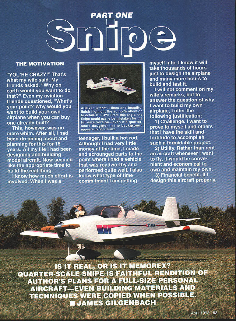
Caption: Is it real, or is it Memorex? Quarter-scale Snipe is a faithful rendition of the author's plans for a full-size personal aircraft — even building materials and techniques were copied when possible. — James Gilgenbach
The Knowledge Search
My first step in designing and building a light aircraft was to get as many aviation documents as possible on the subject that were written in layman's terms. These were obtained mainly from the EAA and associated organizations.
My next step was to attend forums on aircraft design and building at the annual EAA convention held in Oshkosh, Wisconsin. In addition to the excellent presentations given at these forums, I also had the opportunity to discuss aircraft design with some legendary aircraft designers and pilots, most notably Mr. Steve Wittman. One basic fact came out of these discussions: each of these experts has definite ideas on how a home-built aircraft should be made. Each has his favorite building materials, techniques, and aircraft configuration.
Chart 1
AIRPLANE | S_w | S_h | S_v | MAC (ft.) | b (ft.) | L_h (ft.) | L_v (ft.) | V_h | V_v Piper J3 | 178.5 | 24.5 | 10.2 | 5.33 | 35.2 | 12.3 | 13.4 | .340 | .022 Piper Cherokee | 160.0 | 23.0 | 10.8 | 5.08 | 30.0 | 13.1 | 13.1 | .371 | .029 Cessna 150 | 160.0 | 23.7 | 11.7 | 4.80 | 33.3 | 13.0 | 13.1 | .390 | .029 Pazmany PL-1 | 116.0 | 18.0 | 10.2 | 4.14 | 28.0 | 11.4 | 10.6 | .430 | .033 Snipe | 130.0 | 23.0 | 8.9 | 5.10 | 25.5 | 12.3 | 12.8 | .428 | .034 Ryan Navion | 184.0 | 42.8 | 14.6 | 5.22 | 33.4 | 15.5 | 16.9 | .692 | .040
Note: All "S" are in square feet.
The Types of Home-Built Aircraft Construction
At the present time there are four popular ways to construct a home-built aircraft:
- Fiberglass and Styrofoam (usually called composite construction)
- All wood (usually spruce and plywood)
- Steel tubing and fabric (plus some spruce and plywood)
- All metal (mostly aluminum)
Using fiberglass and Styrofoam is probably the fastest way to complete an aircraft; however, there are several disadvantages. The most serious is additional weight. Excess weight causes a higher wing loading that increases the stall and landing speeds. This results in a less safe aircraft.
Another disadvantage is the necessity to paint the aircraft white. The white paint reflects much of the sun's heat and prevents softening of the fiberglass resin that could result from exposure to normal sunlight. Darker colors absorb more heat; although white is a viable color for an aircraft, I don't want to be limited to just that color.
An all-wood aircraft would be strong and lightweight, but wood is geometrically unstable when subjected to changes in temperature and humidity, and it is combustible.
The third approach was recommended by Mr. Steve Wittman. He strongly suggested steel tubing, wood, and fabric for my aircraft construction. His arguments were quite convincing. He demonstrated the strength of such a structure by sitting on the horizontal stabilizer of his Tailwind. He also stated that very few tools are needed for construction using his approach. The disadvantages are the inevitable deterioration of the fabric plus the need for wire and strut-bracing.
The fourth approach — all-metal construction — is by far the most popular with commercial builders of light aircraft. The advantages include longevity, strength, and light weight. Metal can be machined and formed accurately because it is relatively insensitive to temperature and humidity. The disadvantages are the need for many tools and fixtures and the task of driving and bucking about 15,000 rivets per aircraft.
Although I feel I could build an aircraft using any of the above techniques, I am most comfortable working with metal because of my background with machine tools.
The Mission Profile
The most important thing to do before building an aircraft is establishing the mission profile — that is, defining what you want the airplane to do. Many home-builders fail to address this subject and consequently end up with an aircraft that doesn't fulfill their needs. My mission profile is basic but required a lot of introspection. It includes the following:
- Payload: four 70-lb. passengers (including the pilot) plus 60 lb. of baggage.
- Range: 600 statute miles with 45 minutes of reserve fuel.
- Cruising speed: 155 mph (minimum) at 75% power.
- Stall speed: 61 mph (maximum) at gross weight.
- Transportability: towable on all U.S. highways.
- Storability: stowable area 10 ft. wide x 22 ft. long x 8 ft. high.
- Passenger environment: controlled heating and cooling.
- Power plant: 150–200 horsepower aircraft or automotive engine.
- Rate of climb: 800 fpm (minimum) at gross weight, sea level.
- Design load limits: +9 Gs, -4.5 Gs with two 190-lb. passengers and 300 lb. of fuel.
- Safety features: fuel in wings, emergency exit, low wing, tractor propeller, tricycle gear.
- Equipment: night-flight legal, modern communication and navigation gear.
The Aircraft Design Specifications
Two excellent books are available that contain instructions on how to convert your mission profile into actual aircraft design specifications: Light Airplane Design by Ladislao Pazmany, and Design for Flying by David B. Thurston. By using these references I was able to determine what physical characteristics my airplane should have.
When designing an aircraft, the most critical component is its wing. The maximum, cruise, and stall speeds are greatly influenced by the wing's area, aspect ratio, flap type and area, and airfoil.
Selecting an airfoil is very much like selecting a spouse. You can spend a lot of time analyzing what's available and ask many people for recommendations, but in the end it amounts to selecting the one that gives you the best balance of speed and gentle handling (stall) characteristics. The airfoil I selected is a NACA 63 series as recommended by Mr. Pazmany.
I analyzed many other airfoils listed in Theory of Wing Sections by Ira H. Abbott and Albert E. Von Doenhoff before I finally decided on the NACA series.
To a large extent, engine horsepower controls takeoff distance, rate of climb, and cruise and maximum speeds, assuming the propeller is sized correctly for the application. With a fixed-pitch propeller, however, either the maximum speed or the rate of climb can be optimized, not both.
Center-of-gravity (CG) and tail volume affect the stability of the aircraft. Mr. Chris Heintz, a noted aeronautical engineer, stated in a forum he conducted at the 1989 EAA Convention that to ensure pitch stability the forward CG of a conventionally designed aircraft should be located at no less than 16% of the MAC (mean aerodynamic chord) of the wing. On a rectangular wing, the MAC and the actual chord are the same. He also said that the rear CG limit should be no more than that percent of chord calculated by the following formula:
Rear CG limit = (.17 + (.37 × L_h / MAC × S_h / S_w)) × 100
Tail volume
The tail volume concept is explained in detail in Light Airplane Design. The formulae are:
V_h = (S_h × L_h) / (S_w × MAC) V_v = (S_v × L_v) / (S_w × b)
Where:
- V_h = horizontal tail volume coefficient
- V_v = vertical tail volume coefficient
- S_v = vertical stabilizer area (including the rudder — sq. ft.)
- L_v = distance (ft.) from a point located at 25% of the wing MAC to a point at 25% of the vertical stabilizer MAC
- b = wingspan (ft.)
- L_h = distance (ft.) from a point located at 25% of the wing MAC to a point at 25% of the horizontal stabilizer MAC
- S_h = horizontal stabilizer area (including the elevator — sq. ft.)
- S_w = wing area (sq. ft.)
- MAC = mean aerodynamic chord (ft.)
Mr. Pazmany recommends a V_h of approximately .430 and a V_v of approximately .033 to ensure stability. Chart 1 shows the V_h and V_v of several popular aircraft and my design for comparison.
The Result
After applying all the formulae and rules of thumb necessary to meet my mission profile, I was initially disappointed that my design looked very much like a Grumman American Tiger (now manufactured by American General Aircraft Corporation). Maybe my friends were right — I should just buy a Tiger and avoid all the hassle of building an airplane. A new Tiger would cost approximately $115,000 fully equipped, but I can't afford one.
There were 1,323 Tigers built from 1975 through 1979, so there should still be some used ones on the market. I probably could pick one up for under $25,000.
Upon further analysis, however, I realized that the Tiger does not meet all the requirements of my mission profile. It isn't towable, and it won't fit in my workshop. Oh well — back to the drawing board.
The Need for a Prototype Model
Even though I followed all the accepted methods of designing my aircraft, one question still remains: how will it actually perform?
There are three ways to predict performance without testing the full-scale aircraft:
- Wind-tunnel model testing.
- Computer simulation.
- Radio-controlled (RC) model testing.
I didn't have access to the first or second alternatives, so my only choice was to build an RC scale model and test it.
Determining what to test was my next task. Listed below are the items I felt should be tested, in priority order:
- Stall/spin characteristics: Test-flying a model with the CG set at different locations can help determine when and how the full-scale aircraft will stall and spin. If the model falls to a stall and crashes, the only thing lost is the model and not the full-scale aircraft (and/or me).
- Stability in pitch, yaw, and roll: If the model is unstable in pitch and/or yaw, the horizontal and/or vertical stabilizers may have to be enlarged. Also, if the airplane tends to roll, increases in dihedral are required. Conversely, if the model requires too much aileron input to keep the wings level, the wing dihedral must be increased. Performing aerodynamic maneuvers with the model is a good way to analyze stability.
- Flutter and control-surface behavior: Two things should be tested to eliminate control-surface flutter. The control linkages must be as tight and rigid as possible, and the control surfaces must be balanced. Balancing is complex, and consequently the only way you can be sure you did one right is to test the model.
- Control effectiveness: Flying the model will indicate how much control surface travel will be needed on the full-scale aircraft under different flying conditions.
- Ground handling: Although the model will not have individual main-gear brakes, the effectiveness of the rudder when attempting turns on the ground can be analyzed. Further, the nose gear can be tested for shimmy tendencies.
- Feature functionality: The following items can be tested to determine if they function as intended and to observe durability:
- a) Landing gear
- b) Folding wings
- c) Hood, canopy, and hatch
- Assembly methods: Building a model gives a good indication of the sequence of assembly operations required for the full-scale aircraft. These operations include:
- a) Skinning
- b) Component alignment
- c) Canopy installation
An excellent article, "Dynamic Modeling," featured in the July and August 1987 issues of Sport Aviation, explains in detail the use of scale models for simulating the dynamic flight characteristics of full-scale aircraft. A bibliography of the reference material I have used to design my aircraft follows this article.
In the next installment of this series on the Snipe, I will cover the design, building, and testing of the model and the conclusions reached concerning flight performance.
To be continued
Bibliography
- Abbott, Ira H. and Albert E. Von Doenhoff. Theory of Wing Sections. New York, N.Y.: Dover Publishing Inc., 1959.
- Bonacci, Nick. Aircraft Sheet Metal. Casper, Wyo.: IAP, Inc., 1987.
- Breneman, John W. Strength of Materials. 2nd ed. New York, N.Y.: McGraw-Hill Book Company, Inc., 1952.
- Dzik, Stanley J. Aircraft Hardware Standards Manual & Engineering Reference. Appleton, Wis.: Aviation Publications, 1977.
- Hoerner, Sighard F. Fluid-Dynamic Drag. Midland Park, N.J.: S. F. Hoerner, 1958.
- Pazmany, L. Landing Gear Design for Light Aircraft, Vol. 1. San Diego, Calif.: Pazmany Aircraft Corporation, 1986.
- Light Airplane Design, 3rd ed. San Diego, Calif.: L. Pazmany, 1963.
- Pazmany, L., H. Prentice, C. Waterman, and F. Tiege. Potential Structural Materials and Design Concepts for Light Airplanes. Springfield, Va.: National Technical Information Service, U.S. Department of Commerce, 1968.
- Poberezny, Paul H. and Schmid, S.H. Custom Built Sport Aircraft Handbook. Oshkosh, Wis.: EAA Aviation Foundation, 1986.
- Rhodes, O. Thompson. Stress Without Tears. Indianapolis, Ind.: Jacobs Publishing, Inc., 1990.
- Thurston, David B. Design for Flying. New York, N.Y.: McGraw-Hill Book Company, 1978.
- U.S. Government Printing Office. Code of Federal Regulations Title 14 - Aeronautics and Space, Parts 1 to 59. The Office of the Federal Register, National Archives and Records Administration, 1989.
Transcribed from original scans by AI. Minor OCR errors may remain.

