
PART TWO: Snipe
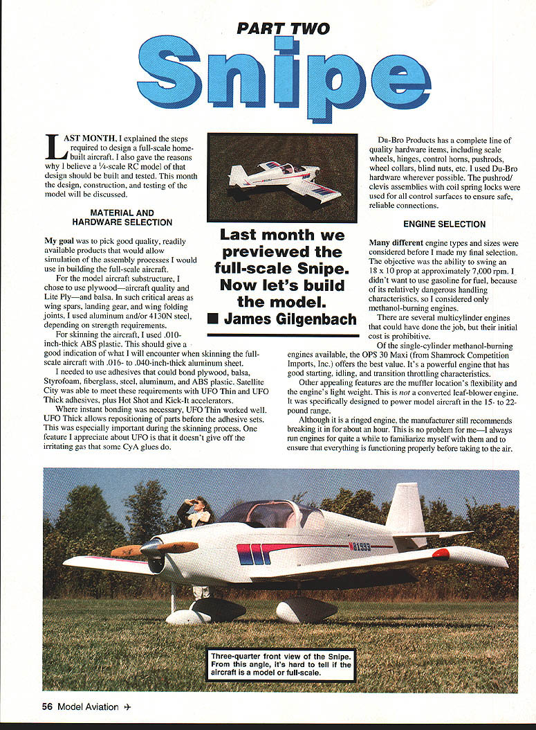
Last month I explained the steps required to design a full-scale homebuilt aircraft and gave the reasons why I believe a 1/4-scale R/C model of that design should be built and tested. This month the design, construction, and testing of the model are discussed.
— James Gilgenbach
MATERIAL AND HARDWARE SELECTION
My goal was to pick good-quality, readily available products that would allow simulation of the assembly processes I would use in building the full-scale aircraft.
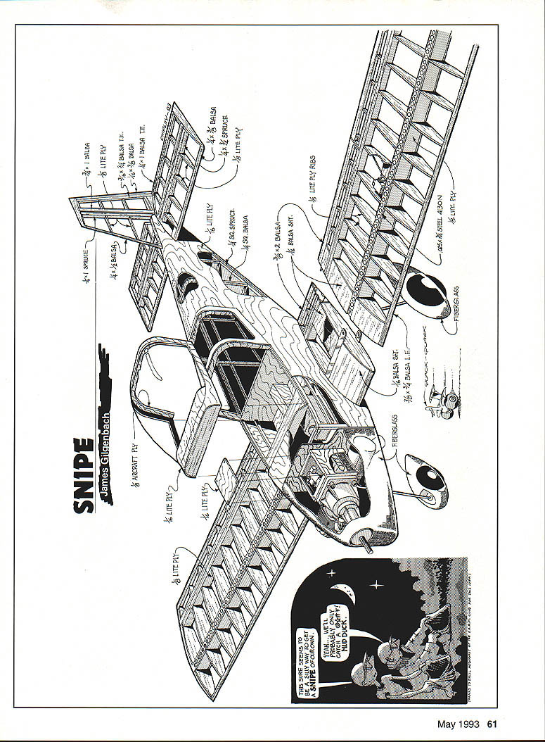
- Substructure materials: aircraft-quality plywood, Lite Ply, and balsa. In critical areas (wing spars, landing gear, wing-folding joints) I used aluminum and 4130 steel depending on strength requirements.
- Skin: 0.010-inch-thick ABS plastic to simulate full-scale skinning with 0.016–0.040-inch aluminum sheet.
- Adhesives: I needed adhesives that bond plywood, balsa, Styrofoam, fiberglass, steel, aluminum, and ABS plastic. I used UFO Thin and UFO Thick, plus Hot Shot and Kick-It accelerators. UFO Thin is good for instant bonding; UFO Thick allows repositioning before the adhesive sets. UFO adhesives do not give off the irritating gas some cyanoacrylate (CA) glues do.
- Hardware: Du-Bro Products provided scale wheels, hinges, control horns, pushrods, wheel collars, blind nuts, etc. I used Du-Bro hardware wherever possible. Pushrod/clevis assemblies with coil-spring locks were used on all control surfaces for secure connections.
ENGINE SELECTION
Objective: swing an 18 x 10 prop at approximately 7,000 rpm without using gasoline. I chose a methanol-burning engine.
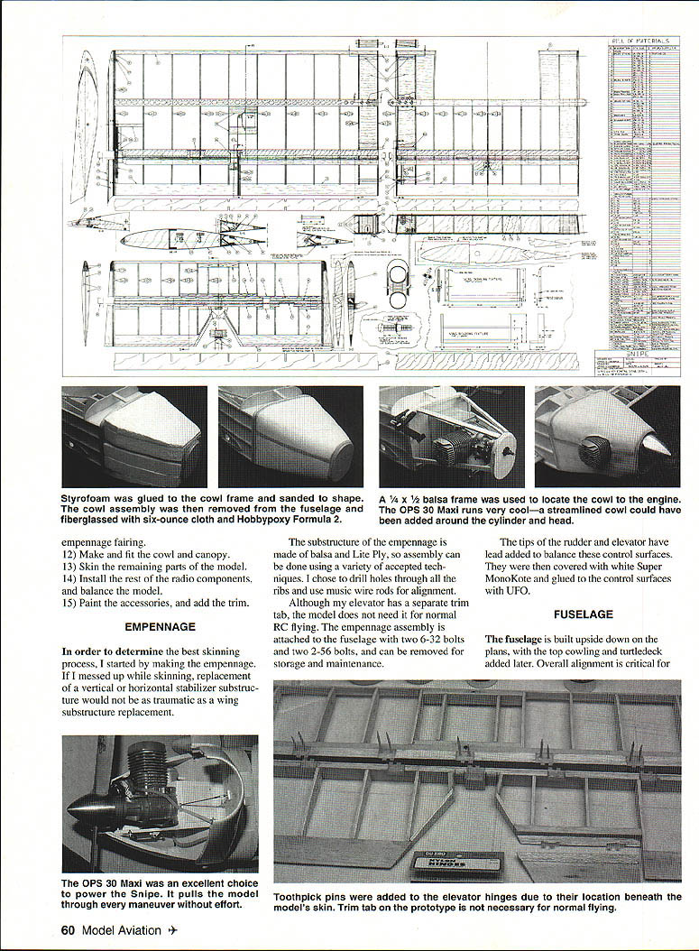
- Selected engine: OPS 30 Maxi (Shamrock Competition Imports). Good value among single-cylinder methanol engines—powerful, light, with good starting, idling, and transition throttling characteristics. Designed for 15–22 lb model aircraft.
- Break-in: Manufacturer recommends about an hour of break-in. I always run engines extensively to familiarize myself with them and ensure proper operation.
- Fuel: Cool Power Tartan/Bully fuel blended for this engine size and type. I had excellent results and noted improved rust/corrosion protection compared to a 5% castor/95% methanol mix.
- Spinner: Lightweight 3-inch aluminum spinner (Tru-Turn TT-300B). I modified a TT-300B by cutting slots to fit an 18 x 10 prop and by drilling/tapping the OPS 30 Maxi prop nut for a 10-32 spinner bolt to lock the prop to the engine in a fashion similar to full-scale practice. Tru-Turn offers a large-scale spinner that may eliminate some of these mods.
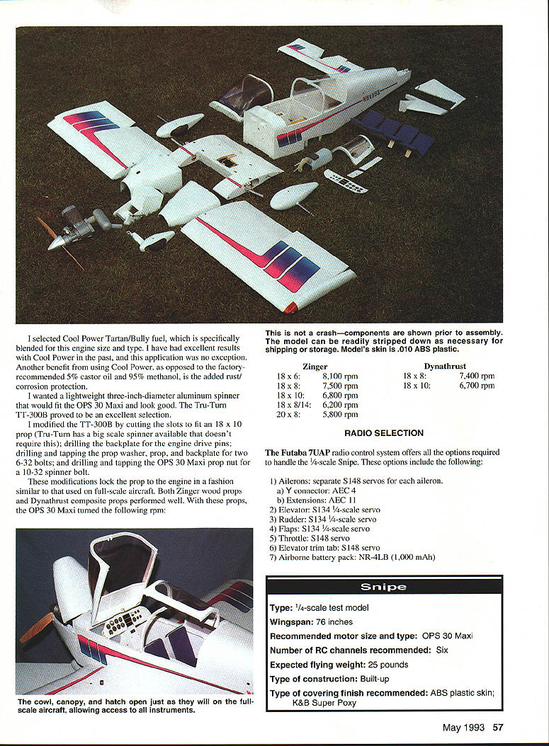
- Props tested: both Zinger (wood) and Dynathrust (composite) performed well. The OPS 30 Maxi turned these rpms:
- Zinger 18 x 6 — 8100 rpm
- Zinger 18 x 8 — 7500 rpm
- Zinger 18 x 10 — 6800 rpm
- Zinger 18 x 8/14 — 6200 rpm
- Zinger 20 x 8 — 5800 rpm
- Dynathrust 18 x 8 — 7400 rpm
- Dynathrust 18 x 10 — 6700 rpm
RADIO SELECTION
I used a Futaba 7UAP radio control system. The programmable transmitter allows fine-tuning of all flight controls without mechanical linkage changes and saved many hours of testing. The built-in timer and tight servos reduce control drift.
Recommended equipment and assignments:
- Ailerons — separate S148 servos; aileron Y connector; AEC-4B extensions; AEC-11
- Elevator — S134 scale servo
- Rudder — S134 scale servo
- Flaps — S134 scale servo
- Throttle — S148 servo
- Elevator trim tab — S148 servo
- Airborne battery pack — NR-4LB 1000 mAh
- Charger — FBC-6B4
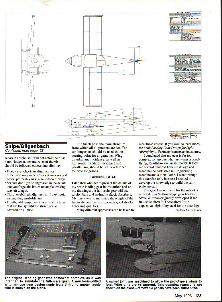
Model specifications:
- Type: 1/4-scale test model
- Wingspan: 76 inches
- Recommended motor: OPS 30 Maxi
- Number RC channels recommended: Six
- Expected flying weight: 25 pounds
- Construction: Built-up
- Covering/finish recommended: ABS plastic skin
- Paint/primer used for miscellaneous parts: K&B primer, then K&B Super Poxy
MODEL CONSTRUCTION SEQUENCE
Basic steps to build the model:
- Build and skin the horizontal and vertical stabilizers, elevator, and rudder.
- Build the fuselage (including the console) without the turtledeck and top. Build the engine/nosewheel mount.
- Make the landing gear parts and the steel spar caps.
- Build the center wing section.
- Build the outer wing sections—leave the top spar cap loose.
- Assemble the wing sections and adjust the dihedral.
- Make and install the flaps and ailerons.
- Fit the wing and the horizontal and vertical stabilizers to the fuselage.
- Install the engine, muffler, and nose gear.
- Install the aileron servos and make the hatches.
- Skin the fuselage interior. Make and install the turtledeck and front fuselage top.
- Make and fit the cowl and canopy.
- Skin the remaining parts of the model.
- Install the rest of the radio components and balance the model.
- Paint accessories and add trim.
EMPENNAGE
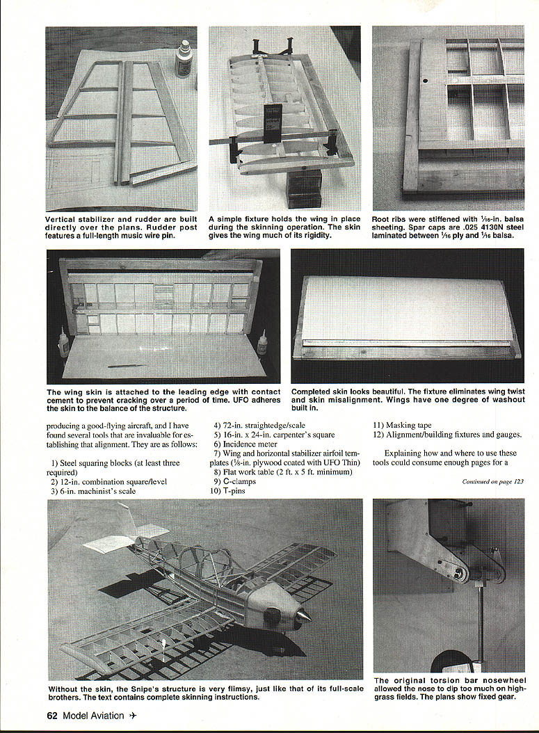
I started with the empennage to determine the best skinning process; mistakes on a stabilizer are less costly than on a wing. The substructure is balsa and Lite Ply and can be assembled with accepted techniques. I drilled holes through all ribs and used music-wire rods for alignment.
- The elevator has a separate trim tab, though the model does not require it for normal RC flying.
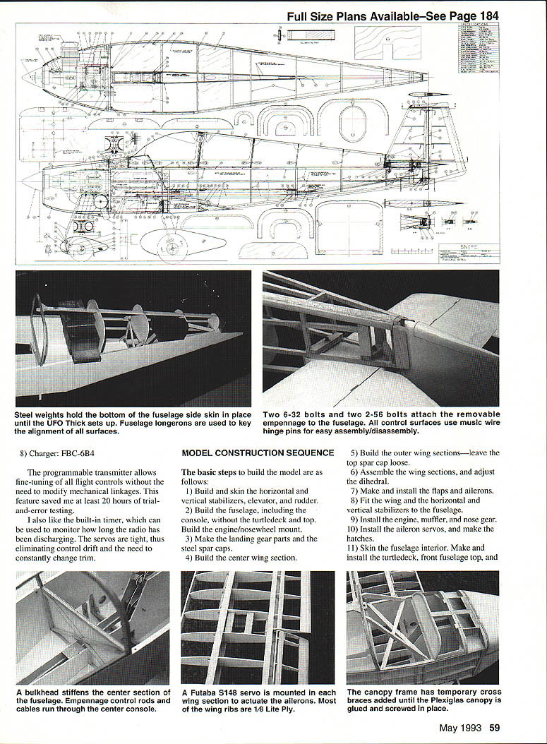
- The empennage attaches to the fuselage with two 6-32 bolts and two 2-56 bolts and can be removed for storage/maintenance.
- Lead was added to the rudder and elevator tips for balance. Surfaces were covered with white Super MonoKote and glued with UFO adhesives.
FUSELAGE
The fuselage is built upside down on the plans; the top cowling and turtledeck are added later. Overall alignment is critical for producing a good-flying aircraft. Useful tools for establishing alignment include:
- Steel squaring blocks (at least three)
- 12-inch combination square/level
- 6-inch machinist's scale
- 72-inch straightedge/scale
- 16 x 24-inch carpenter's square
- Incidence meter
- Wing and horizontal stabilizer airfoil templates (1/8-in. plywood coated with UFO Thin)
- Flat work table (minimum 2 ft x 5 ft)
- C-clamps
- T-pins
- Masking tape
- Alignment/building fixtures and gauges
Rules of thumb for alignment:
- Never check an alignment or dimension only once; check several times and by different methods.
- Don't lose sight of basic assembly (e.g., avoid making two left wings).
- Eyeball alignments—if they look wrong, they probably are.
- Add temporary braces to flimsy structures until they are covered or skinned.
The fuselage is the main reference structure. Use the top longerons as the starting point for alignments. Wing dihedral and incidence, as well as horizontal stabilizer incidence and parallelism, should be set relative to these longerons.
LANDING GEAR
For the full-scale Snipe I planned torsion bars and hydraulic shock absorbers to minimize weight and provide good shock absorption; designing and machining that gear took several hundred hours. For the model, such complexity is unnecessary.
Recommended model gear: Wittman-type gear (music wire). Music wire is strong, less expensive than high-alloy steel, simple, and durable. It is a common, practical choice for models.
If you want to learn more about full-scale gear design, see Landing Gear Design for Light Aircraft by L. Pazmany.
WING
The model wing simulates the folding feature of the full-scale aircraft; the plans show removable wing panels for practical model use.
- Prototype connection: #6 tapered pins were used to hold wing sections together. The plans show a hex-head cap screw with a nylon-insert locknut as an easier alternative.
- Spar caps: unusual feature is .025-in.-thick x 3/4-in.-wide 4130 steel for spar caps.
- Design loads: wing is designed to handle +9.0G and -4.5G ultimate loads. Full-scale normal aerobatic loads are typically within +6.0G and -3.0G. Model flying can produce higher loads—exercise prudence.
Wing building sequence:
- Make a wing fixture from miscellaneous lumber. Make all spars and ribs.
- Cut all 14 steel spar caps (six long, eight short) to length, radius the ends, drill mounting/lightening holes, deburr, and sand.
- Cut 1/8 x 3/4 plywood and 1/16 x 3/4 balsa spar caps and glue them to the steel caps of the outer wing panels only (UFO Thick).
- Cut and notch the plywood spar webs; ensure they fit snugly into the wing fixture.
- Glue the bottom outer front spar caps to the wing webs (UFO Thick).
- Clamp one outer wing panel front spar assembly to the fixture and position the rear spar web with ribs into the fixture.
- Align all ribs and glue them to the spar webs. Note: Do not glue the top front spar cap yet.
- Glue the leading edge to the front of the ribs.
- Glue the rear plywood spar caps to the ribs and rear spar web; remove the assembly from the fixture.
- Screw the bottom outer main spar caps to the wing web block.
- Repeat steps 6–10 on the other outer wing panel.
- Glue 1/16 x 3/4 plywood and balsa spar caps to the center wing steel spar cap.
- Glue the plywood front spar web to the center bottom front spar cap assembly.
- Clamp this assembly to the fixture and position the rear spar web with ribs into the fixture.
- Align the ribs vertically using a square and glue them to the spar webs. Do not glue the top two end ribs yet.
- Glue the top spar cap to the ribs and spar web.
- Glue the leading edge and the two rear plywood spar caps to the ribs and rear spar web; remove the assembly from the fixture.
- Screw the spar caps to the wing web block.
- Glue the four wing-locating dowels in place on the outer wing panels.
- Assemble the outer wing panels to the center wing panel and adjust dihedral angles by sliding the top wing spar caps on the outer panels.
- Clamp the two end ribs of the center wing section to the two end ribs of the outer wing sections with 0.020-in.-thick shims between the ribs. The shims equal the thickness of two pieces of 0.010-in. ABS plastic.
- Glue the top outer wing spar caps and center section outer ribs in place.
- Screw the top outer wing spar caps to the wing web block.
- Shape and sand the leading edges of the three wing panels to match.
- Ailerons and flaps: build over the plans on a flat surface. Align and glue interconnecting flap linkages with the swivel joint installed while the flap sections are aligned on the wing in the retracted position.
- Hinges: all control surfaces use music wire through the hinges for easy assembly/disassembly.
- Wing tips: balsa and plywood tips bolted to the outer wing rib with two 6-32 socket-head cap screws. They could be glued, but I bolted them to try different tip types for best stall characteristics.
CANOPY
Canopy forming procedure (0.040-in. Plexiglas):
- Make the plug from wood and coat it with epoxy.
- Sand the epoxy smooth—the inside texture transfers to the formed canopy.
- Attach handles to two sides of the Plexiglas sheet.
- Heat the sheet and plug in an oven until the Plexiglas starts to sag.
- Remove both from the oven and stretch the Plexiglas over the plug. Repeat as needed to refine shape.
- Make the canopy frame.
- Trim and attach the canopy to the frame using UFO adhesives and #1 flat-head wood screws.
COWL AND WHEEL PANTS
Cowl construction sequence:
- Cut out the plywood cowl framework.
- Glue the framework to several Styrofoam blocks.
- Cut and sand the Styrofoam to shape.
- Cover the assembly with a layer of 6-oz. fiberglass cloth. I used Hobbycoy Formula 2 to bond and fill the cloth.
- After the epoxy hardens (wait at least a day), trim excess fiberglass, sand rough edges and high points, and apply a heavy coat of Hobbypoxy mixed 50/50 with microballoons.
- Wait at least a day, then rough-sand the outer surface to shape.
- Split the cowl and hollow out the Styrofoam, leaving a 3/8-in.-thick Styrofoam wall inside each half.
- Sand the Styrofoam wall smooth and apply one layer of 6-oz. fiberglass inside each half.
- Wait another day, then trim and sand excess fiberglass. Add hinges and hold-down latches (hinges with 1/2-in. pins).
- Reassemble the halves and finish sand. To assure a good fit, attach the cowl to the fuselage and match-sand. Compensate for the 0.010-in. ABS fuselage skin.
Wheel pants:
- Form a Styrofoam plug, cover with two layers of 6-oz. fiberglass, coat with the 50/50 epoxy/microballoon mix, sand to shape, and hollow out the Styrofoam.
SKINNING, PAINT, AND TRIM
General skinning procedure for 0.010-in. ABS plastic:
- Sand the stabilizer contour smooth and remove dust.
- Cut the ABS skin slightly larger than the area to be covered; cut to wrap around the leading edge and allow overlap at the trailing edge.
- Place the skin on a hot (≈100°F), flat surface and tape down one end (I used a glass-topped dining table with a space heater underneath).
- Run a bead of UFO Thick on the trailing edge and all ribs up to the leading edge on the top side of the horizontal stabilizer. Start with the top skin so the best part of the job is visible.
- Press the trailing edge onto the skin, leaving a 1/4-inch overhang. Hold pressure for about one minute as the UFO sets.
- Remove the assembly, apply UFO Thick to the leading-edge top, front, and bottom.
- Tape the skin edge to the table and roll the stabilizer onto the skin. Hold pressure for about one minute.
- Remove and trim edges with a sharp knife and sanding block. When cooled, the skin should be tight and stiff.
- Exposed rib sides can be covered with ABS and paint or a heat-shrinkable covering.
Folding ABS at control-surface trailing edges (technique):
- Build and sand the control surface; remove loose particles.
- Cut the ABS skin slightly larger than required.
- Lay a thin (0.025-in.) steel straightedge on the skin at the fold line and weight/clamp the ends.
- Score the fold line with a hard pencil—press hard so the plastic is scored but not deeply scratched.
- Fold the skin over the straightedge to create a 180° bend.
- Remove the straightedge and fold the skin flat; the fold line should be straight.
- Tape the top side of the skin to the heated glass table.
- Apply UFO Thick to the top side of the control-surface substructure.
- Position the substructure onto the skin; press and roll it to attach. Hold pressure for about one minute.
- Remove the assembly and apply UFO Thick to the opposite side of the substructure.
- Repeat step 9 on the opposite side.
- Trim off excess skin.
Notes and tips working with ABS:
- If epoxy is spilled on the plastic, denatured alcohol removes the epoxy before it sets. Once set, epoxy is difficult to remove and may require sanding.
- Removing UFO from ABS: use a small amount of Zap Z-7 Debonder on a rag and lightly wipe. Don’t rub too hard—Z-7 can dull or cut the plastic.
- If the surface dulls, restore shine with Turtle Wax white automotive polishing compound.
- Scratches can be removed by sanding with 1200-grit wet-or-dry sandpaper, then polishing. Don’t push too hard or the skin may crack at attachment points.
- The plastic can be shrunk with a heat gun but is easy to melt and may warp the substructure—heat-shrinking is not recommended.
- To minimize wrinkling in sunlight, preheat the plastic before installation.
- K&B thinner cuts into ABS; K&B epoxy bonds well when thinned with K&B thinner. For cleanup, use denatured alcohol, not K&B thinner.
- Miscellaneous parts (plywood, balsa, spruce, steel, aluminum, brass, epoxy, fiberglass, ABS) were primed with K&B primer and finished with K&B Super Poxy—this paint sands and holds up well.
Trim:
- I used the Jumbo Stripe Kit from Eagle Products for stripes and decals. They are easy to install, durable, and come in several color schemes. I preferred a fluorescent pink/blue/purple combination.
TESTING — AT HOME
Before going to the flying field:
- Check center of gravity (CG): should be between 23% and 27% of wing chord. I flew initial flights at 28% but recommend adding nose weight if necessary to get CG to 25%.
- Test-run the engine in the aircraft at the field to check cooling, fuel flow, and starting from hand.
- Check exhaust for leaks at the muffler and joints; correct any fuel or oil leaks before flying.
- Do radio range checks per the manufacturer's recommendations: bench check, then in the airplane on the ground, then with the engine running and radio at full power and distance. Tie down the plane during these tests.
- Taxi the aircraft to familiarize yourself with ground-handling characteristics.
- After running and taxiing, inspect all linkages, nuts, and bolts. If components are loose, find the cause—glue or Loctite as needed.
PREFLIGHT
When ready to fly:
- Avoid crowded flying fields for a first flight.
- Limit helpers to two: an experienced model builder/pilot and a camcorder operator. Videotape the entire session, including preflight.
- If weather is adverse, reschedule.
- Conduct a preflight inspection: check linkages/connectors, control-surface directions and throws, run the engine at different attitudes, and range-check the radio.
FLIGHT PLAN
Planned sequence for initial flights:
- Take off into the wind (northwest at my field). If the engine dies on takeoff, land straight ahead into the wind.
- At ~200 ft altitude and ~200 yards distance, perform a 180° right turn.
- Climb to 300 ft and fly 400 yards to the southeast.
- Perform a left-hand procedure turn.
- Fly 400 yards to the northwest, trim controls, and perform a right-hand procedure turn.
- Fly 400 yards to the southeast.
- Repeat steps 4–6 several times, trying both high and low elevator/aileron rates and verbally noting control responses to the helper and video camera.
- Test flight characteristics with flaps down.
- Enter a right-hand landing pattern and land with flaps down if possible.
Flight observations:
- After the first flight, inspections revealed nothing loose.
- Prototype was stable but too responsive even on low rates. Activating flaps produced no pitching tendency. With 25° flaps and engine at idle, landing was relatively slow for a 25-lb aircraft.
- On the second flight, aerobatic characteristics resembled a pattern ship. A landing without flaps was disastrous—caught a wingtip and damaged the left wing and nose gear.
- Video analysis showed I flared too soon and too much on the second landing, then overcorrected; causes included too much elevator and aileron throw with the CG at 28% and rusty flying skills.
- Subsequent flights checked stall and spin characteristics at different weights and CG locations.
TEST RESULTS
- The model flies well with the CG at 25%.
- With drooped wing tips, the stall is straight with no tendency to snap roll or drop a wing tip.
- At slow ground speeds, it is difficult to turn the model without a steerable nose wheel or individual main-gear brakes.
- The ABS skin does not vibrate excessively regardless of engine rpm.
- Theoretically, the model should fly well at 34 pounds, but I have not tested this yet.
- Elevator trim changes are not required when the flaps are activated.
- Landings were docile with 20°–40° of flaps. Forty degrees slows the plane quickly and increases rate of descent.
- No control flutter was encountered.
- The aircraft will not spin with the CG less than 20%, even with full control travel.
CONCLUSIONS
This project benefited from the help and encouragement of many individuals and organizations. I strongly recommend modelers patronize the manufacturers and distributors mentioned in this article. Special thanks to my flight assistants: Gus Rebensburg, Jerry Reichow, and Duncan Stewart.
Based on these tests, I am convinced it is feasible to develop a full-scale Snipe. I will continue to use the 1/4-scale model to test different features and building techniques as I detail-design the full-scale aircraft.
Additional notes:
- Balancing: I sometimes do a quick manual balance on my fingers, but for accuracy I use a simple balance stand—1/4-inch plywood or balsa cradle with supporting fillets and a rounded top edge. The stand allows precise balance-point measurement and easy weight adjustments.
- Retractable gear: For meticulous scale builders, commercial retract systems such as Cope Retracts are worth considering. Cope offers multiple sizes (including a 1/4-scale unit). Contact: Cope Retracts, 3203 Main St., Union Gap, WA 98903; (509) 457-9017.
By the summer of 1998 I will report on how the full-scale aircraft flies. Meanwhile, I will keep testing with the 1/4-scale model and experiment with building techniques. I can't wait to get started bending tin!
Transcribed from original scans by AI. Minor OCR errors may remain.

