

PAT-1 Peanut
Robert Womack
The PAT-1 is the prototype for an all-composite (plastic) canard lightplane designed from the start to be commercially produced. I'm not sure whether it is the first lightplane so designed, but I understand it is the first canard lightplane designed for commercial production. Aircraft manufacturers on both sides of the Atlantic have been trying since the mid-1950s to produce a powered composite aircraft commercially. (See Peter Garrison's article in the April 1982 issue of Flying magazine regarding techniques and earlier attempts.)
Although a canard, the PAT-1 looks much the same as any other four-place, low-wing, single-engine, fixed-gear plane. The wing is just aft of where it usually is, the fuselage is about the same size, and so is the vertical fin/rudder. What sets it apart is moving the stabilizing surface from the tail to the front (that's what makes it a canard) and attaching the main landing gear to the fuselage like a Cessna. Peter Lert, test pilot on the development project, has a pilot report in the November 1981 Air Progress magazine accompanied by several outstanding photographs by Budd Davisson.
So the PAT-1 held promise as an easy-handling plane capable of carrying a large payload (1,000 lbs.). The future is now in doubt because of the death of the company's president, Howard Piper, shortly before the maiden flight in June 1981 — and the deaths of the plane's designer, George Meade, and two NASA engineers in the crash of the only prototype while on a demonstration flight in November 1981.
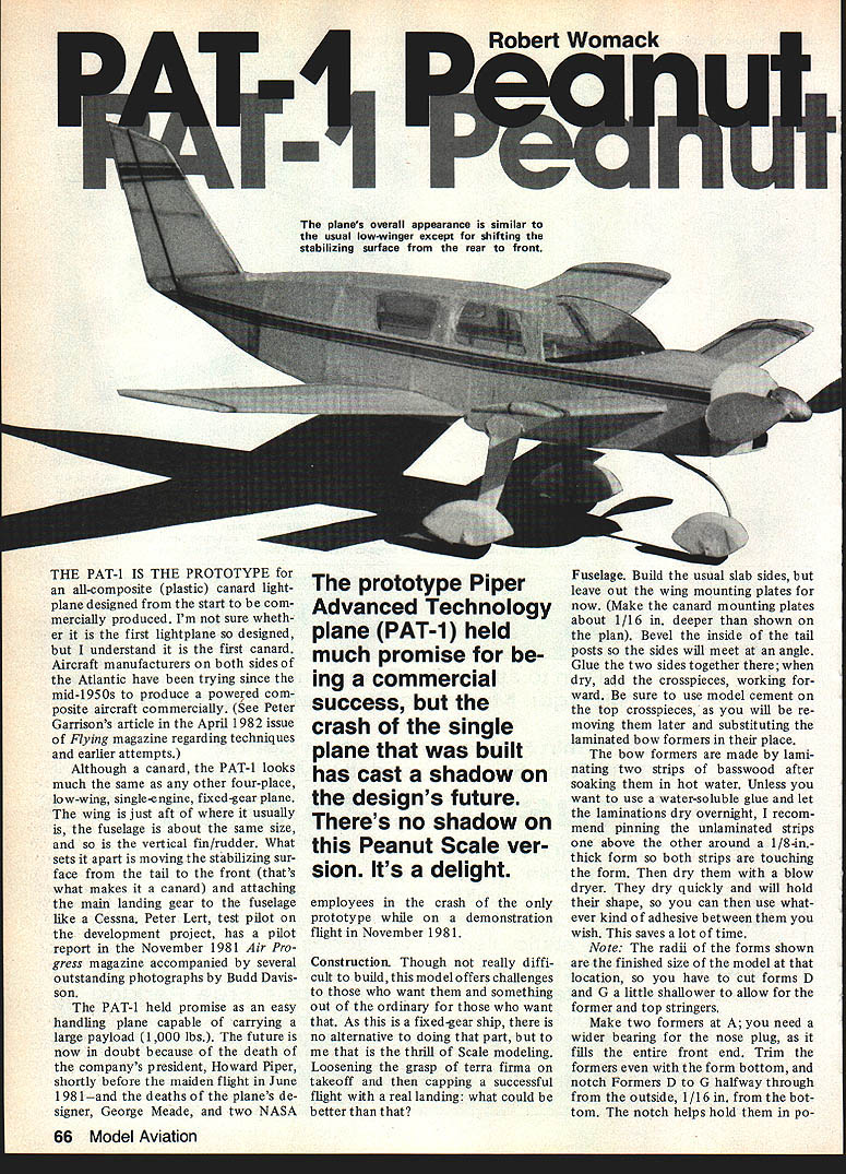
The prototype Piper Advanced Technology plane (PAT-1) held much promise for being a commercial success, but the crash of the single plane that was built has cast a shadow on the design's future. There's no shadow on this Peanut Scale version. It's a delight.
Fuselage
Build the usual slab sides, but leave out the wing mounting plates for now. (Make the canard mounting plates about 1/16 in. deeper than shown on the plan.) Bevel the inside of the tail posts so the sides will meet at an angle. Glue the two sides together there; when dry, add the crosspieces, working forward.
Be sure to use model cement on the top crosspieces, as you will be removing them later and substituting the laminated bow formers in their place. The bow formers are made by laminating two strips of basswood after soaking in hot water. Unless you want to use a water-soluble glue, let the laminations dry overnight. I recommend pinning the unlaminated strips one above the other around a 1/8-in.-thick form, both strips touching the form. Dry with a blow dryer and they'll hold shape. You can use whatever kind of adhesive between them you wish. This saves a lot of time.
Note: The radii of the forms shown are the finished size of the model at that location, so you have to cut forms D and G a little shallower to allow for the former and top stringers.
Make two formers at A; you need a wider bearing for the nose plug, as it fills the entire front end. Trim the formers even with the form bottom, and notch formers D to G halfway through from the outside, 1/16 in. from the bottom. The notch helps hold them in position. Use Scotch tape to hold the formers until the adhesive dries.
The area ahead of the windshield is covered with 1/64 in. sheet; approximately 1/32 in. sheet is used, sanded, for compound-curve areas. Scotch tape will be required to hold the covering while the glue dries. Two fillets C give the curve to the front cabin. Add wing mounting plates, cabin stringers, and the brace between the wing mounting plates. Also add a pair of 1/16 x 1/8 in. braces between the top and bottom crosspieces at the leading and trailing edges for canard support and the front landing gear mount — two braces are clearly indicated on the plan.
Nose block
Cut pieces from 1/8 in. sheet balsa so they may be glued cross-grain. Cut the rearmost piece first; make each succeeding piece a little smaller for easier shaping. Glue and round the spinner base. Trim to rough shape; cut away the lower half to the depth of the air scoop box and save the removed pieces.
Build the air scoop box from 1/16 in. scrap, using the saved end pieces glued onto the ends of the air scoop box. Fill between the spinner base and the air scoop box with scrap, shape and smooth, and fillet. Angle the front nose block per the side view. Sand to final shape and hollow out the nose block; add a 1/16 in. back plate.
Finish
Give two coats of Aerogloss sanding sealer and two coats of Aerogloss Swift white enamel. I used a small Peck-Polymers nylon thrust bearing, drilled with a 1/8 in. hole, starting with a small drill bit and gradually working larger to accommodate the spinner-turned pin.
The spinner is turned from a piece of hard 1/2 x 1/2 x 5/8 in. balsa, shaping it with an emery board and then fine sandpaper. Hollow it out, and then fit it to a 4-in. Kaysun plastic prop. If the cuts do not come out right the first time, fill them with soft balsa and recut. Assemble the parts on the 1/32 in. prop hook, and bend over only a very short section on the end; remember, it has to fit inside the spinner. Glue on the spinner, then paint it and the prop silver.
Wing and canard
Sand the trailing edge stock to a triangle shape for both the wing and canard. The wing uses split-rib construction, except for a solid root rib. Pin down the leading and trailing edges, and glue in the rib bottoms (1/32 in. sheet), tip block, and main spar. Cut the rib tops long to allow for the airfoil curve. Put the curve in with your fingers back past the main spar to prevent it from cracking and to give a smooth airfoil. Trim the ribs to length, and glue in place. Slide in the secondary spar to where it touches the tip block and all the rib tops, and then glue it.
Conform the root rib to the mounting plates in the fuselage, then raise the wing tip 3/4 in., and glue in the root rib vertical to the building board. This builds in the dihedral, more or less. Now make the stick gussets, and glue them in the corners of the wing. Sand the tip block to shape, and round the leading edge.
The canard uses standard construction, except for the laminated leading edge. The tip is elevated 3/8 in. to install the root rib. Sand the tip block to shape, and round the leading edge.
Fin and rudder
Initially, I used 1/16 sq. balsa, but later built another one using 1/20 sq. I also left out the diagonal crosspieces on the later version. Both changes were for weight reasons. Sanding a little on two adjacent sides of the 1/16 in. balsa brings its profile close to 1/20.
Note: The balsa stick forming the base of the fin should continue on through to the rudder. This piece does not show on the plan because of the jumble of lines that would have resulted, so you have to remember to add that piece. Before covering, round all outside edges, except where the fuselage is contacted.
Landing gear
See the plan of the wheel fairings (pants). The parts with the cutouts are made from 1/8 in. sheet on the main gear and 1/16 in. sheet on the front gear; all fairings have 1/32 in. outside covers. Do not round the bottom edges of the fairings. Bend the front gear wire to conform to the inside of the front fairing.
Make a 1/16 in. hole in the top of the fairing; insert the wire from the bottom and out the hole, then slide the 1/16 in. aluminum tube sleeve down over the wire and into the hole. Epoxy the wire inside the fairing, and also put epoxy around the hole on the outside. Put aside to dry.
Bend the main gear wire per the front view of the plan; also, cut and bend the short spur. Attach the spur to the rear of the main wire with fine wire, and lightly solder. (The field coil of an electric clock will yield a lifetime supply of fine copper wire — better get a discarded clock, though.) Make the gear mount from 1/16 in. scrap, and attach it to the gear wire with white thread.
The main wheels are hollow 1/8 in. "doughnuts" covered with 1/32 in. sheet "rounds" glued cross-grain. The front wheel has two "rounds" of 1/16 in. sheet glued cross-grain. Sand the sides of the front wheel slightly so it will turn inside the fairing. Install 1/16 in. aluminum tube bushings in all wheels, then round the edges and color with a black felt-tip pen.
Going back to the front gear, bend the sleeve and wire inside it around a cylindrical object held in a vise. (It takes a lot of pressure to make the bend, so use a vise to hold it for safety's sake.) Carefully cut away the excess sleeve material, being careful not to score the wire inside it. Bend the exposed wire to shape, and cut off the excess.
Assemble the front wheel in its fairing, and secure the axle with tiny retainers of clear acetate. Make the front gear mount (two pieces of 1/16 in. sheet scrap) and sandwich the front gear in position between the two pieces with epoxy. Wrap the mount with white thread, and put epoxy on the thread wraps — also on the ends of the axle. Assemble the main wheels in their fairings on the main gear wire, and secure with acetate retainers on the outside. Epoxy the fairings to the struts; put epoxy on the thread wraps and a drop on the end of each axle.
Windshield
This is molded over a form shaped from a block of hardwood (or balsa) 2 x 1-7/8 x 1 in. with a dowel glued in the bottom for a push stick. Use thin wood strips to secure a piece of clear acetate to a 6-in. square piece of fiberboard or plywood in which a cutout 1/8 in. larger than the bottom of the form has been made.
Heat the acetate with an electric source (stove or heater — never over an open flame) until it is "floppy." Test with the eraser end of a pencil; when heated sufficiently, shove the form up from the bottom and through the hole far enough for the acetate to cover the sides of the form. After cooling, remove the acetate from the fiberboard, and trim it to fit.
Covering
First, remove any excess glue blobs with a modeling knife or razor blade, and sand all of the parts. Next, locate the wing and canard incidence lines on each side. The wing is set at +2 degrees. Using a millimeter (mm) ruler, measure from the top of the top longeron to the center of the bottom longeron at F. Now, measure down an additional 2 mm at the leading edge of the wing, and connect the two points with a pencil line.
The canard has +2 degrees incidence. Measure down 10 mm from where the top covering meets the side at the trailing edge of the canard and 8 mm at the leading edge. Again, draw the pencil line on each side. Give the framework (where the tissue will be attached) two coats of full-strength clear dope.
All flying surfaces (wing, canard, fin, and rudder) are covered in the usual fashion; the tissue is then dampened with water and alcohol (50/50) to shrink it and pinned down to a flat surface while drying. The contrasting color stripes, dope, and control surface outlines are cut from dark blue and black tissue, respectively, using a metal straightedge and a new razor blade. Brush on a line of clear dope where the trim is to go. When dry, position the strips and brush on thinner to secure them. After all stripes, etc., have been applied to the flying surfaces, brush (or spray) on one coat of clear thinned dope (50/50) over all of the surfaces.
The fuselage is covered in several sections. The cabin is divided into left and right halves, and each half into four sections. Do the window sections completely before proceeding to the rest of the cabin. First, make band-paper templates of the window sections on one side (just reverse them for the other side), complete with window outlines. Cut out the tissue for these sections, draw on the window outlines in pencil, and apply the tissue. After it is firmly attached, shrink the tissue; when dry, apply two coats of clear thinned dope, allowing drying time between coats.
While this is going on, cut out the clear acetate windows as per the templates; make the windows about 1/16 in. larger so you will have a gluing area. Cut out the window holes, and apply a bead of model cement to the inside of each hole. Position one window inside the cabin, and attach it using thinner. Hold in position until the softened cement begins to set. Attach the other three windows in like manner.
The rear portion of the cabin is closed with four pieces of tissue, then the sides are covered with one piece for each side. Finally, cover the area ahead of the windshield. This last section should be done wet (lay the tissue in position, dampen with water, and smooth out any wrinkles; apply thinner to stick it down).
The black glare shield beneath the windshield is done by taping the windshield in position at the rear, sliding a piece of black tissue under it, and marking the outline of the windshield. Cut out the outline, remove the windshield, and apply the tissue. When dry, cut out the curved front of the cabin.
The fuselage bottom is not covered until all of the parts (except the landing gear fairings) have been assembled. Don't forget the color strips on the fuselage sides — and the windshield.
Assembly
Remove the tissue from the wing and canard attachment areas using thinner to loosen it. Attach the wing and canard panels one at a time; use model cement so the panels can be easily repositioned if necessary. Hold at the approximate dihedral angle until the cement starts to set, then put the assembly on the building board with the appropriate fuselage section flat on the board, and block up the wing and canard to the proper dihedral angles. (It is advisable to weight the fuselage from the inside — or use some other method to hold it down on the board in the proper position.) When the attachments are thoroughly dry, glue on the fin/rudder and landing gear assemblies.
The fuselage bottom is then covered in sections, the tissue shrunk and doped. Make the landing gear fairings from bond paper and install, gluing only to the inside seam and at the bottom. Leave the top free so the gear can flex without tearing the covering.
Flying
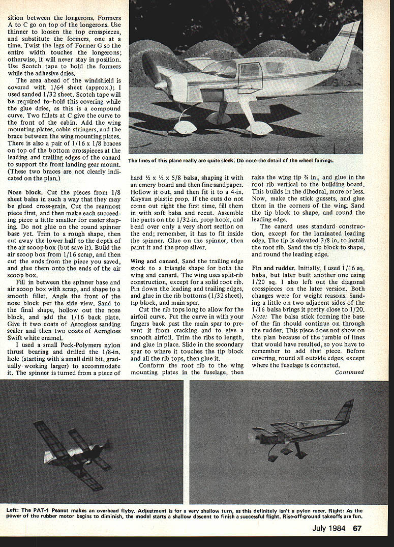
For power, I use an 11-in. loop of 1/8 in. rubber. Install a lubed motor, and balance the model at the point shown. My model required no additional weight. Test gliding will show whether the wing and canard have the proper angles of incidence. Use more negative incidence in the wing to correct a dive, and less positive incidence in the canard to correct an up-swoop.
Put in about 500 turns on the motor, and let the model rise off ground from its wheels. It should take off, make a few circles to the left, and come in for a landing. If your model refuses to take off, reduce the amount of downthrust. If all is okay, add more winds. You will probably need about 3/32 in. wash-in on the left wing tip; this isn't a pylon racer, so you want the turns to be fairly flat.
I get flights of about 23 seconds outdoors with a hand launch — without thermal assistance. My model weighs 15 grams without the motor. If you can build lighter, you should do much better.
I hope you enjoy building this model, and I know you will enjoy the sight of this unique design in flight — as well as those takeoffs and landings. Happy flying.
Acknowledgement: Thanks to my brother, Elmer Womack, for inking my drawing.
Transcribed from original scans by AI. Minor OCR errors may remain.

