

Paygo
James M. Mills
Overview
Especially attractive to junior and senior class modelers with a minimum of building time, Paygo is a simple model designed to compete in both Payload and Cargo events. It has placed first in both events at the Nationals.
At the 1974 Lake Charles Nationals, Paygo placed first in Junior Payload and first in Junior Cargo. At the 1976 Dayton Nationals it placed first in Junior/Senior Cargo and second in Junior Payload.
Alignment can be checked by placing the partially assembled fuselage over the top view. A chief cause of trouble is failure to get the rudder post exactly on the center line and at right angles to the board. Cabin assembly is easy if parts are installed in the order described below. Many of the fine points are similar to simple RC jobs. Keep the structure square and free of warps during construction for a fine contest plane.
Fuselage
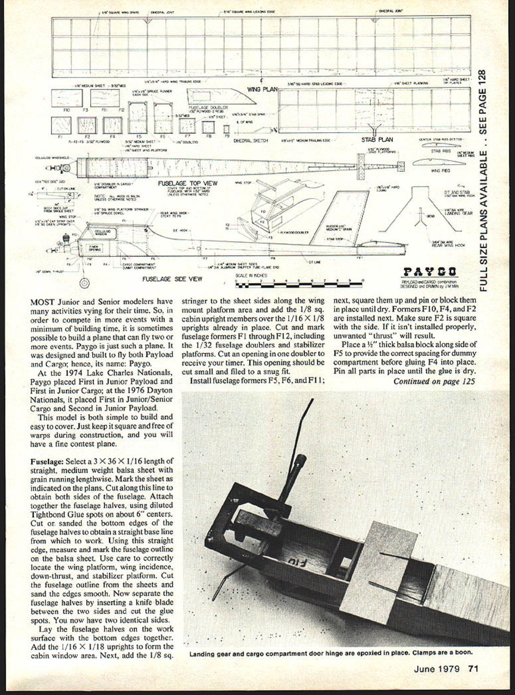
Select a 3" x 36" x 1/16" length of straight, medium-weight balsa sheet with the grain running lengthwise. Mark the sheet as indicated on the plans and cut along this line to obtain both sides of the fuselage. Attach the fuselage halves using diluted Titebond glue spots on about 6" centers. Cut or sand the bottom edges of the fuselage halves to obtain a straight baseline from which to work. Using this straight edge, measure and mark the fuselage outline on the balsa sheet. Use care to correctly locate the wing platform, wing incidence, down-thrust, and stabilizer platform. Cut the fuselage outline from the sheets and sand the edges smooth. Now separate the fuselage halves by inserting a knife blade between the two sides and cut the glue spots. You now have two identical sides.
Lay the fuselage halves on the work surface with the bottom edges together. Add the 1/16" x 1/8" uprights to form the cabin window area. Next, add the 1/8" square stringer to the sheet sides along the wing mount platform area and add the 1/8" square cabin upright members over the 1/16" x 1/8" uprights already in place. Cut and mark fuselage formers F1 through F12, including the 1/32" fuselage doublers and stabilizer platforms. Cut an opening in one doubler to receive your timer; make this opening small and file to a snug fit.
Install fuselage formers F5, F6, and F11; square them and pin or block them in place until dry. Next install formers F10, F4, and F2. Make sure F2 is square with the side; if it isn't installed properly, unwanted thrust will result. Place a 1/2" thick balsa block alongside F5 to provide the correct spacing for the dummy compartment before gluing F4 into place. Pin all parts until the glue is dry.
Glue the other fuselage side in place. Glue and pin the body halves together at the rear to assure proper alignment. When dry, check alignment and glue formers F7, F8, and F9 into place.
Form the wire rear wing hook and epoxy it in place on former F6 as shown on the plans.
Install 1/16" balsa scrap doublers at the DT snuffer tube location. Cut a snuffer tube from 1/4" diameter aluminum tubing and flare one end to allow easy installation in the fuselage. Drill or file holes where indicated in the fuselage and install the DT tubing with the flared end located on the left side.
Plank the top and bottom of the fuselage using 1/32" hard balsa sheet with the grain running across the width as indicated on the plan. When the glue is dry, cut the planking flush with the sides and sand smooth. Plank the wing platform with 1/16" sheet and add 1/16" x 1/8" runners. Install the motor mount former F1 and add 1/32" plywood doublers on each side of the fuselage.
Locate a Cox .020 tank-mounted motor on the firewall. Mark the mounting bolt locations and drill out to receive the engine mounting bolts and blind nuts. Bolt the engine in place and install former F3 and the landing gear. Notch former F3 to allow room for the mounting bolts and epoxy in place.
Install the wing and tail surfaces on the fuselage. When the plane is covered and finished, add the cargo door and gear door to the bottom of the fuselage.
Install former F12 and 1/32" plywood bottom planking from motor mount former F1 back to the dummy compartment. The dummy and cargo compartment door is made of 1/32" plywood with a 1/16" doubler at the cargo compartment. The compartment door is hinged at the rear and held closed at the front with two small screws—or with two hooks and a rubber band, if you prefer.
Construct the rudder from medium-weight C-grain balsa with grain as shown on the plans. Glue the stabilizer stop to the stabilizer platform and install the platforms on the fuselage.
Apply one coat of sanding sealer to the fuselage. When the sealer is dry, sand smooth with #400 sandpaper. Add three coats of clear dope to the area where the windshield is to be attached. Cut the windshield celluloid to shape and, while holding it in place, apply dope thinner to the edges of the celluloid with a brush; the thinner will soften the dope and seal the windshield in place.
Remove the motor and paint the body with three coats of fuel-proof colored dope. The original model was painted yellow to make it easier to spot in grass and trees.
Wing and Stabilizer
Start by making a set of master ribs for both the wing and the stabilizer by spot-gluing two pieces of 1/16" plywood together. Cut the wing and stabilizer rib patterns from the plan and glue them to the plywood. When the glue is dry, cut out the rib outlines and sand them smooth. Carefully separate the 1/16" plywood and you have a set of master ribs. Count the ribs required of each type and cut that number of 1/16" medium balsa strips slightly larger than the master ribs. Stack the balsa strips between the plywood ribs and drive two straight pins through the master rib into the balsa stack from both sides to hold the assembly together. Sand the edges of the balsa stack so it will fit flush with the plywood master ribs, then file notches for the spars. Remove the pins and you have a set of identical ribs.
The wing trailing edge is cut from a sheet of 3/8" hard, straight-grain balsa, tapered with a razor plane or by sanding to shape. Mark the rib locations and file or cut 1/16" notches to the depth indicated on the plan.
Place waxed paper over the plan and pin the leading edge, bottom spar, and trailing edge in the locations shown. Glue all ribs in place and install the top spar on the flat center section between dihedral joints. While the wing center section is pinned down to the work table, cut notches in the leading and trailing edges. After cutting these notches, raise the wing tips to the proper dihedral height, then block and glue in place. Now glue in the top spar and wing rib gussets at the leading edge.
Construction of the stabilizer is similar to that of the wing except the center three ribs are cut out to receive the 1/16" sheet planking as shown. Next form the stabilizer wire hooks and glue them in place.
Cover the wing, rudder, and stabilizer with transparent MonoKote and shrink tight. When tightening the covering on the wing tips, block the trailing edge up 1/8" at the tip to provide the washout required. With washout (trailing edge up) the wing center section will stall before the tips, giving a more stable flight.
A dark covering for the wing, such as red, stands out well against the blue sky and white clouds, making it easier for a timer to keep track of the plane.
Epoxy the rudder in place, making certain it is absolutely straight with the center line of the fuselage.
Mount the wing on the wing platform and square it to the body. Mark the location of the fuselage on the bottom of the wing and cut away a little covering. Epoxy some wing keys in place to maintain the correct alignment each time the wing is fastened.
Mount the motor, timer, wheels, and DT cord. Rig the DT cord to allow the rear of the stabilizer to rise to a 45°–50° angle when the fuse burns through the DT rubber band. Assemble wing and tail on the fuselage and put the dummy in place. Balance the plane at the point indicated on the drawing.
Flying
Hand-glide the model over a grassy area. Run with the plane until you feel a little lift, then gently push forward so as not to cause a stall. Do not attempt to fly the model if it is tail heavy; add weight to the nose if necessary.
First flight recommendations:
- Make the first flight with about 3/4 power.
- Use a five-second engine run if hand-launched, or an eight-second engine run for a takeoff.
- Observe the flight pattern and make necessary adjustments before attempting a full-power flight.
The original model flew to the right under power and had a left-turning glide, which was controlled by raising the left stabilizer tip 1/8" high. The right wing had a 1/4" x 1" tab turned down 3/32" to help hold the right wing up while under power. Use a small rudder tab to control the climb pattern if necessary.
When flying Paygo in Cargo events, load the compartment without attempting to maintain the balance point. All cargo weight is in front of the balance point and the model flies almost as well fully loaded as it does without cargo.
Properly constructed and trimmed, Paygo is fun to fly and should add trophies to your collection.
Transcribed from original scans by AI. Minor OCR errors may remain.

