
PBA Special
Frank Scott
THE IDEAL control-line trainer has long been an elusive sort of bird, and curiously enough, the more successful a trainer is, the less often it will be flown! Our reasoning is this: the really well-conceived trainer will quickly prepare the fledgling for more exciting craft, and having thus mastered the lowly seeming, yet most important trainer, the flier will abandon it for airplanes better suited for more advanced flying.
Our PBA Special then, is a design intended to grow with the flier's capabilities. Starting as a sturdy, steady Primary trainer, then with a new wing becoming a Basic stunt trainer, and then, with the addition of wing flaps, the metamorphosis is completed as the Advanced stunt trainer.
The PBA Special is thus much like the Army Air Corps training program of World War II, in which the Cadet started off in Primary trainers with which he learned to get up and back down without breaking anything expensive, then graduated to the more spritely Basic trainers, in which he really learned to fly, and finally, training was completed in Advanced trainers which taught him how to use the airplane.
So much for the philosophy; let's get on with building this unique ship. You will first notice that the PBA Special is designed for .19-size engines. Like all aircraft this is a compromise affair; for it is generally recognized that little "half-A" models are cheaper and don't crash as hard, while the larger class ships are easier to fly and don't crash as often. The larger size will also allow the model to fly from grass, and the longer flying lines will reduce the possibility of the flier becoming a bit dizzy. Also, our modular design not only promotes growth, but also facilitates any repairs that may (horrors!) become necessary. In keeping with the nature of this model, this project will be presented in this magazine in two installments; this first installment will be the complete Primary airplane, so you can get started with building right away and be flying before the next issue.
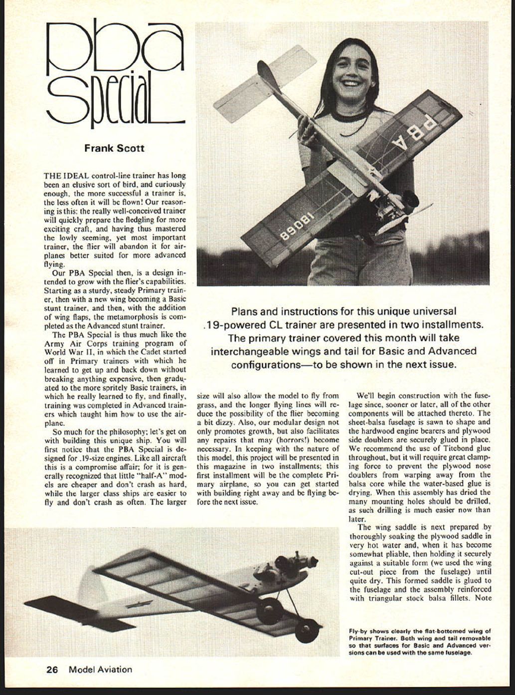
Plans and instructions for this unique universal .19-powered CL trainer are presented in two installments. The primary trainer covered this month will take interchangeable wings and tail for Basic and Advanced configurations—to be shown in the next issue.
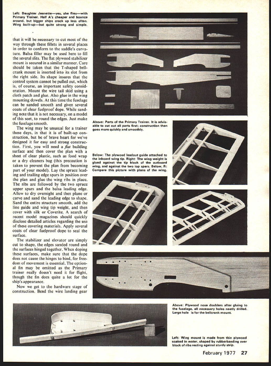
We'll begin construction with the fuselage since, sooner or later, all of the other components will be attached thereto. The sheet-balsa fuselage is sawn to shape and the hardwood engine bearers and plywood side doublers are securely glued in place. We recommend the use of Titebond glue throughout, but it will require great clamping force to prevent the plywood nose doublers from warping away from the balsa core while the water-based glue is drying. When this assembly has dried the many mounting holes should be drilled, as such drilling is much easier now than later.
The wing saddle is next prepared by thoroughly soaking the plywood saddle in very hot water and, when it has become somewhat pliable, then holding it securely against a suitable form (we used the wing cut-out piece from the fuselage) until quite dry. This formed saddle is glued to the fuselage and the assembly reinforced with triangular stock balsa fillets. Note that it will be necessary to cut most of the way through these fillets in several places in order to conform to the saddle's curvature. Balsa filler may be used here to fill the several slits. The flat plywood stabilizer mount is secured in a similar manner. Care should be taken that the T-shaped bellcrank mount is inserted into its slot from the right side. Its shape insures that the control system cannot be pulled out, which is, of course, an important safety consideration. Mount the wire tail skid using a cloth patch and glue. Also glue in the wing mounting dowels. At this time the fuselage can be sanded smooth and given several coats of clear fuelproof dope. While sanding note that it is not necessary, on a model of this sort, to round the edges. Just make the fuselage smooth.
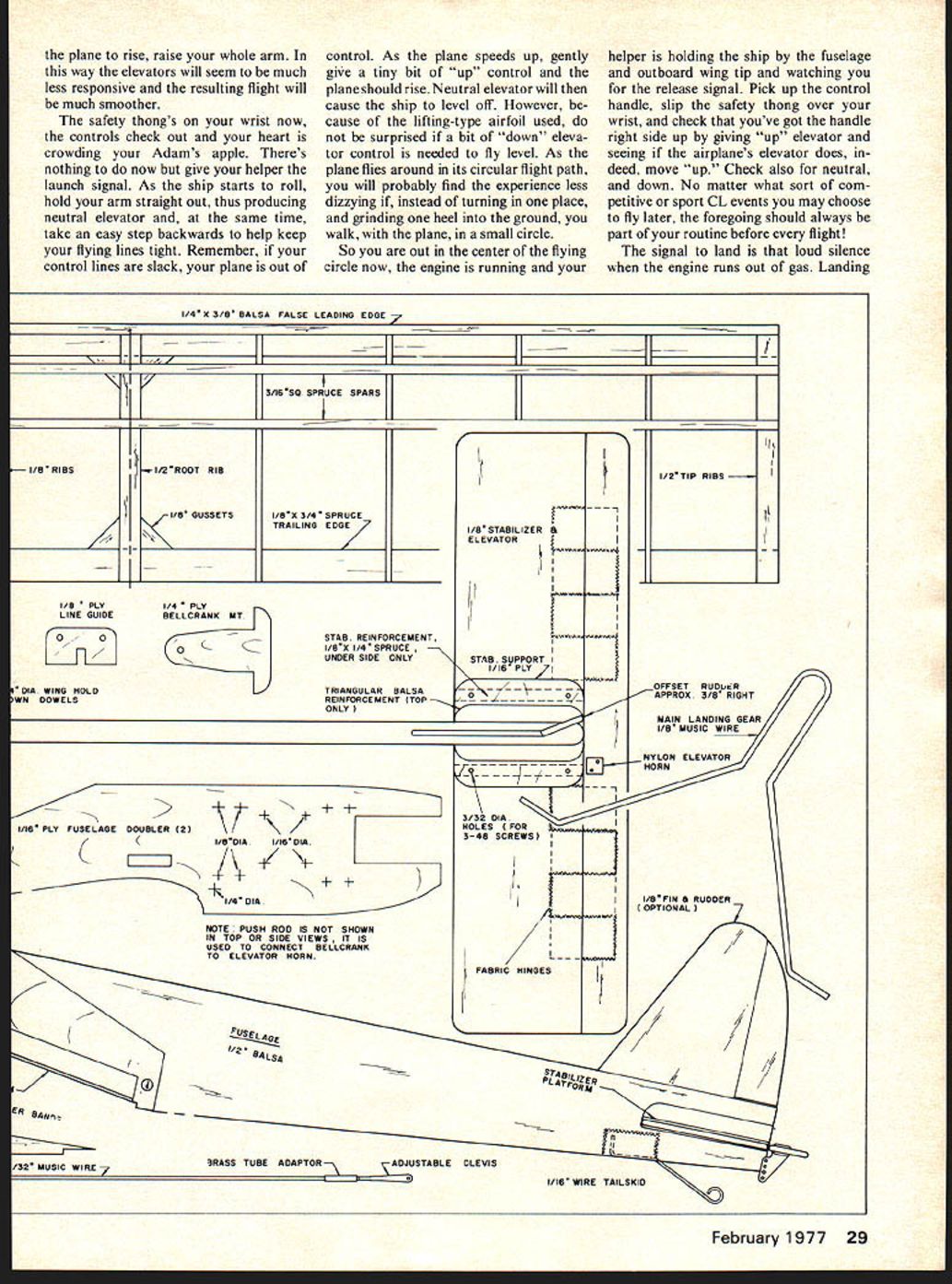
The wing may be unusual for a trainer these days, in that it is of built-up construction, but be of brave heart for we've designed it for easy and strong construction. First, you will need a flat building surface and then cover the plan with a sheet of clear plastic, such as food wrap or a dry cleaners bag (this precaution is taken to prevent the plan from becoming part of your model). Lay the spruce leading and trailing edge spars in position over the plan and glue the wing ribs in place. The ribs are followed by the two spruce upper spars and the balsa leading edge. Allow to dry overnight and then plane or carve and sand the leading edge to shape. Sand the entire structure smooth, add the line guide and wing tip weight, and then cover with silk or Coverite. A search of recent model magazines should quickly disclose detailed articles regarding the use of these covering materials. Apply several coats of clear fuelproof dope to seal the surface.
The stabilizer and elevator are simply cut to shape, the edges sanded round and the surfaces hinged together. When doping these surfaces, make sure that the dope does not cause the hinges to bind, for freedom of movement is essential. The optional fin may be omitted as the Primary trainer really doesn't need it for flight, though the fin does quite a lot for the ship's appearance.
Now we get to the hardware stage of construction. Bend the wire landing gear to shape and secure the wheels in place.
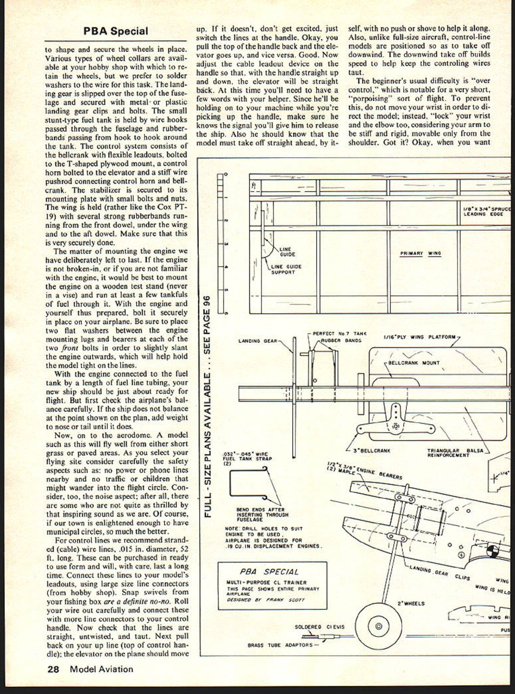
Various types of wheel collars are available at your hobby shop with which to retain the wheels, but we prefer to solder washers to the wire for this task. The landing gear is slipped over the top of the fuselage and secured with metal or plastic landing gear clips and bolts. The small stunt-type fuel tank is held by wire hooks passed through the fuselage and rubberbands passing from hook to hook around the tank. The control system consists of the bellcrank with flexible leadouts, bolted to the T-shaped plywood mount, a control horn bolted to the elevator and a stiff wire pushrod connecting control horn and bellcrank. The stabilizer is secured to its mounting plate with small bolts and nuts. The wing is held (rather like the Cox PT-19) with several strong rubberbands running from the front dowel, under the wing and to the aft dowel. Make sure that this is very securely done.
The matter of mounting the engine we have deliberately left to last. If the engine is not broken-in, or if you are not familiar with the engine, it would be best to mount the engine on a wooden test stand (never in a vise) and run at least a few tankfuls of fuel through it. With the engine and yourself thus prepared, bolt it securely in place on your airplane. Be sure to place two flat washers between the engine mounting lugs and bearers at each of the two front bolts in order to slightly slant the engine outwards, which will help hold the model tight on the lines.
With the engine connected to the fuel tank by a length of fuel line tubing, your new ship should be just about ready for flight. But first check the airplane's balance carefully. If the ship does not balance at the point shown on the plan, add weight to nose or tail until it does.
Now, on to the aerodrome. A model such as this will fly well from either short grass or paved areas. As you select your flying site consider carefully the safety aspects such as: no power or phone lines nearby and no traffic or children that might wander into the flight circle. Consider, too, the noise aspect; after all, there are some who are not quite as thrilled by that inspiring sound as we are. Of course, if our town is enlightened enough to have municipal circles, so much the better.
For control lines we recommend stranded (cable) wire lines, .015 in. diameter, 52 ft. long. These can be purchased in ready to use form and will, with care, last a long time. Connect these lines to your model's leadouts, using large size line connectors (from hobby shop). Snap swivels from your fishing box are a definite no-no. Roll your wire out carefully and connect these with more line connectors to your control handle. Now check that the lines are straight, untwisted, and taut. Next pull back on your up line (top of control handle): the elevator on the plane should move up. If it doesn't, don't get excited, just switch the lines at the handle. Okay, you pull the top of the handle back and the elevator goes up, and vice versa. Good. Now adjust the cable leadout device on the handle so that, with the handle straight up and down, the elevator will be straight back. At this time you'll need to have a few words with your helper. Since he'll be holding on to your machine while you're picking up the handle, make sure he knows the signal you'll give him to release the ship. Also he should know that the model must take off straight ahead, by itself, with no push or shove to help it along.
Also, unlike full-size aircraft, control-line models are positioned so as to take off downwind. The downwind take off builds speed to help keep the controlling wires taut.
The beginner's usual difficulty is "over control," which is notable for a very short, "porpoising" sort of flight. To prevent this, do not move your wrist in order to direct the model; instead, "lock" your wrist and the elbow too, considering your arm to be stiff and rigid, movable only from the shoulder. Got it? Okay, when you want the plane to rise, raise your whole arm. In this way the elevators will seem to be much less responsive and the resulting flight will be much smoother.
The safety thong's on your wrist now, the controls check out and your heart is crowding your Adam's apple. There's nothing to do now but give your helper the launch signal. As the ship starts to roll, hold your arm straight out, thus producing neutral elevator and, at the same time, take an easy step backwards to help keep your flying lines tight. Remember, if your control lines are slack, your plane is out of control. As the plane speeds up, gently give a tiny bit of "up" control and the plane should rise. Neutral elevator will then cause the ship to level off. However, because of the lifting-type airfoil used, do not be surprised if a bit of "down" elevator control is needed to fly level. As the plane flies around in its circular flight path, you will probably find the experience less dizzying if, instead of turning in one place, and grinding one heel into the ground, you walk, with the plane, in a small circle.
So you are out in the center of the flying circle now, the engine is running and your helper is holding the ship by the fuselage and outboard wing tip and watching you for the release signal. Pick up the control handle, slip the safety thong over your wrist, and check that you've got the handle right side up by giving "up" elevator and seeing if the airplane's elevator does, indeed, move "up." Check also for neutral, and down. No matter what sort of competitive or sport CL events you may choose to fly later, the foregoing should always be part of your routine before every flight!
The signal to land is that loud silence when the engine runs out of gas. Landing
THE IDEAL control-line trainer has long eluded the modeler. Curiously enough, successful trainers are less often flown because a really well-conceived trainer will quickly prepare the fledgling for more exciting craft. Having thus mastered a lowly-seeming yet important trainer, the flier will abandon airplanes better suited to advanced flying. The PBA Special is designed to grow a flier's capabilities. Starting as a sturdy, steady Primary trainer, a new wing becomes a Basic stunt trainer; with the addition of wing flaps the metamorphosis is completed — an Advanced stunt trainer.
The PBA Special is much like the Army Air Corps training program of World War II. The cadet started off on Primary trainers, learned to get up, get back down and not break anything expensive; graduated to spritely Basic trainers and really learned to fly; finally, when training was completed, Advanced trainers taught him to use the airplane. So much philosophy — let's get building.
You'll first notice the PBA Special is designed for .19-size engines. Like aircraft, compromise is a fact of life. Generally, it is recognized that little half-A models are cheaper and don't crash hard, while the larger class ships are easier to fly and don't crash as often. The Model Aviation plans and instructions for this unique, universal .19-powered CL trainer are presented in two installments. The Primary trainer was covered last month; this installment will take the airplane to the Basic/Advanced configurations to be shown next issue.
The size will also allow the model to fly off grass; longer flying lines will reduce the possibility of the flier becoming a bit dizzy. Also, the modular design promotes growth and facilitates repairs should horrors become necessary. Keeping the nature of a model project in mind, the airplane will be presented in two installments; the first installment will complete the Primary airplane so you can get started building right away and be flying before the next issue.
We'll begin construction with the fuselage, since sooner or later the other components will be attached thereto. The sheet-balsa fuselage is sawn to shape; hardwood engine bearers and plywood side doublers are securely glued in place. We recommend the use of Titebond glue throughout; it will require great clamping force to prevent the plywood nose doublers from warping away from the balsa core. Because Titebond is water-based, allow the assembly to dry thoroughly before drilling the mounting holes — such drilling is much easier now than later.
The wing saddle is next prepared. Thoroughly soak the plywood saddle in very hot water until it becomes somewhat pliable. Hold it securely against a suitable form of the wing cut-out piece of fuselage until quite dry. The formed saddle is glued to the fuselage assembly and reinforced with triangular stock balsa fillets.
Note: the fly-by shows clearly the flat-bottomed wing of the Primary trainer. Both wing and tail removable surfaces of the Basic/Advanced versions can use the same fuselage.
The wing is built up, but is quite strong and simple. It will be necessary to cut away the fillets in several places in order to conform to the saddle's curvature. Balsa filler may be used to fill several slits. The flat plywood stabilizer mount is secured in a similar manner.
Care should be taken that the T-shaped bellcrank mount is inserted into its slot on the right side. Its shape insures the control system cannot be pulled out — of course an important safety consideration. Mount the wire tail skid using a cloth patch and glue. Also glue the wing mounting dowels in place at this time. The fuselage can be sanded smooth and given several coats of clear, fuelproof dope. Sanding is not necessary to round every edge — just make the fuselage smooth.
The wing may be of the unusual trainer days' built-up construction, but we've designed it for easy, strong construction. First, you will need a flat building surface. Cover the plan sheet with clear plastic such as food wrap or a dry-cleaners' bag. This precaution is taken to prevent the plan from becoming part of the model.
Lay the spruce leading and trailing edge spars in position over the plan and glue the wing ribs in place, followed by the two spruce upper spars and the balsa leading edge. Allow to dry overnight. Plane, carve and sand the leading edge to shape. Sand the entire structure smooth. Add the line-guide and wing tip weight, then cover with silk or Coverite. Recent model magazines contain detailed articles regarding the use of covering materials; consult them as needed. Apply several coats of clear, fuelproof dope to seal the surface.
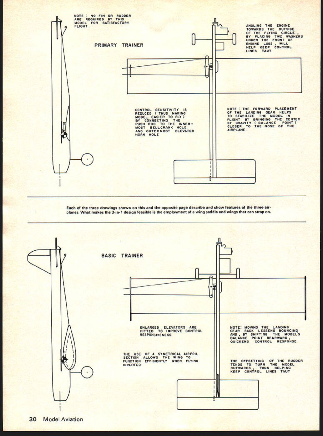
The stabilizer and elevator are simply cut to shape, the edges sanded and rounded, the surfaces hinged t NOTE: NO FIN OR RUDDER ARE REQUIRED BY THIS MODEL FOR SATISFACTORY FLIGHT.
PRIMARY TRAINER
CONTROL SENSITIVITY IS REDUCED (THUS MAKING MODEL EASIER TO FLY) BY CONNECTING THE PUSH ROD TO THE INNERMOST BELLCRANK HOLE AND OUTERMOST ELEVATOR HORN HOLE
ANGLING THE ENGINE TOWARDS THE OUTSIDE OF THE FLYING CIRCLE, BY PLACING TWO WASHERS UNDER THE FRONT OF ENGINE LUGS, WILL HELP KEEP CONTROL LINES TAUT
NOTE: THE FORWARD PLACEMENT OF THE LANDING GEAR HELPS TO STABILIZE THE MODEL IN FLIGHT BY BRINGING THE CENTER OF GRAVITY (BALANCE POINT) CLOSER TO THE NOSE OF THE AIRPLANE.
Each of the three drawings shown on this and the opposite page describe and show features of the three airplanes. What makes the 3-in-1 design feasible is the employment of a wing saddle and wings that can strap on.
BASIC TRAINER
ENLARGED ELEVATORS ARE FITTED TO IMPROVE CONTROL RESPONSIVENESS
THE USE OF A SYMMETRICAL AIRFOIL SECTION ALLOWS THE WING TO FUNCTION EFFICIENTLY WHEN FLYING INVERTED
NOTE: MOVING THE LANDING GEAR BACK LESSENS BOUNCING AND, BY SHIFTING THE MODEL'S BALANCE POINT REARWARD, QUICKENS CONTROL RESPONSE
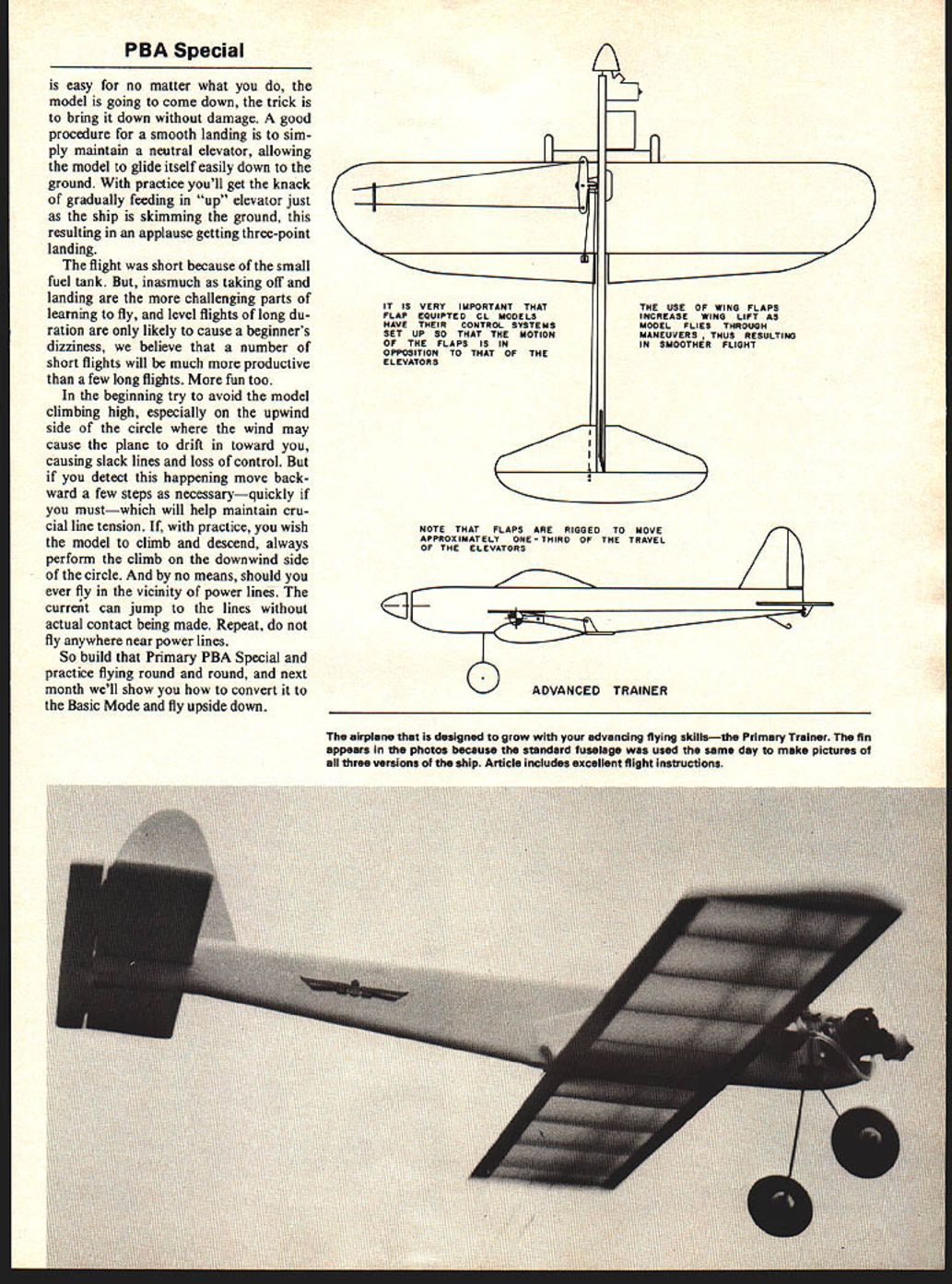
THE OFFSETTING OF THE RUDDER TENDS TO TURN THE MODEL OUTWARDS THUS HELPING KEEP CONTROL LINES TAUT is easy for no matter what you do, the model is going to come down, the trick is to bring it down without damage. A good procedure for a smooth landing is to simply maintain a neutral elevator, allowing the model to glide itself easily down to the ground. With practice you'll get the knack of gradually feeding in "up" elevator just as the ship is skimming the ground, this resulting in an applause-getting three-point landing.
The flight was short because of the small fuel tank. But, inasmuch as taking off and landing are the more challenging parts of learning to fly, and level flights of long duration are only likely to cause a beginner's dizziness, we believe that a number of short flights will be much more productive than a few long flights. More fun too.
In the beginning try to avoid the model climbing high, especially on the upwind side of the circle where the wind may cause the plane to drift in toward you, causing slack lines and loss of control. But if you detect this happening move backward a few steps as necessary—quickly if you must—which will help maintain crucial line tension. If, with practice, you wish the model to climb and descend, always perform the climb on the downwind side of the circle. And by no means should you ever fly in the vicinity of power lines. The current can jump to the lines without actual contact being made. Repeat, do not fly anywhere near power lines.
So build that Primary PBA Special and practice flying round and round, and next month we'll show you how to convert it to the Basic Mode and fly upside down.
Transcribed from original scans by AI. Minor OCR errors may remain.

