
Peanut S.E. 5a
Edward F. Fort
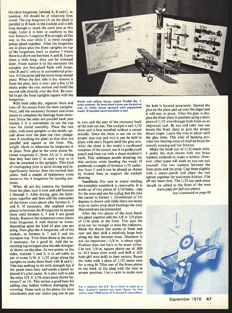
THE S.E. 5a is often modeled in rubber-powered free-flight scale and for good reason. With its low aspect ratio it provides lots of wing area for a given span, its nose is reasonably long and its straight lines simplify construction. In Peanut Scale, where span is limited to 13 in., an S.E. 5a turns out to be a relatively large model in which all of its advantages can be put to good use.
Fuselage: Construction is slightly different from conventional practices but is not difficult. Primary areas of difference are in the placement of the uprights and the use of three longerons for the basic fuselage sides. Forward of the cockpit the uprights are inset from the longerons while in the after section they are flush. As shown in the top view, upper cross pieces are sheet formers — lower ones are 1/16 sq. strips.
After covering the plan with plastic or waxed paper, start construction by fixing the basic fuselage sides. the three longerons; labeled A, B and C; in position. All should be of relatively firm wood. The top longeron (A on the plan) is parallel to B back to the cockpit and is left long enough to reach the stern post at this stage. Later it is bent to conform to the rear formers. Longeron B is straight all the way to the rear while C is three straight pieces glued together. After the longerons are in place glue the front uprights on top of the longerons, back to station 5 where there is a short one between A and B. Leave them a little long—they can be trimmed later. From station 6 to the sternpost the uprights are butt-glued flush with longerons B and C only as in conventional practice. At this point add the lower wing-mount plate. When the first side is dry remove it from the plan, turn it over, put a few 1/16 shims under the rear section and build the second side directly over the first. Be careful to get the front uprights square with the longerons.
With both sides dry, separate them and trim off the excess from the inset uprights. Next, add the necessary formers and cross pieces to complete the fuselage basic structure. Since the sides are parallel back past station 5 it is convenient to use the top view for initial assembly. Place the two sides, with inset uprights to the inside, upside down over the plan top view (longerons A touching the plan) so that they are parallel and square at the front. Pin, weight, block or otherwise fix longerons A in place. Now glue in the cross pieces between longerons C, from 1A to 5, noting that they butt into C in such a way as to also be attached to the uprights. This kind of overlapping joint is quite strong and insignificantly heavier than the normal butt joints. Add a couple of temporary cross pieces to the A longerons for spacing purposes.
When all are dry remove the fuselage from the plan, turn it over and add formers 1 through 5. After drying, glue the sternposts together and then add the remainder of the lower cross pieces plus formers 6, 7 and 8. If necessary, slip unglued cross pieces in between the B longerons to spread them until formers 6, 7 and 8 are glued firmly. Remove the temporary cross pieces from longerons A with a thinner or water, depending upon the kind of glue you are using. Now glue the A longerons, aft of the cockpit, to formers 6, 7, 1 and 8 and the sternpost top. Trim them down at the rear, if necessary, for a good fit. Add the remaining top stringers plus the side stringers as shown on the plan. At two points on the sides, stations 3 and 5, it is advisable to put in some 1/16 x 1/32 strips along the uprights to make them flush with B and C. This has nothing to do with strength but if the paper tears later and needs a panel replaced it's a lot easier. It is also well to add the extra 1/8 x 1/16 cross piece shown between C at 1A. This makes a good base for adding clay ballast without damaging the covering. Items such as the plates for strut attachment and rear motor peg can be put in now and the part of the sternpost back of the stab cut out. The cockpit is soft 1/32 sheet and is best installed without a cutout initially. Once the sheet is cut out to the proper size (cut and try) it can be held in place with one's fingers until the glue sets. After the sheet is dry make a cardboard template of the cutout, use it to guide a soft pencil and then cut with a sharp modeler's knife. This technique avoids breaking the thin sections while bending the wood. If preferred, a couple of formers 1/32 undersize from 5 and 6 can be placed as shown by broken lines to support the cockpit sheeting.
Noseblock: For ease in motor winding the complete noseblock is removable. It is made up of two pieces of 3/16 balsa—one for the nose and one for a plug that fits into the cutout in former 1. Downthrust of 2 1/2 degrees is shown and while there are many ways to make prop shaft bushings the ones illustrated are recommended.
After the two pieces of the nose block are glued together add the 3/8 x 3/8 plate or 1/16 sheet at the front. This puts the prop out far enough to miss the radiators. Mark the thrust line points at front and rear and then drill a relatively large hole along the line between them. Diameter is not too important—1/8 in. is about right. Position does not have to be exact either. Cut two 1/4-in. square plates out of .008 to .012 brass shim stock and drill a .032 hole (#67 wire drill) in their centers. Ream the holes with a piece of 1/32 music wire for a snug fit. Glue one of the brass plates to the back of the plug with the hole in proper position. Use a ruler to make sure the hole is located accurately. Spread the glue on the front plate and up over the edges and it will stay in place. After the glue is dry, glue the front plate in position using a short piece of 1/32 wire through both holes as an alignment tool. By eye and ruler one can locate the front plate to give the proper thrust angle. Leave the wire in place until the glue dries. This kind of bushing provides low bearing areas of steel on brass for smooth running and low friction.
Make the hook out of 1/32 music wire. I prefer the style shown with two brass washers soldered to make a bobbin. However, other types will work so you can suit yourself. Use two washers between the front plate and the prop. Cut shaft spline with a center-punch and place the two axles together for minimum friction. File off any burrs first. The 1/32 top tank piece should be added to the front of the nose block.
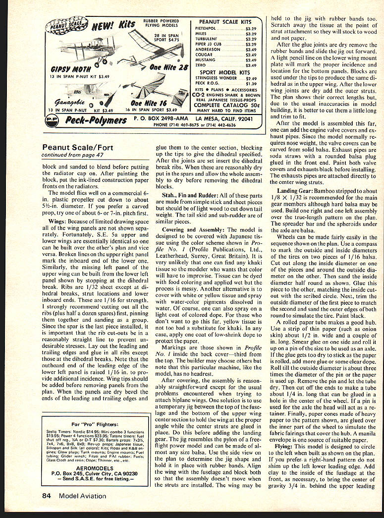
After the noseblock is complete, assemble and mount the landing gear and strut fittings as shown on the plan. Balance the model on the points shown and add clay ballast where required for proper trim. Covering may be done with colored or food-dyed tissue; if painted, some duration is lost. For a biplane the S.E. 5a is hard to beat as a flier. Author's model has been flown for five years, uses 1500 turns of 2-strand 2-mm rubber.
Peanut S.E. 5a
block and sanded to blend before putting the radiator cap on. After painting the block, put the ink-lined construction paper fronts on the radiators.
The model flies well on a commercial 6-in. plastic propeller cut down to about 5-1/2-in. diameter. If you prefer a carved prop, try one of about 6- or 7-in. pitch first.
Wings: Because of the limited drawing space all of the wing panels are not shown separately. Fortunately, the S.E. 5a upper and lower wings are essentially identical so one can be built over the other’s plan and vice versa. Broken lines in the upper right panel mark the inboard end of the lower wing. Similarly, the missing left panel of the upper wing can be built from the lower left panel shown by stopping at the dihedral break. Ribs are 1/32 sheet except at dihedral breaks, strut locations and lower inboard ends. These are 1/16 for strength. I strongly recommend cutting out all the ribs (plus half a dozen spares) first, pinning them together and sanding as a group. Since the spar is the last piece installed, it is important that the rib cut-outs be in a reasonably straight line to prevent undesirable stresses. Lay out the leading and trailing edges and glue in all ribs except those at the dihedral breaks. Note that the outboard end of the leading edge of the lower left panel is raised 1/16 in. to provide additional incidence. Wing tips should be added before removing panels from the plan. When the panels are dry bevel the ends of the leading and trailing edges and glue them to the center section, blocking up the tips to give the dihedral specified. After the joints are set insert the dihedral break ribs. When these are reasonably dry put in the spars and allow the whole assembly to dry before removing the dihedral blocks.
Stab., Fin and Rudder:
All of these parts are made from simple stick and sheet pieces but should be of light wood to cut down tail weight. The tail skid and sub-rudder are of small pieces.
Covering and Assembly:
The model is designed to be covered with Japanese tissue using the color scheme shown in Profile No. 1 (Profile Publications, Ltd., Leatherhead, Surrey, Great Britain). It is very unlikely that one can find any khaki tissue so the modeller who wants that color will have to improvise. Tissue can be dyed with food coloring and applied wet but the process is messy. Another alternative is to cover with white or yellow tissue and spray with water-color pigments dissolved in water. Of course, one can also spray on a light coat of colored dope. For those who don't want to go this far, yellow tissue is not bad a substitute for khaki. In any case, apply one coat of low-shrink dope to protect the paper.
Markings are those shown in Profile No. 1 inside the back cover—third from the top. The builder may choose others but note that this particular machine, like the model, has no headrest.
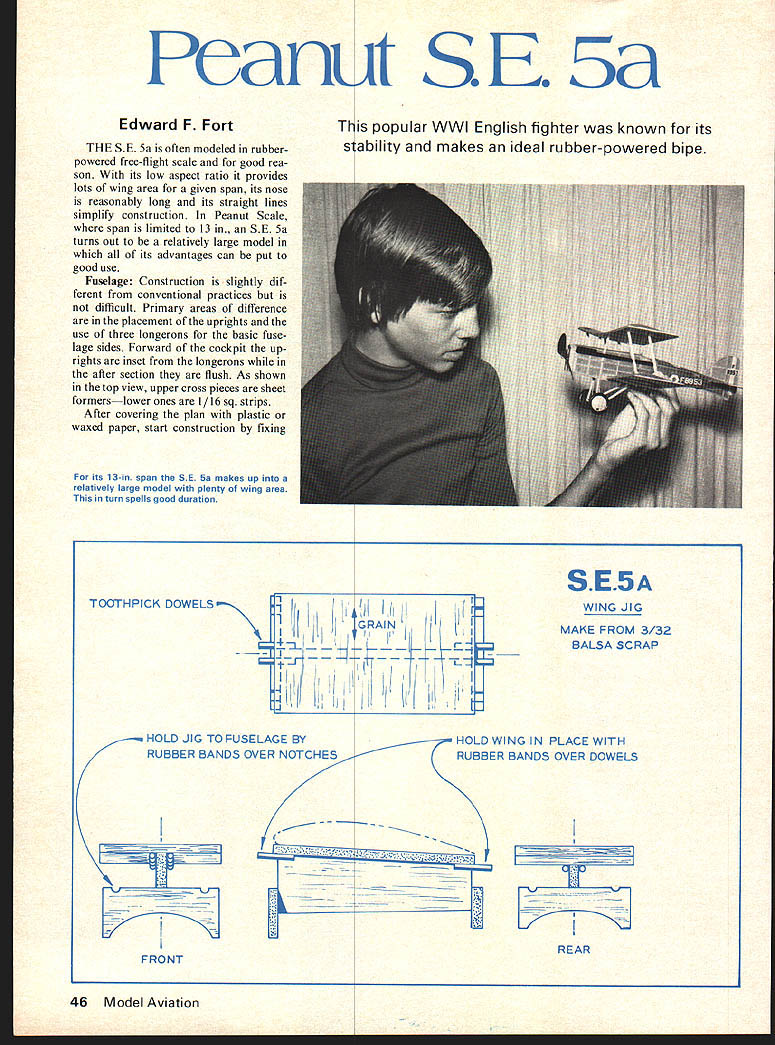
After covering, the assembly is reasonably straightforward except for the usual problems encountered when trying to attach biplane wings. One solution is to use a temporary jig between the top of the fuselage and the bottom of the upper center section to hold the wing at the proper angle while the center struts are glued in place. Do this before adding the landing gear. The jig resembles the pylons of a free-flight power model and can be made of almost any size balsa. Use the side view on the plan to determine the jig shape and hold it in place with rubber bands. Align the wing with the fuselage and block both so that the assembly doesn't move when the struts are installed. The wing may be held to the jig with rubber bands too. Scratch away the tissue at the point of strut attachment so they will stick to wood and not paper.
After the glue joints are dry remove the rubber bands and slide the jig out forward. A light pencil line on the lower wing mount plate will mark the proper incidence and location for the bottom panels. Blocks are used under the tips to produce the same dihedral as in the upper wing. After the lower wing joints are dry add the outer struts. The plan shows their correct lengths but, due to the usual inaccuracies in model building, it is better to cut them a little long and trim to fit.
After the model is assembled this far, one can add the engine valve covers and exhaust pipes. Since the model normally requires nose weight, the valve covers can be carved from solid balsa. Exhaust pipes are soda straws with a rounded balsa plug glued in the front end. Paint both valve covers and exhausts black before installing. The exhausts pipes are attached directly to the center wing struts.
Landing Gear:
Bamboo stripped to about 1/8 x 3/32 is recommended for the main gear members although hard balsa may be used. Build one right and one left assembly over the true-length pattern on the plan. The spreader bar and the spheroids under the axle are balsa.
Wheels can be made fairly easily in the sequence shown on the plan. Use a compass to mark the outside and inside diameter of the tires on two pieces of 1/16 balsa. Cut out along the inside diameter on one of the pieces and around the outside diameter on the other. Then sand the inside diameter half-round as shown. Glue this piece to the other, matching the inside cut with the scribed circle. Next, trim the outside diameter of the first piece to match the second and sand the outer edges of both round to approximate the tire. Paint black. A rolled paper tube makes a good hub. Use a strip of thin paper (such as onion skin) about 1/2 in. wide and a couple of drops of glue on one side and roll it up on a pin of the desired size to be used as an axle. If the glue gets too dry to stick as the paper is rolled, add more glue or some clear dope. Roll the outside diameter about three times the diameter of the pin or until the paper is used up. Remove the pin and roll the tube dry. Then cut off the ends to make a tube about 1/4 in. long that can be glued in the hole in the center of the wheel. If a pin is used for the axle the head will act as a retainer. Finally, paper cones made of heavy paper to the pattern shown are glued over the inner part of the wheel to simulate the fabric fairings that cover the hub. A manila envelope is one source of suitable paper.
Flying:
This model is designed to circle to the left when properly trimmed. If you prefer a right-hand pattern do not shim the left lower leading edge. Add clay to the inside of the fuselage at the front, as necessary, to bring the center of gravity 3/4 in. behind the upper leading edge. A two-strand motor of 2-mm rubber about 19 in. long works well. Put in about 1,000 turns and allow the model to ROG. If it flies straight ahead and stalls, bend the rudder over for a left turn. If stalling persists, bend the stabilizer trailing edge down. Remember that tightening up a left turn will help convert a stall into a spiral climb and reduce the need for more down-thrust or stabilizer force during the initial power burst. When the model is adjusted to climb in a smooth left turn without stalling, add a few more turns — my normal maximum is about 1,500. The model should take off, make a fairly steep climb to the left, nearly stall but roll out and proceed into a shallow left climb. If the stall is too severe, the rudder turn is too tight; bend the stabilizer down more or add more down-thrust with a shim behind the top of the nose block.
If, on the initial flights, the model refuses to climb but rather flies in a tight left circle, open up the turn with the rudder. If climb is still poor, remove some of the ballast clay and consider yourself lucky. Stalling is the more probable difficulty. The additional incidence built into the lower left wing should hold it up during turns. However, if it doesn't, add a small trim tab.
The prototype model is nearly five years old now and has provided a lot of enjoyable flying, competitive as well as just for fun. I hope yours does the same for you.
Transcribed from original scans by AI. Minor OCR errors may remain.

