
Pegasus
Stan Watson
BIGGER is better! At least that's what they say. But for what? We've seen FAI RC soaring models getting smaller and smaller year by year, and the most recent crop is clearly "better" at speed, distance and even duration. So, bigger is not necessarily better. What matters is the flier's objectives for any given design, as well as the rules for an event he may wish to enter. Finally, a person may wish to build a soaring model which will suit his own ideas of what is best, and let the "rules" be for those who wish to be bound by them.
The Pegasus began as a design concept which finally began to take shape in January 1978. My objective was to seek higher L.S.F. requirements with an aircraft that would be capable of setting altitude, distance and duration records. I was also terribly impressed by the sweep and beauty of the large models in flight, and couldn't wait until I could also fly one. I wanted a model that would do well in contests, including spot landings, because I was really involved in L.S.F. achievement. I also wanted a fiberglass fuselage and bladed wings for simplicity, strength and rigidity.
Pegasus first flew in May 1978. The second model was improved with flaps, sheeting and a bit of "Phillips entry" cranked into the airfoil to improve high-speed characteristics.
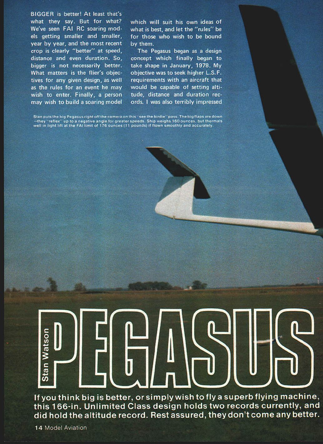
Stan puts the big Pegasus right off the camera on this "see the birdie" pass. The big flaps are down—they "reflex" up to a negative angle for greater speeds. Ship weighs 160 ounces, but it thermals well in light lift at the FAI limit of 176 ounces (11 pounds) if flown smoothly and accurately.
If you think big is better, or simply wish to fly a superb flying machine, this 166-inch Unlimited Class design holds two records currently, and did hold the altitude record. Rest assured, they don't come any better.
Further modification will occur by those who wish to tailor the characteristics to suit their own needs, and who feel that they are familiar enough with large models to take the risks involved in making such changes. One modification to make the model more suited to fast cross-country flight (but less for altitude flight) would be to thin the wings toward the tips—one or two percent at the polyhedral break and another percent or two at the tip. "Stretching" the tip panels would enhance the scale-like flight appearance at the penalty of more difficult spot landings. The model as shown is rock steady and modifications, if carefully thought out, should not be too risky.
General Description
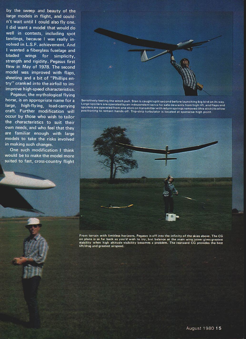
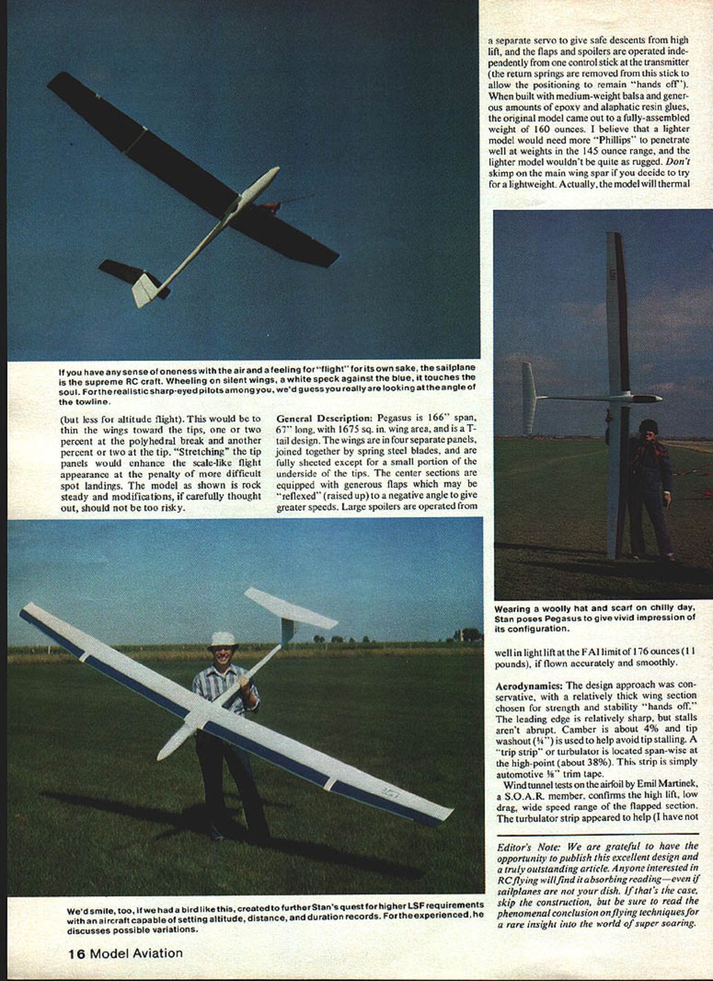
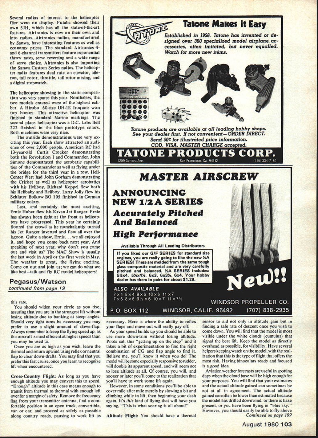
Pegasus is a 166" span, 67" long, T-tail design with 1,675 sq. in. wing area. The wings are in four separate panels joined by spring steel blades and are fully sheeted except for a small portion of the underside of the tips. The center sections are equipped with generous flaps which may be "reflexed" (raised up) to a negative angle to give greater speeds. Large spoilers are operated from a separate servo to give safe descents from high lift. The flaps and spoilers are operated independently from one control stick at the transmitter (the return springs are removed from this stick to allow the positioning to remain "hands off").
When built with medium-weight balsa and generous amounts of epoxy and aliphatic resin glues, the original model came out to a fully assembled weight of 160 ounces. I believe a lighter model would need more "Phillips" to penetrate well at weights in the 145-ounce range, and the lighter model wouldn't be quite as rugged. Don't skimp on the main wing spar if you decide to try for a lightweight. The model will thermal well in light lift at the FAI limit of 176 ounces (11 pounds), if flown accurately and smoothly.
Specifications:
- Span: 166"
- Length: 67"
- Wing area: 1,675 sq. in.
- Configuration: T-tail, four-panel wing with spring-steel blade joiners
- Typical assembled weight: ~160 oz.
Aerodynamics
The design approach was conservative, with a relatively thick wing section chosen for strength and stability—"hands off." The leading edge is relatively sharp, but stalls aren't abrupt. Camber is about 4% and tip washout (1/4°) is used to help avoid tip stalling. A "trip strip" or turbulator is located span-wise at the high point (about 38% chord). This strip is simply automotive 3/4" trim tape.
Wind tunnel tests on the airfoil by Emil Martinek, a S.O.A.R. member, confirm the high lift, low drag and wide speed range of the flapped section. The turbulator strip appeared to help (I have not yet tried the model without it). The tail surfaces are relatively thick and give good tail volume, providing lots of stability and control with only a slight penalty in drag. A smaller, thinner horizontal stabilizer would be preferable for modelers interested in all-out cross-country flight.
The CG shown on the plans is probably as far to the rear as you may wish to try; a balance point at the main wing joiner will give the greatest stability at the highest altitudes when visibility becomes a problem. The rearward CG will give the best L/D and greatest speed.
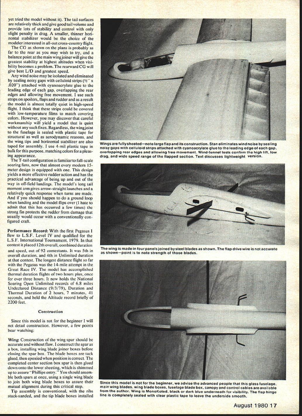
Any wind noise may be isolated and eliminated by sealing noisy gaps with celluloid strips (1/2" x .020") attached with cyanoacrylate glue to the leading edge of each gap, overlapping the rear edges and allowing free movement. I use such strips on spoilers, flaps and rudder and as a result the model is almost totally quiet in high-speed flight. These strips could be covered with low-temperature films to match covering colors. The wing joint to the fuselage is sealed with plastic tape for structural as well as aerodynamic reasons, and the wing tips and horizontal stabilizer are also taped for assembly. I use 4-mil plastic tape in bulk for this purpose, matching colors for a pleasing appearance.
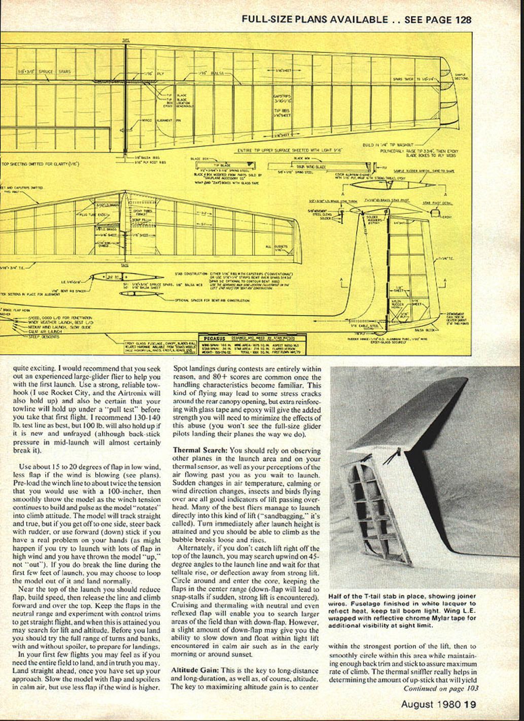
The T-tail configuration, familiar to full-scale soaring fans and common on modern 15-meter designs, yields more effective rudder action and has the practical advantage of being up and out of the way in off-field landings. The model's long tail moment arm gives arrow-straight launches and a relatively quick response when turns are made. If you happen to ground-loop and the model flips over, the strong fin protects the rudder from damage that usually would occur with a conventional configuration.
Performance Record
With the first Pegasus I flew to L.S.F. Level IV and qualified for the L.S.F. International Tournament, 1979. In that contest it placed 12th overall (combined duration and speed) out of 92 contestants. It was 5th in overall duration, and 4th in Unlimited duration at that contest.
Notable flights and records:
- Longest distance: 14 miles (Great Race IV)
- Thermal duration: over three hours on one flight; two hours plus on multiple flights
- National Soaring Open Unlimited records: 6.8 miles undeclared distance (9/3/79), duration and thermal duration of 2:07:41
- Briefly held altitude record of 2,200 feet
Construction
This model is not for the beginner; I will not detail every step. However, a few important points bear watching.
Wing
- Construct the wing spar accurately and without flaw. I build the spar as a box, installing wing blade joiner boxes before closing the spar box. The blade boxes are tack-glued, then epoxied when the position is correct.
- Glue the completed center section box spar down onto the lower sheeting, which is shimmed up to assure "Phillips entry." Assemble both spars at once, using a single wing blade to join both wing blade boxes to assure mutual alignment during this critical step.
- Tip assembly is conventional, with ribs stack-sanded and tip blade boxes installed in each tip. These boxes are notched to accept the joiner blades which are mounted in the center of the boxes.
- I used .062" spring steel blades, which must be sanded and painted to prevent corrosion. Keep alignment perfect when gluing the tip blade boxes.
- Install the flaps and ailerons, making sure hinge gaps are minimized. The flap hinge line should be completely sealed with clear plastic tape to leave the underside smooth.
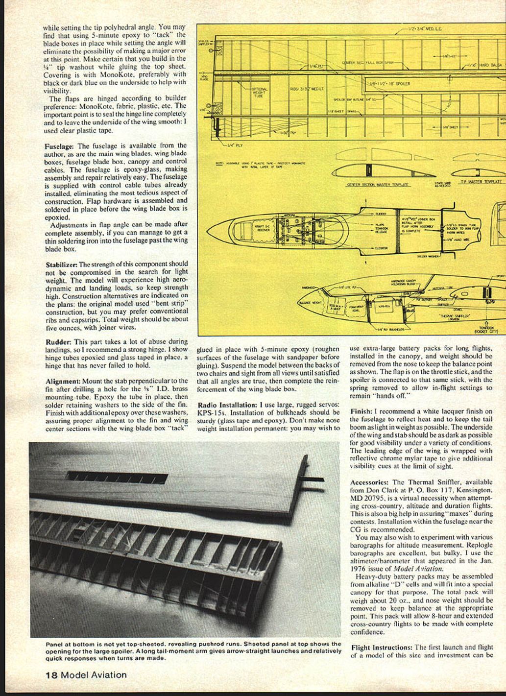
- When setting the tip polyhedral angle you may find that using 5-minute epoxy to "tack" the blade boxes in place will eliminate the possibility of a major error. Make certain you build in the 1/4" tip washout while gluing the top sheet.
- Covering is with MonoKote, preferably with black or dark blue on the underside to help with visibility.
- Flaps may be hinged according to builder preference (MonoKote, fabric, plastic, etc.). The important point is to seal the hinge line completely and to leave the underside of the wing smooth (I used clear plastic tape).
Fuselage
- The fuselage, main wing blades, wing blade boxes, fuselage blade box, canopy and control cables are available from the author.
- The fuselage is epoxy-glass, making assembly and repair relatively easy. It is supplied with control cable tubes already installed, eliminating one of the most tedious aspects of construction.
- Flap hardware is assembled and soldered in place before the wing blade box is epoxied.
- Adjustments in flap angle can be made after complete assembly if you can manage to get a thin soldering iron into the fuselage past the wing blade box.
Stabilizer
- Do not compromise strength in the search for light weight. The model will experience high aerodynamic and landing loads.
- Construction alternatives are indicated on the plans: the original model used "bent strip" construction, but you may prefer conventional ribs and capstrips.
- Total stabilizer weight should be about five ounces, with joiner wires.
Rudder
- The rudder takes a lot of abuse during landings. I recommend a strong hinge.
- I show hinge tubes epoxied and glass-taped in place—a hinge that has never failed to hold.
Alignment
- Mount the stabilizer perpendicular to the fin after drilling a hole for a 1/8" I.D. brass mounting tube. Epoxy the tube in place, then solder retaining washers to the side of the fin.
- Finish with additional epoxy over these washers, assuring proper alignment to the fin and wing center sections with the wing blade box "tack" glued in place with 5-minute epoxy. Roughen fuselage surfaces with sandpaper before gluing.
- Suspend the model between the backs of two chairs and sight from all views until satisfied that all angles are true, then complete the reinforcement of the wing blade box.
Radio Installation
- I use large, rugged servos: KPS-15s. Installation of bulkheads should be sturdy (glass tape and epoxy).
- Don't make nose weight installation permanent: you may wish to use extra-large battery packs for long flights, installed in the canopy, and weight should be removed from the nose to keep the balance point as shown.
- The flap is on the throttle stick, and the spoiler is connected to that same stick with the spring removed to allow in-flight settings to remain "hands off."
Finish
- I recommend a white lacquer finish on the fuselage to reflect heat and to keep the tail boom as light in weight as possible.
- The underside of the wing and stabilizer should be as dark as possible for good visibility under a variety of conditions.
- The leading edge of the wing is wrapped with reflective chrome mylar tape to give additional visibility cues at the limit of sight.
Accessories
- The Thermal Sniffer, available from Don Clark at P.O. Box 117, Kensington, MD 20795, is a virtual necessity when attempting cross-country, altitude and duration flights. Installation within the fuselage near the CG is recommended.
- You may also wish to experiment with various barographs for altitude measurement. Replica barographs are excellent, but bulky. I use the altimeter/barometer that appeared in the Jan. 1976 issue of Model Aviation.
- Heavy-duty battery packs may be assembled from alkaline "D" cells and will fit into a special canopy for that purpose. The total pack will weigh about 20 oz.; nose weight should be removed to keep balance at the appropriate point. This pack will allow 8-hour and extended cross-country flights with confidence.
Flight Instructions
The first launch and flight of a model of this size and investment can be quite exciting. Seek out an experienced large-glider flier to help with the first launch. Use a strong, reliable tow-hook (I use Rocket City; the Airtronix will also hold up) and be certain your towline will hold up under a "pull test" before that first flight. I recommend 130–140 lb. test line as best, but 100 lb. will also hold up if it is new and unfrayed (though back-stick pressure in mid-launch will almost certainly break it).
- Use about 15° to 20° of flap in low wind; use less flap if the wind is blowing (see plans).
- Pre-load the winch line to about twice the tension that you would use with a 100-incher, then smoothly throw the model as the winch tension continues to build and pause as the model "rotates" into climb attitude.
- The model will track straight and true, but if you get off to one side, steer back with rudder, or use forward (down) stick if you have a real problem (as might happen if you try to launch with lots of flap in high wind and you have thrown the model "up," not "out").
- If you break the line during the first few feet of launch, you may loop the model out of it and land normally.
Near the top of the launch you should reduce flap, build speed, then release the line and climb forward and over the top. Keep the flaps in the neutral range and experiment with control trims to get straight flight; when this is attained you may search for lift and altitude. Before landing, try the full range of turns and banks, with and without spoilers, to prepare for landings. In your first few flights you may feel as if you need the entire field to land, and in truth you may. Land straight ahead once you have set up your approach. Slow the model with flap and spoilers in calm air, but use less flap if the wind is higher.
Spot landings during contests are entirely within reason, and 80+ scores are common once the handling characteristics become familiar. This kind of flying may lead to some stress cracks around the rear canopy opening, but extra reinforcing with glass tape and epoxy will give the added strength you need to minimize the effects of this abuse.
Thermal Search
Rely on observing other planes in the launch area and on your thermal sensor, as well as your perceptions of the air flowing past you while you wait to launch. Sudden changes in air temperature, calming or wind direction changes, insects and birds flying over are all good indicators of lift passing overhead. Many of the best fliers manage to launch directly into this kind of lift ("sandbagging"). Turn immediately after launch height is attained and you should be able to climb as the bubble breaks loose and rises.
If you don't catch lift right off the top of the launch, search upwind on 45-degree angles to the launch line and wait for that telltale rise or deflection away from strong lift. Circle around and enter the core, keeping the flaps in the center range (down-flap will lead to snap-stalls if sudden, strong lift is encountered). Cruising and thermalling with neutral and even reflexed flap will enable you to search larger areas of the field than with down-flap. However, a slight amount of down-flap may give you the ability to slow down and float within light lift encountered in calm air such as early morning or around sunset.
Altitude Gain
Altitude is the key to long-distance and long-duration flights. The key to maximizing altitude gain is to center within the strongest portion of the lift, then to smoothly circle within this area while maintaining enough back trim and stick to assure maximum rate of climb. The thermal sniffer really helps in determining the amount of up-stick that will yield maximum rate of climb.
You should widen your circle as you rise, assuring that you are in the strongest lift without losing altitude due to steep banking. If very tight turns are necessary you may prefer to use a slight amount of down-flap. Always remember to keep the flying speed up, as this aircraft is most efficient at higher speeds than you may be used to.
Once you are as high as you wish, leave the thermal and return upwind using reflex or neutral flap to clear down-drafts. You may prefer this fast cruise once you learn to recognize lift when encountered.
Cross-Country Flight
As long as you have enough altitude you may convert this to speed. "Enough" altitude means enough to transit from thermal to thermal with a margin of safety. Remove the frequency flag from your transmitter antenna, find a comfortable position in an open truck, convertible, van or car, and proceed as safely as possible along country roads, pausing to work lift as necessary. Here is where the ability to reflex your flaps and move out will really pay off.
As your speed builds you should be able to use more down-trim without losing altitude. Pilots call this "getting up on the step" and it takes a bit of experimentation to find the right combination of CG and flap angle to find it. The model will become especially responsive to rudder, will double its apparent speed, and will seem not to lose altitude at all. Of course you will lose altitude eventually, and sooner or later you'll have to work some lift again.
In some conditions you'll be able to cover mile after mile by slowing a bit and climbing while in lift, then beginning your dash again. It's this kind of flying that makes soaring so satisfying.
Altitude Flight
Use a thermal sensor to aid not only in altitude gain but also in finding a safe rate of descent once you wish to come down. The model is most visible under white cumulus clouds that signal the best lift; keep the model as directly overhead as possible for visibility. Have several helpers keeping watch on the model, and have binoculars ready and focused.
Aviation weather forecasts are useful in spotting days when the cloud base will be high enough for your purposes. You should easily be able to fly above 3,000 feet and, with care, into the 4,000-ft range. The present AMA altitude record is 3,400 feet in Unlimited, held by Jack Hiner, and the World (FAI) altitude record is 4,988 feet. One S.O.A.R. member, John Dineen, holds the AMA National record in 2-meter with a flight of 2,050 feet—showing what could be accomplished by a model the size of Pegasus.
Remember, according to FAI rules the total all-up weight of the model cannot exceed 11 pounds. You may find (as does Jack Hiner) that launching with the "Noon Balloon" and climbing with cloud bases as the afternoon progresses is the best way to reach really high altitudes. Locating the CG at the main wing blade is the safest, most stable position for altitude flight.
Conclusion
Much of the preceding advice can be applied to all soaring models, but I have found it applies especially to large models best suited to flying high and far. My thanks go to Jack Hiner for his advice in flying the model, to John Dineen for his help with laying up the original fuselage, and to other S.O.A.R. members for their cooperation and support. Last, and of course not least, my appreciation must go to both my wife and mother, who over the years have put up with much of the mess and bother associated with this hobby and yet are still capable of showing enthusiasm when a new project takes to the sky.
Transcribed from original scans by AI. Minor OCR errors may remain.

