
Peregrine
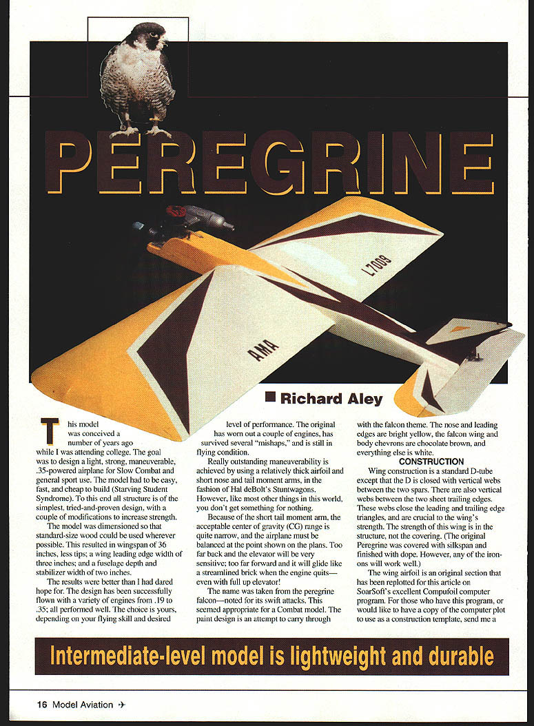
This model was conceived while I was attending college. The goal was to design a light, strong, maneuverable, .35-powered airplane for CL Slow Combat and general sport use. The model had to be easy, fast, and cheap to build (Starving Student Syndrome). The structure is of the simplest, tried-and-proven design, with a couple of modifications to increase strength.
The model was dimensioned so that standard-size wood could be used wherever possible. This resulted in a wingspan of 38 inches (less tips), a wing leading-edge width of 3 inches, and a fuselage depth and stabilizer width of 2 inches.
The design has been successfully flown with engines from .19 to .35 — all performed well. The original has worn out a couple of engines, has survived several mishaps, and is still in flying condition.
Outstanding maneuverability is achieved by using a relatively thick airfoil and short nose and tail moment arms, in the fashion of Hal deBolt's Stuntwagons. Because of the short tail moment arm, the acceptable center-of-gravity (CG) range is quite narrow; the airplane must be balanced at the point shown on the plans. Too far back and the elevator is very sensitive; too far forward and it will glide poorly when the engine quits, even with full up elevator.
The name was taken from the peregrine falcon — noted for its swift attacks. The paint scheme follows the falcon theme: nose and leading edges bright yellow, falcon wing and body chevrons chocolate brown, and everything else white.
Construction
Wing
The wing is a standard D-tube except that the D is closed with vertical webs between the two spars. There are also vertical webs between the two sheet trailing edges. These webs close the leading- and trailing-edge triangles and are crucial to the wing's strength. The wing's strength is in the structure, not the covering. The original Peregrine was covered with Silkspan and finished with dope; any of the modern film coverings will work well.
The wing airfoil is an original section that has been replotted with SoarSoft's Compufoil program. If you have Compufoil or would like a copy of the computer plot to use as a construction template, send a SASE and a copy of the Compufoil coordinates/airfoil plot will be sent.
Construction steps:
- Cover the plans with waxed paper.
- Pin a 1/4" square spar in place on the plans. Place scraps of 1/16" sheet between the spar and plans at each rib location to allow for the 1/16" sheet leading edge. Temporarily shim up the rib trailing edges with another 1/4" square spar so all rib trailing edges are parallel to the building board.
- Pin and glue all ribs in place, making sure they are perpendicular to the spar in both horizontal and vertical directions.
- Glue the 1/4" square leading edge and one of the 1/16" x 1/8" trailing-edge strips in place. Remove the 1/4" square shim and glue it on top of the ribs.
- When the glue is set enough to remove pins in the LE and top spar, pin and glue the top LE and center-section sheets in place. Carve or sand the top of the LE to match the ribs before gluing on the LE sheeting.
- Allow the whole assembly to dry thoroughly (preferably overnight) before removing from the plans.
- Turn the wing over and cut holes in the left-hand ribs for the leadout wires. Install the bellcrank mount, bellcrank, leadouts, pushrod, wingtips, leadout guides, and tip weight. Leave the pushrod extra long for now; it can be cut to size later when hooked up to the elevator.
- Pin and glue the other 1/16" LE center-section sheets in place. Cut a slot in the center-section sheet for the pushrod exit; make the slot as small as possible and located as close as possible to its final position. Once the stabilizer and elevator are installed you can enlarge the exit slot to provide pushrod clearance for full-range elevator travel.
- Now glue the other trailing-edge sheet in place with the wing pinned to the building board (trailing edge flat against the board). Use scrap 1/4" square shims under the bottom spar to ensure the wing is flat. Glue the webs between the front spars and the trailing-edge sheets. Allow glue to dry thoroughly to ensure a flat wing.
- Remove the wing from the building board and sand with 100-grit paper to remove rough edges and shape the leading edge and tips. Finish sanding with 220-grit and set aside.
Fuselage
The fuselage nose strength comes from plywood doublers and hardwood engine bearers that extend back to the wing leading edge. A common weak point on many models is the fuselage forward of the horizontal stabilizer; by maintaining a constant fuselage width all the way to the tail the side-load strength of the aft fuselage is greatly increased.
Construction steps:
- Glue 3/32" plywood doublers to the inside of the fuselage sides (a 10–15-minute epoxy works well). Be sure to make a left and a right side.
- Mark the locations of the five formers and epoxy the 3/8" x 1/2" engine mount to the inside of the fuselage sides.
- While epoxy cures, drill F2 with a #60 drill for the landing-gear bindings. Bind the 3/32" music-wire landing gear to it with soft copper wire and lock the binding with a coat of epoxy.
- Glue all five formers to one fuselage side at the marked locations, ensuring they are properly located and at 90° to the side. When dry, glue the other fuselage side to the formers.
- Position the engine and trim the fuselage sides and bottom as required to clear the needle valve, exhaust, and crankcase. When the engine is properly located, drill the engine mounts.
- Install the fuel tank and secure it with scrap balsa wedges glued in place. Drill a hole in F1 for the fuel line as required.
Caution: the fuselage is quite thin in the wing cutout area and is fragile at this stage. Handle with care.
Tail
- Sand tail surfaces smooth and round all edges except the lower edge of the vertical fin where it glues to the fuselage.
- Install elevator hinges and elevator control horn.
Assembly and finish
- Slide the fuselage over the wing and glue in place. Double-check that the wing is square with the fuselage.
- When the wing/fuselage joint is dry, glue the horizontal stabilizer in place, making sure it is square with the fuselage centerline and parallel to the wing. Glue the plywood tailskid in place.
- Open the pushrod exit hole in the wing center-section planking as required for clearance. Put the bellcrank and elevator in the neutral position and bend the pushrod to connect with the elevator control horn (use a Z-bend or a 90° bend with a wheel collar on the control horn). If desired, fit a threaded-rod adapter and a threaded clevis.
- The 1/16" music-wire pushrod is routed externally for simplicity. Because it is unsupported it will tend to buckle in compression (down elevator). To prevent this, install the pushrod guide: disconnect the pushrod from the elevator, slide the 1/16" soft-wire pushrod guide onto the pushrod, reconnect the pushrod, insert the guide through the fuselage sides at the proper location, and epoxy it to F4.
- Check the tank installation, then glue the top and bottom fuselage sheets in place. When dry, sand the fuselage to shape and glue the vertical fin in place, locating it as shown on the plans.
- Give the entire framework a final sanding with 220- or 320-grit sandpaper. Cover the wing, fin, and tail and apply the finish of your choice.
- When the finish is complete, install the engine and attach the wheels. Optionally add a canopy and pilot.
- Check the whole airplane carefully — pay particular attention to the engine and control system. Check balance; add weight to the nose or tail if required. Take a few photos for the record, then proceed to the flying field.
Good luck and happy landings.
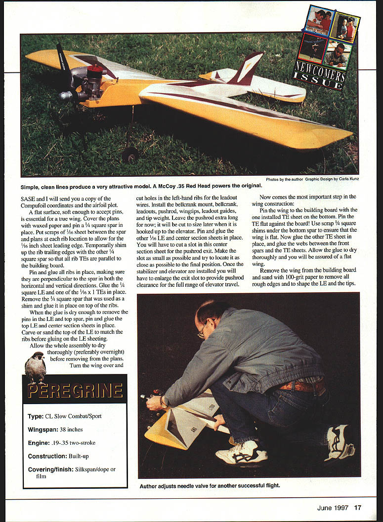
Specifications
- Type: CL Slow Combat / Sport
- Wingspan: 38 inches
- Engine: .19–.35 two-stroke
- Construction: Built-up
- Covering / finish: Silkspan/dope or film
Contacts
Richard P. Aley 3409 98th Pl. SE Everett, WA 98208
SoarSoft Software ATTN: Eric Sanders 3904 Traine Dr. Kettering, OH 45429
Transcribed from original scans by AI. Minor OCR errors may remain.

