
Perfect Hinges
David L. Peltz
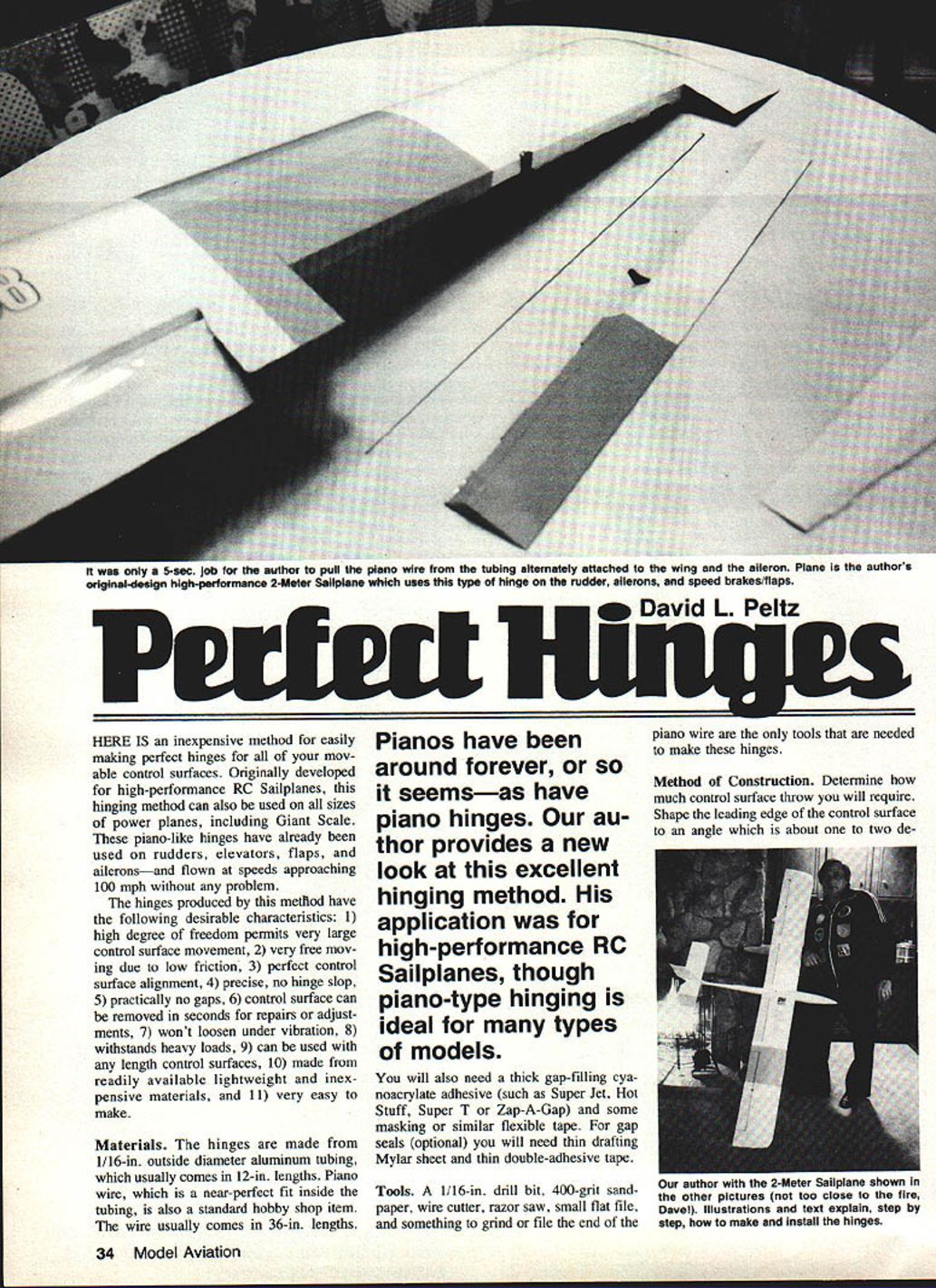
HERE IS an inexpensive method for easily making perfect hinges for all of your movable control surfaces. Originally developed for high-performance RC sailplanes, this hinging method can also be used on all sizes of power planes, including Giant Scale. These piano-like hinges have already been used on rudders, elevators, flaps, and ailerons—and have been flown at speeds approaching 100 mph without any problem.
Hinge characteristics
The hinges produced by this method have the following desirable characteristics:
- high degree of freedom permits very large control surface movement
- very free moving due to low friction
- perfect control surface alignment
- precise, no hinge slop
- practically no gaps
- control surface can be removed in seconds for repairs or adjustments
- won't loosen under vibration
- withstands heavy loads
- can be used with any length control surfaces
- made from readily available lightweight and inexpensive materials
- very easy to make
Materials
- 1/16-in. outside-diameter aluminum tubing (usually in 12-in. lengths)
- Piano wire (a near-perfect fit inside the tubing; usually available in 36-in. lengths)
- Thick gap-filling cyanoacrylate adhesive (e.g., Super Jet, Hot Stuff, Super T, Zap-A-Gap)
- Masking or similar flexible tape
- Optional gap seals: thin drafting Mylar sheet (not acetate) and thin double-adhesive tape
Pianos have been around forever, or so it seems—as have piano hinges. This application was for high-performance RC sailplanes, though piano-type hinging is ideal for many types of models.
Tools
- 1/16-in. drill bit
- 400-grit sandpaper
- Wire cutter
- Razor saw
- Small flat file
- Something to grind or file the end of the piano wire
Method of construction
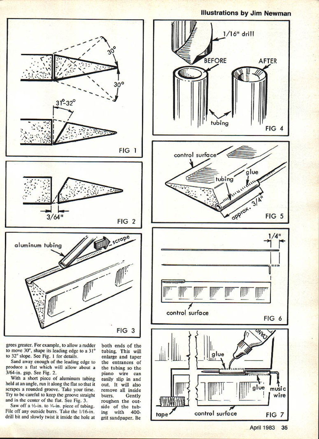
- Determine how much control surface throw you will require. Shape the leading edge of the control surface to an angle about one to two degrees greater than the maximum throw.
- Example: to allow a rudder to move 30°, shape its leading edge to a 31°–32° slope. (See Fig. 1.)
- Sand away enough of the leading edge to produce a flat that will allow about a 3/64-in. gap. (See Fig. 2.)
- With a short piece of aluminum tubing held at an angle, run it along the flat so that it scrapes a rounded groove. Take your time and keep the groove straight and centered on the flat. (See Fig. 3.)
- Saw off a 3/4-in. to 1-in. piece of tubing. File off any outside burrs. Use the 1/16-in. drill bit and slowly twist it inside the hole at both ends of the tubing. This will enlarge and taper the entrances of the tubing so the piano wire can easily slip in and out and will remove all inside burrs. Gently roughen the outside of the tubing with 400-grit sandpaper. Be careful—aluminum tubing bends very easily, so keep it as straight as possible. (See Fig. 4.)
- Carefully adhere the short piece of tubing to one end of the control surface. Be careful not to get any adhesive inside the tubing. (See Fig. 5.)
- Cut the piano wire to a length about 1/4 in. longer than the full length of the control surface. File or grind one end to a point. Make a 90° bend about 1/4 in. from the other end. (See Fig. 6.)
- Cut another piece of tubing about the same length as the first short piece. Treat both ends with the drill bit as before and roughen the outside with 400-grit sandpaper.
- Starting at the end of the control surface, insert the pointed end of the wire into the tubing already adhered to the control surface. Slip the loose short piece of tubing over the wire and slide it along until it just about touches the adhered piece of tubing.
- Carefully place the control surface in position on the wing (or other fixed surface) in the exact place you want it; the adhered tubing should just about touch the plane's surface. Use tape to hold the control surface in place. (See Fig. 7.)
- Attach the second piece of tubing to the fixed surface by placing a single drop of cyanoacrylate on the fixed surface at the center of the tubing. Make sure the control surface is still aligned. After the drop of adhesive has set, remove the wire and the control surface.
- Carefully run a bead of adhesive along the full length of both sides of the second piece of tubing to reinforce the joint where the tubing meets the fixed surface. Do not let adhesive get inside the tubing. Allow it to set. Trim excess tubing with a file or razor blade.
- Keep repeating this process along the entire length of the control surface, alternating adhering tubing to the fixed surface and to the control surface. Make sure the control surface remains aligned and does not wander out of position.
- Check for free movement. When let go, the control surface should easily fall from its own weight. If it doesn't, check for burrs or kinks in the tubing and wire. Also ensure that no two pieces of tubing are butted so tightly they scrape as the surface moves. Sand off any excess adhesive lumps.
Note: Be careful—aluminum tubing bends very easily; keep pieces as straight as possible. If additional stiffness or to prevent rotation of the tubing is desired, place a thin strip of Mylar over the tubing and secure it with double-sided tape.
To remove the control surface, simply pull out the piano wire and slide the control surface off. The hinge provides extremely low friction and precise alignment and has proven durable in high-speed flight.
Covering the surfaces
These steps occur after completion of the plane, when the surfaces are to be covered (e.g., with Super MonoKote).
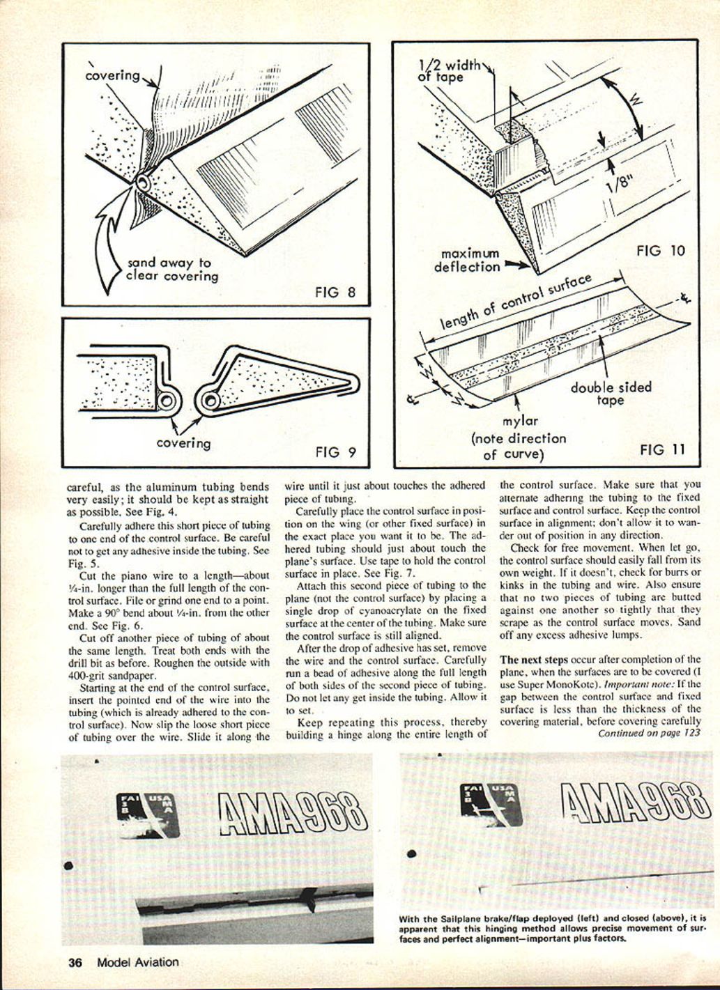
- Important: If the gap between the control surface and fixed surface is less than the thickness of the covering material, before covering carefully sand away just enough surface between each piece of tubing to allow a piece of covering material to slide through easily. (See Fig. 8.)
- When covering the plane and control surfaces, run the covering material around each piece of tubing so as to completely enclose it. This will hide its aluminum color and will also serve to strengthen the hinge considerably. (See Fig. 9.)
Optional gap seals (recommended for high-movement surfaces with large bevel angles)
- Cut a piece of drafting Mylar (do not use acetate) to the exact length of the control surface and to twice the desired width of the strip. The width is determined by moving the control surface to its maximum throw and adding one-half the width of the double-sticky tape plus another 1/8 in. (See Fig. 10.)
- Mark the center of the Mylar strip, and lay down the double-sticky tape along the center for the full length of the strip. If the Mylar came from a roll, it should have a natural curve; adhere the tape to the convex side so it will press against the control surface. (See Fig. 11.)
- Cut the strip in half along the full length. The tape will now be at the exact edge of what will be the front of the gap seal.
- Starting at one end, carefully lay down the Mylar strip so it is attached to the fixed surface (not the control surface). It will act as a gap seal.
You now have the most perfect control surface hinges you could hope for.
Transcribed from original scans by AI. Minor OCR errors may remain.

