
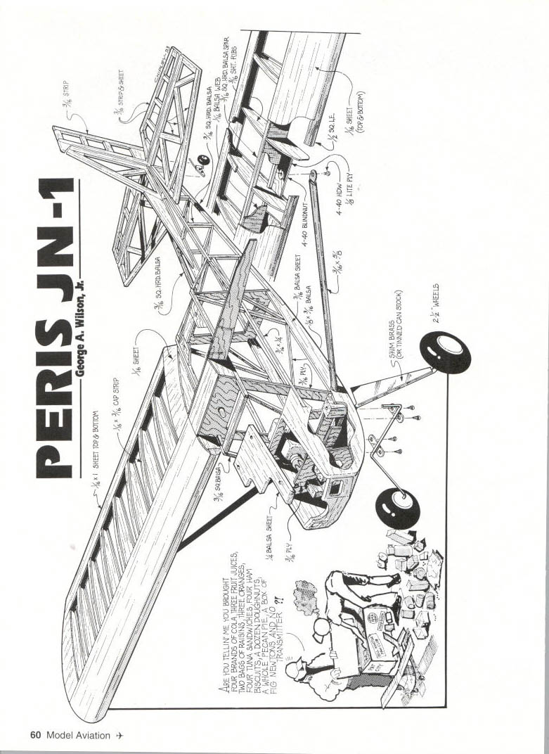
PERIS JN-1
George A. Wilson, Jr.
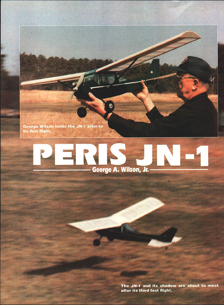
Most of us get "turned on" by one or more full-size airplanes—my latest turn-on is the Peris JN-1. My interest was stimulated by R. G. Schmitt's article in the November 1990 Model Builder on a small electric RC version of the JN-1.
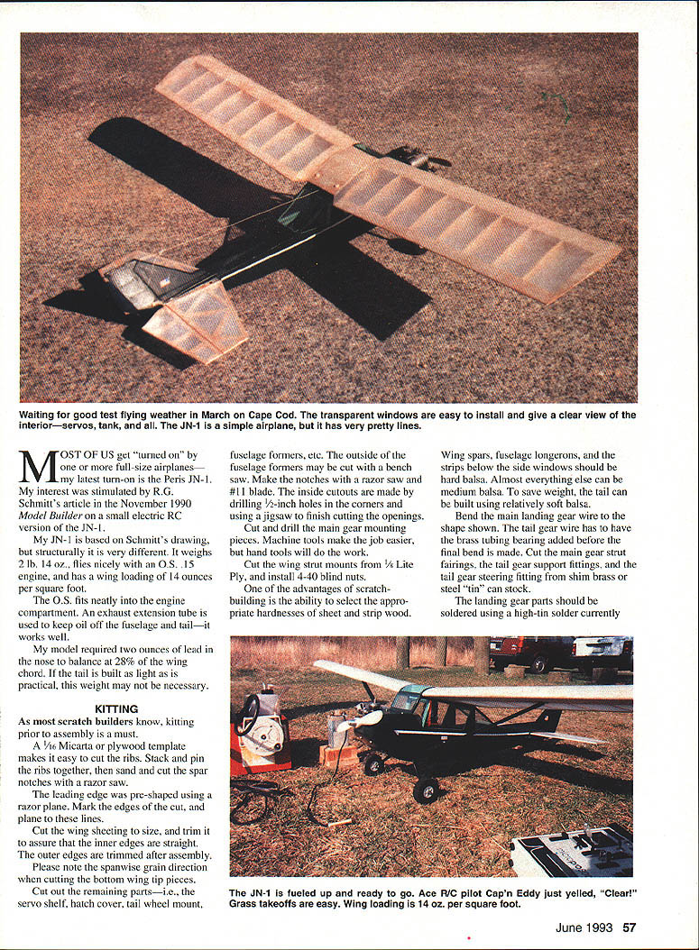
My JN-1 is based on Schmitt's drawing, but structurally it is very different. It weighs 2 lb. 14 oz., flies nicely with an O.S. .15 engine, and has a wing loading of 14 ounces per square foot.
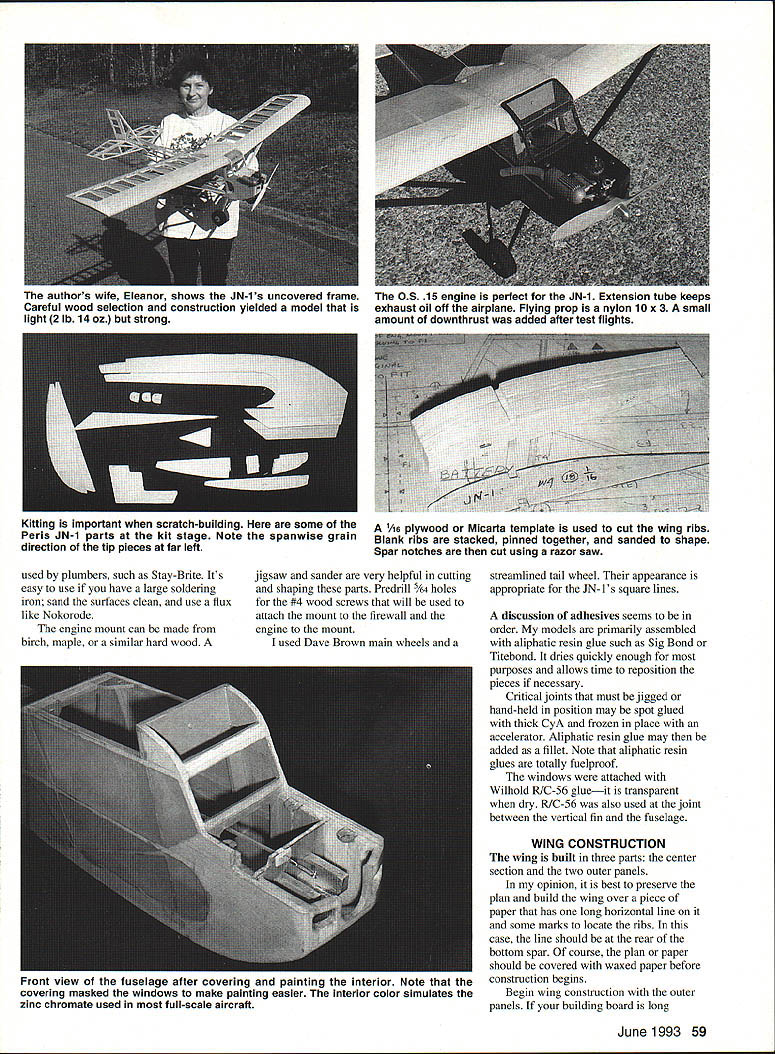
The O.S. fits neatly into the engine compartment. An exhaust extension tube is used to keep oil off the fuselage and tail—it works well.
My model required two ounces of lead in the nose to balance at 28% of the wing chord. If the tail is built as light as practical, this weight may not be necessary.
KITTING
As most scratch builders know, kitting prior to assembly is a must.
- Make a 1/16" Micarta or plywood template to cut the ribs. Stack and pin the ribs together, sand to shape, and cut the spar notches with a razor saw.
- Pre-shape the leading edge with a razor plane. Mark the edges of the cut and plane to those lines.
- Cut the wing sheeting to size and trim to assure the inner edges are straight. Trim the outer edges after assembly. Note the spanwise grain direction when cutting the bottom wing tip pieces.
- Cut out the remaining parts: servo shelf, hatch cover, tail wheel mount, fuselage formers, etc. The outside of the fuselage formers may be cut with a bench saw. Make notches with a razor saw and a #11 blade. Make inside cutouts by drilling 1/2" holes in the corners and finishing with a jigsaw.
- Cut and drill the main gear mounting pieces. Machine tools make the job easier, but hand tools will do the work.
- Cut the wing strut mounts from 1/8" lite ply and install 4-40 blind nuts.
One of the advantages of scratchbuilding is selecting appropriate wood hardnesses. Wing spars, fuselage longerons, and the strips below the side windows should be hard balsa. Almost everything else can be medium balsa. To save weight, build the tail from relatively soft balsa.
Bend the main landing-gear wire to the shape shown on the plan. Add the brass-tube bearing to the tail-gear wire before the final bend. Cut the main gear strut fairings, the tail-gear support fittings, and the tail-gear steering fitting from shim brass, steel, or tin-can stock.
Solder landing-gear parts using a high-tin solder such as Stay-Brite. Use a large soldering iron, sand the surfaces clean, and use flux (for example, Nokorode).
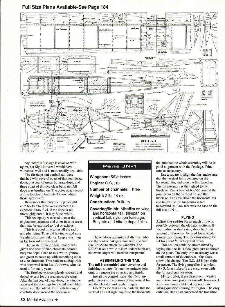
The engine mount can be made of birch, maple, or similar hardwood. A jigsaw and sander are helpful for cutting and shaping. Predrill 5/32" holes; #4 wood screws attach the mount to the firewall. I used Dave Brown main wheels. A streamlined tail wheel suits the JN-1's square lines.
Discussion of adhesives varies among builders. Most of my models are assembled primarily using aliphatic resin glues such as Sig Bond or Titebond. They dry quickly enough and allow repositioning. Critical joints must be jigged; a hand-held position may be spot-glued with thick CyA and frozen in place with accelerator. Aliphatic resin glue may be used to add fillets, but note it is not totally fuelproof.
Windows were attached with Wilhold R/C-56; it dries transparent. R/C-56 was also used on the joint between the vertical fin and the fuselage.
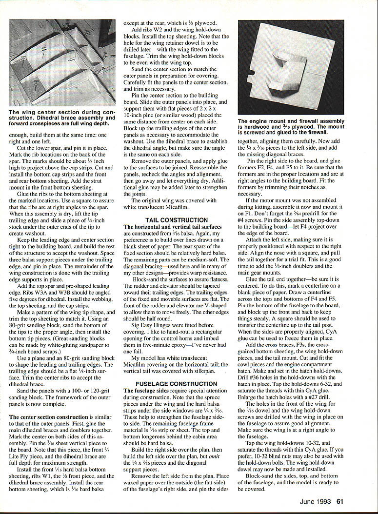
WING CONSTRUCTION
The wing is built in three parts: a center section and two outer panels. In my opinion, the best way to preserve the plan is to build the wing over the paper. The plan paper has a long horizontal line and some marks to locate the ribs; the line should be at the rear of the bottom spar. Cover the plan paper with waxed paper before construction begins.
Begin with the outer panels. If your building board is long enough, pin the front and rear spars to the plan and locate the ribs. If possible, build the outer panels at the same time—one right and one left.
- Use a 1/16" Micarta plywood template to cut the ribs. Stack-pin the blank ribs together and sand to shape. Cut spar notches with a razor saw.
- Pre-shape the leading edge with a razor plane; mark the edges and plane to the lines.
- Cut the wing sheeting to size and trim; assure the inner edges are straight. Trim outer edges after assembly.
- Cut the lower spar and pin it in place. Mark the rib locations on the back of the spar; the marks should be about 3/16" high to project above the cap strips. Cut and install the bottom cap strips and the front and rear bottom sheeting. Add the strut mount in the front bottom sheeting.
- Glue the ribs to the bottom sheeting at the marked locations. Use a square to ensure ribs are at right angles to the spar.
- When dry, lift the tip trailing edge and slide a piece of 1/4" stock under the outer ends of the tip to create washout. Keep the leading edge and center section tight to the building board, and build the rest of the structure to accept the washout.
- Space three balsa support pieces under the trailing edge and pin in place; complete remaining construction with these trailing-edge supports in place.
- Add the top spar and pre-shaped leading edge. Ribs W3A and W3B should be angled 5° for dihedral. Install the webbing, top sheeting, and cap strips.
- Make a pattern of the wing tip shape and trim the top sheeting to match. Using an 80-grit sanding block, sand the bottom of the tips to the proper angle, then install the bottom tip pieces (white-gluing sandpaper to 3/4" board scraps makes good sanding blocks).
- Use a plane and an 80-grit sanding block to shape the leading and trailing edges. The trailing edge should be a flat 1/8" surface. Trim the center ribs to accept the dihedral brace.
- Sand the panels with a 100- or 120-grit block. The outer-panel framework is now complete.
Center section construction is similar to the outer panels:
- Glue the main dihedral braces and doublers together. Mark the center on both sides of the assembly. Pin the 3/16" sheet vertical piece to the board. Note that this piece, the front 1/8" lite ply piece, and the dihedral brace are full depth for maximum strength.
- Install the front 1/16" hard balsa bottom sheeting, ribs W1, the 1/8" front piece, and the dihedral brace assembly. Install the rear bottom sheeting (1/16" hard balsa except at the rear, which is 1/8" plywood).
- Add ribs W2 and the wing hold-down blocks. Install the top sheeting. Note: the hole for the wing retainer dowel is drilled later with the wing fitted to the fuselage. Trim the wing hold-down blocks to be even with the wing top.
- Sand the center section to match the outer panels, carefully fit the panels to the center, and trim as necessary.
To join the panels:
- Pin the center section to the building board. Slide the outer panels into place and support them with flat pieces of 2 x 2 x 10" pine (or similar) placed the same distance from center on each side.
- Block up the trailing edges of the outer panels as necessary to accommodate the washout. Use the dihedral brace to establish the dihedral angle and ensure the angle is the same on each side.
- Remove the outer panels, apply glue to the surfaces to be joined, reassemble the panels, recheck angles and alignment, and let everything dry. Additional glue can be added later to strengthen the joints.
The original wing was covered with white translucent Micafilm.
TAIL CONSTRUCTION
The horizontal and vertical tail surfaces are constructed from 3/16" balsa. I prefer to build over lines drawn on a blank sheet of paper. The rear spars of the fixed section should be relatively hard balsa; the remaining parts can be medium-soft. Diagonal bracing provides warp resistance.
- Block-sand the surfaces to ensure flatness. The rudder and elevator should be tapered toward their trailing edges. The trailing edges of the fixed and movable surfaces are flat. The front of the rudder and elevator are V-shaped to allow free movement; other edges should be half-round.
- Fit Sig Easy Hinges before covering. I hand-route a rectangular opening for the control horns and embed them in five-minute epoxy—I’ve never had one fail.
My model has white translucent Micafilm covering on the horizontal tail and silkspan on the vertical tail. Finish choices are discussed in the Fuselage section.
FUSELAGE CONSTRUCTION
The fuselage sides require special attention during construction. The sparing pieces under the wing and the hard balsa strips under the side windows are 1/4" x 3/16". These help strengthen the fuselage side-to-side. The remaining fuselage frame material is 1/16" strip or sheet. The top and bottom longerons behind the cabin area should be hard balsa.
- Build the right side over the plan, then build the left side over the plan but omit the 1/4" x 3/16" pieces and the diagonal support pieces initially.
- Remove the left side from the plan. Place waxed paper over the outside (the flat side) of the right side and pin the sides together. Join the sides at the firewall and at F3 and F2. Add the top 1/16" pieces and the diagonal support pieces.
- The engine mount and firewall assembly are hardwood and 3/16" plywood. The mount is screwed and glued to the firewall—align them carefully. Now add the 1/4" x 3/16" pieces to the left side and add the missing diagonal braces.
- Pin the right side to the board and glue formers F2, F4, and F5 to it. Ensure the formers are in the proper locations and at right angles to the building board. Fit the formers by trimming their notches as necessary.
- If the motor mount was not assembled during kitting, assemble it now and mount it on F1. Predrill 5/64" holes for the #4 screws. Pin the side assembly top-down to the building board with F4 projecting over the top of the board.
- Attach the left side, making sure it is properly positioned relative to the right side. Align the nose with a square and pull the tail together for a trial fit. This is a good time to add the 1/4" doublers and the main gear mount.
- Glue the tail end together—be sure it is centered. Mark a centerline on a blank piece of paper and draw centerlines across the tops and bottoms of F4 and F5. Pin the bottom of the fuselage to the board and block up the front and back to keep things steady. Use a square to transfer the centerline up to the tail post.
- When the sides are properly aligned, CyA glue can be used to freeze them in place. Add cross braces, F3s, cross-grained bottom sheeting, the wing hold-down pieces, and the tail mount. Cut and fit the wing center section and the engine compartment floor. Make and set in the hatch hold-downs.
- Drill #36 holes in the hold-downs with the hatch in place. Tap the hold-downs 6-32 and saturate the threads with thin CyA glue. Enlarge the hatch holes with a #27 drill.
- Drill the holes in the front of the wing for the 3/16" dowel and the wing hold-down screws with the wing in place on the fuselage to assure good alignment. Make sure the wing is at a right angle to the fuselage.
- Tap the wing hold-downs 10-32 and saturate the threads with thin CyA glue. 10-32 blind nuts may also be used with the hold-down bolts. The wing hold-down bolt may now be made and installed.
- Block-sand the sides, top, and bottom of the fuselage; the model is now ready to be covered.
My model's fuselage is covered with nylon, but Sig's Koverall would also work and is more readily available. The fuselage and vertical tail were finished with several coats of thinned nitrate dope, one coat of green butyrate dope, and three coats of thinned clear butyrate—all brushed on. Remember that butyrate dope should cure for two to three weeks before exposure to raw fuel; if not thoroughly cured it may blush white.
Thinned epoxy was used to coat the engine compartment and other interior areas that may be exposed to fuel or exhaust.
Install the radio and plumbing now. To avoid adding nose weight for balance, keep everything as far forward as practical.
The inside of the original model was given one coat of zinc-chromate-colored butyrate dope. I mixed white, yellow, and green to approximate zinc chromate—an effect borrowed from Lou Andrews.
Cover the fuselage and dope it completely except for the area under the wing. After the last coat of clear dope, carefully cut out the window areas and the openings for the tail assemblies. This is easier than doping carefully around open areas.
Install the windows after the radio and control linkages have been checked. Use R/C-56 to attach the windows; it takes a while to cure under the plastic but eventually becomes transparent.
SPECIFICATIONS
- Wingspan: 56½ inches
- Engine: O.S. .15
- Number of channels: Three
- Weight: 2 lb. 14 oz.
- Construction: Built-up
- Covering/finish: Micafilm on wing and horizontal tail; silkspan on vertical tail; nylon on fuselage. Butyrate and nitrate dope finish.
ASSEMBLING THE TAIL
Assemble the tail after covering and finishing its parts. Where the surfaces join, omit or remove the covering and finish.
- Install the control horns, the 3/16" triangular pieces at the bottom of the vertical fin, and the elevator and rudder hinges.
- Check that all parts fit, that the vertical fin is at right angles to the horizontal fin, and that the whole assembly aligns properly with the fuselage. Trim and sand as necessary.
- Use a square to align the fins, center the vertical fin on the horizontal fin, and glue the fins together. Glue the fin assembly to the fuselage and run a bead of R/C-56 around the joint between the vertical fin and the fuselage.
- The area above the horizontal fin and below the top longerons is left uncovered, as was likely the case on the full-scale JN-1.
FLYING
Adjust the rudder for as much throw as possible between the elevator sections. If your radio has dual rates, use about half that amount for relaxed, trainer-type flying. Set the elevator for about 3/8" up and down.
The JN-1 flew great as shown on the plans. The only trim necessary was a small amount of downthrust—the plans show this change. The O.S. .15 is just right for power; the flying propeller is a nylon 10 x 3. Grass takeoffs are easy, even with the forward gear location.
My test pilot, Hans Sagemuehl, wanted me to take over just after takeoff; however, I feel more comfortable taking notes and asking questions during test flights. The only criticism Hans had concerned the transition from takeoff to the climbing turn—he said it wanted to float a little after lift-off, but a slight forward pressure on the elevator cured it. On landing, approach should be made with power on; taxiing after landing is not a problem because of the tail-skid steering. The model is very docile and easy to fly.
So build and enjoy. The Peris JN-1 is very cute. To date I have not been able to contact Messrs. Peris or Schmitt. Does the full-scale JN-1 fly without ailerons? Judging from the model, it could very well do that!
I would like to thank the late George O'Brien and my test pilot, Hans Sagemuehl, for their valuable help.
Transcribed from original scans by AI. Minor OCR errors may remain.

