
Perky
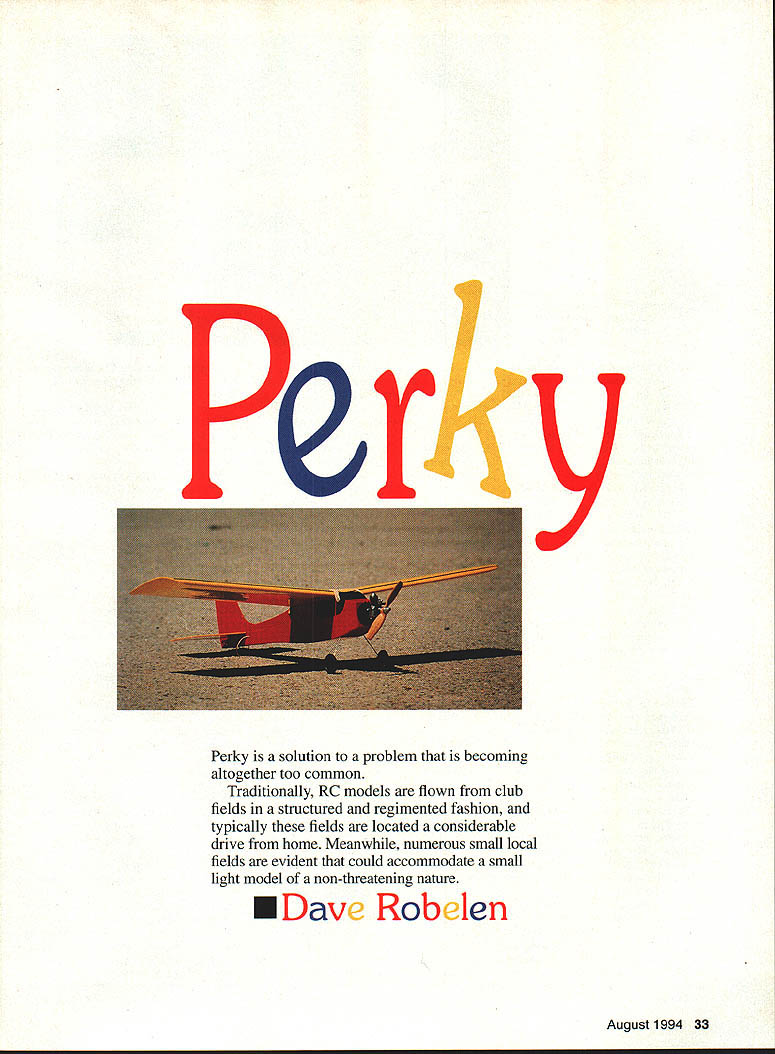
Perky is a solution to a problem that is becoming altogether too common.
Traditionally, RC models are flown from club fields in a structured and regimented fashion, and typically these fields are located a considerable drive from home. Meanwhile, numerous small local fields are evident that could accommodate a small light model of a non-threatening nature.
Perky is designed to make use of these smaller fields without totally compromising the quality of its basic flight characteristics. Perky must also handle breezy weather—which seems to be the only type I have.
I am not advocating flying models in "banned" areas, or failing in any way to conform to the AMA safety code; I am suggesting that by using a small, light, low-powered model, most of us could find some convenient local site to keep our skills honed between trips to the regular club field.
Although there have been a number of miniature RC projects in the past, none seemed to meet my requirements without major compromises. This led to the decision to create a fresh design, retaining the best qualities of past projects while expanding performance.
My personal preference is for a speedy, maneuverable craft; however, I wanted to be able to share Perky with my young kids as well, so it had to be capable of gentle, stable, hands-off flight typical of a trainer.
As I began the planning stages of Perky, a quick check of our hobby advertisements showed that Cox was still offering the cute little .010 engine, and Bill Cannon was producing the Super-Micro RC system. These products formed the basis for sizing this new project, as they combined to produce the smallest, lightest equipment package currently available.
The minimum all-up weight was going to be pretty much set by my choice of equipment and engine, and this appeared to be between 4-1/2 and 5 ounces, depending on final selection of construction and finishing materials. Based on previous experience I had decided on two-channel control as being completely adequate to provide the desired maneuverability while keeping the weight to a minimum.
The next decision area was the wing. My requirement of a minimum flying speed of 15 mph coupled with the projected weight tended to place the wing area at about 80 square inches, if I used a clean airfoil with normal lift capability.
The choice of a "best" airfoil was a major design challenge, as the top speed along with the maneuvering qualities would both be strongly affected by the final selection.
A literature search turned up some outstanding work done at Princeton University by Selig, Donovan, et al. dealing mainly with airfoils for RC sailplanes. Among the sections studied was the venerable Clark Y, which appeared to have superior performance on small low-speed wings. However, the data did not extend down to the minimum values calculated for Perky, so there was some uncertainty about the minimum speed and high-lift maneuvers. Regardless of this small problem, the Clark Y was chosen, based on the available data.
The actual layout and shape of Perky combines an effort to retain a connection with the "vintage" styles while using a minimum amount of material. The choice of a high-wing cabin style was strongly influenced by the desire for ease of handling, while experience has taught that rudder and elevator control would be quite adequate for any desired maneuvers.
The materials chosen for construction and finish include cyanoacrylate (CyA) adhesives and Super MonoKote covering, while the structure is good old balsa with a dab of plywood here and there. I am probably old-fashioned and narrow-minded, but I chose not to use any kind of modern composite materials seen so widely today—I used the KISS principle (Keep It Simple, Stupid) instead.
To maintain the pure airfoil shape and to provide extreme damage resistance, the wing is fully sheeted. Although there is a slight weight penalty, some of my flying site options justify this choice.
The size of the tail surfaces and the force arrangement follow standard practices established by many previous designs. The rather short nose was dictated by the weight of the engine relative to the rest of the model.
Construction of Perky went very quickly once all of the decisions had been reached and I finished procrastinating. The final weight is 4.75 ounces with all equipment, including a 75 mAh battery.
Once Perky was finished, the weather decided to play rough—wind, rain, and cold for a long week. Finally, a day came when the wind dropped to 10–15 mph with only moderate gusts.
For the initial flights I chose to use the stock 3.0 x 1.25 prop and Cox racing fuel. The top speed was immediately obvious: it was around 50 mph with the engine running full speed. The aerobatic capability was outstanding as well; it was performing consecutive loops, rolls, stall turns, snap rolls, spins, and much more by the third flight.
At this point, Perky was well established as a "performance" machine, but the gliding performance was less than desired, and slow flight required too much effort on the controls. Going back to the scientific literature, it seemed that a "laminar separation bubble" was forming on the top of Perky's wing at 25 mph and below.
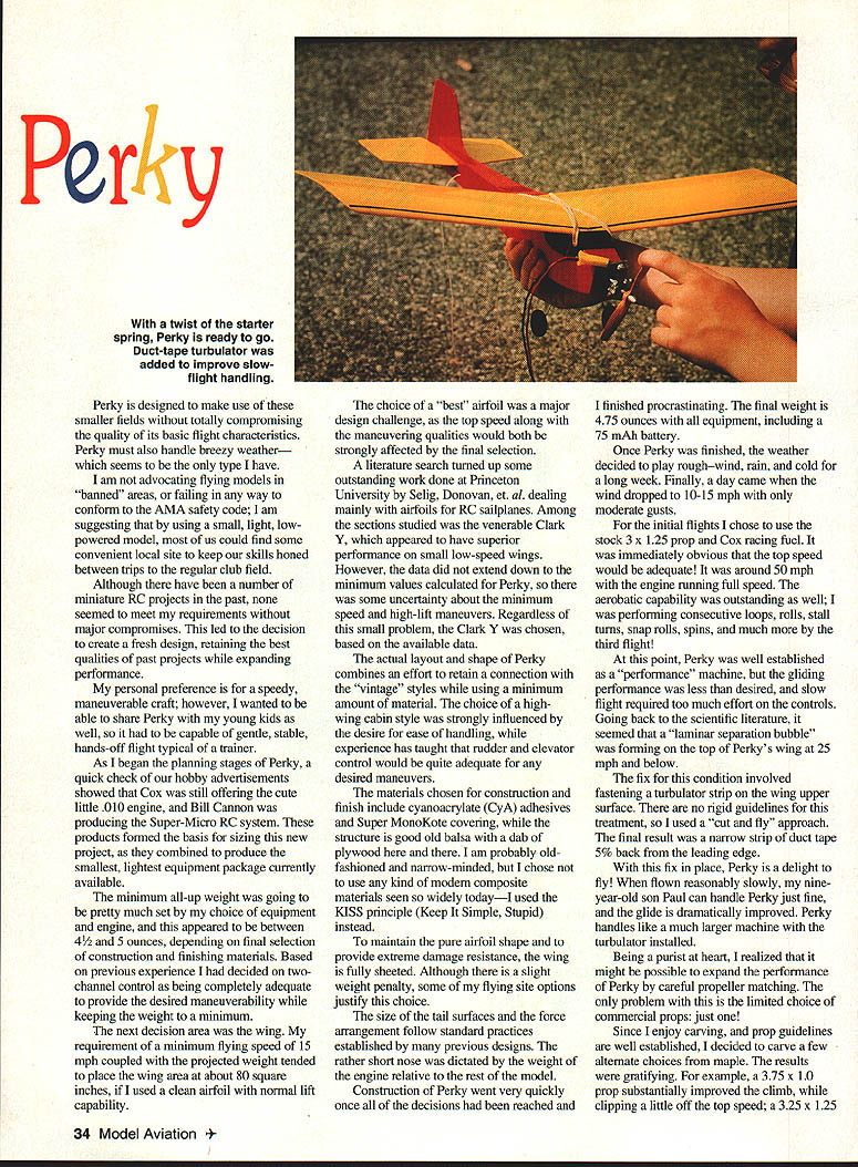
The fix for this condition involved fastening a turbulator strip on the wing upper surface. There are no rigid guidelines for this treatment, so I used a "cut and fly" approach. The final result was a narrow strip of duct tape set back from the leading edge about 5/8 inch. With this fix in place, Perky is a delight to fly. When flown reasonably slowly, my nine-year-old son Paul can handle Perky just fine, and the glide is dramatically improved. Perky handles like a much larger machine with the turbulator installed.
Being a purist at heart, I realized that it might be possible to expand the performance of Perky by careful propeller matching. The only problem with this is the limited choice of commercial props; just one!
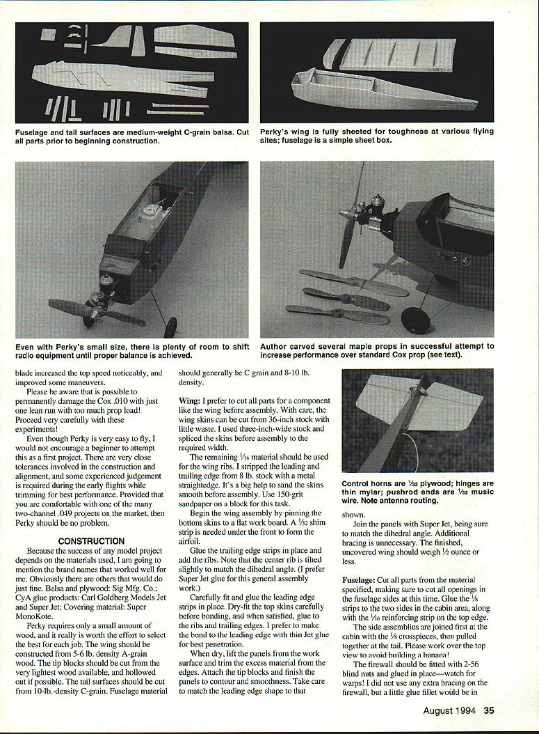
Since I enjoy carving and prop guidelines are well established, I decided to carve a few alternate choices from maple. The results were gratifying. For example, a 3.75 x 1.0 prop substantially improved the climb, while clipping a little off the top speed; a 3.25 x 1.25 blade increased the top speed noticeably and improved some maneuvers.
Please be aware that it is possible to permanently damage the Cox .010 with just one lean run with too much prop load! Proceed very carefully with these experiments!
Even though Perky is very easy to fly, I would not encourage a beginner to attempt this as a first project. There are very close tolerances involved in the construction and alignment, and some experienced judgment is required during the early flights while trimming for best performance. Provided that you are comfortable with one of the many two-channel .049 projects on the market, then Perky should be no problem.
Construction
Because the success of any model project depends on the materials used, I am going to mention the brand names that worked well for me. Obviously there are others that would do just fine.
- Balsa and plywood: Sig Mfg. Co.
- CyA glue products: Carl Goldberg Models Jet and Super Jet
- Covering material: Super MonoKote
Perky requires only a small amount of wood, and it really is worth the effort to select the best for each job. The wing should be constructed from 3–5 lb. density A-grain wood. The tip blocks should be cut from the very lightest wood available, and hollowed out if possible. The tail surfaces should be cut from 10-lb. density C-grain. Fuselage material should generally be C-grain and 8–10 lb. density.
Wing
I prefer to cut all parts for a component like the wing before assembly. With care, the wing skins can be cut from 36-inch stock with little waste. I used three-inch-wide stock and spliced the skins before assembly to the required width.
The remaining 1/16 material should be used for the wing ribs. I stripped the leading and trailing edge from 8-lb. stock with a metal straightedge. It's a big help to sand the skins smooth before assembly. Use 150-grit sandpaper on a block for this task.
Begin the wing assembly by pinning the bottom skins to a flat work board. A 1/32 shim strip is needed under the front to form the airfoil.
Glue the trailing edge strips in place and add the ribs. Note that the center rib is tilted slightly to match the dihedral angle. (I prefer Super Jet glue for this general assembly work.)
Carefully fit and glue the leading edge strips in place. Dry-fit the top skins carefully before bonding, and when satisfied, glue to the ribs and trailing edges. I prefer to make the bond to the leading edge with thin Jet glue for best penetration.
When dry, lift the panels from the work surface and trim the excess material from the edges. Attach the tip blocks and finish the tips to contour and smoothness. Take care to match the leading edge shape to that shown.
Join the panels with Super Jet, being sure to match the dihedral angle. Additional braces are unnecessary. The finished, uncovered wing should weigh 1/2 ounce or less.
Fuselage
Cut all parts from the material specified, making sure to cut all openings in the fuselage sides at this time. Glue the 1/8 strips to the two sides in the cabin area, along with the 1/8 reinforcing strip on the top edge.
The side assemblies are joined first at the tail with the 1/8 crosspieces, then pulled together at the nose. Work from the top view to avoid building a banana!
The firewall should be fitted with 2-56 blind nuts and glued in place—watch for warps! I did not use any extra bracing on the firewall, but a little glue fillet would be in order.
Cover the top and bottom with 1/32 sheet (grain running crosswise) after installing the plywood landing gear mount pieces. Sand smooth all over and set aside.
Tail surfaces
Cut all parts from C-grain 8 lb. balsa. Fashion the elevator joiner wire and attach to the elevators. Sand all parts smooth to prepare for covering.
Covering
Perky should be covered while all of the components are still separate. As mentioned, use Super MonoKote and work with care to avoid warping or damaging the delicate tail surfaces. Some of the colors weigh less than others; I used opaque red and transparent yellow.
Assembly
- Cut and install the plywood control horns on the tail surfaces. I used thin mylar drafting stock (about .006) for the hinges cut in 1/8-inch width and fastened with thin Jet. Check for smooth operation before proceeding, and make corrections if needed.
- Glue the horizontal tail in place, using the wing mounted on the cabin to check for alignment. Install the vertical tail now and add the bottom hinge. Mount the tailskid while back there. I used 1/64 dowels for the wing hold-downs, held in place with Super Jet.
- The landing gear is completed by fitting the pre-bent wire legs to the fuselage and adding .020 wire clamps. Attach everything together with thin Jet.
There are no really suitable wheels for this project, so I made a set. The result is a very light, tough, smooth-running wheel.
Starting with a thin plywood disk cut to size, I bonded a short piece of brass tubing in the center, then cut a tire from electrical insulation that is split and glued around the outer edge. Soak the wheels with thin Jet, and coat with a fuelproof paint for a really durable result.
The engine is fastened to the nose with 2-56 screws just long enough to reach into the blind nut; any longer could result in damage to the battery. Check the engine thrustline for any angles. There should be no down or side thrust.
Install the radio equipment loosely, and strap the wing on for a center of gravity (CG) check. It is vital to balance Perky at the designated location—move the equipment to achieve this condition and note the location of the components.
Mount the servos with servo mounting tape, and fit a piece of stiff sponge between them for vibration damping. Make up the pushrods from 3/32 square balsa and 1/32 music wire. I use a tiny dab of epoxy to trap the rods in the control horns.
Set the control throws as follows:
- Rudder: 3/16 inch left and right of center
- Elevator: 1/8 inch up and down
Mount the battery and receiver using soft sponge rubber or foam. Make sure they cannot touch anything solid, and route the antenna out of the tail. Let the excess antenna trail behind—don't be tempted to cut it off or coil up the extra; the result would be a loss of control!
Preflight Perky by performing a range check per the receiver instructions. Do the final alignment check on a flat surface (the kitchen counter). Mount the Cox 3.0 x 1.25 prop backward, and finish whatever engine check runs you need to ensure reliable operation.
If possible, choose a soft, grassy site for the first flights. With the engine running slightly rich, toss Perky into the wind with about 1/4 tank of fuel aboard. Spend the first few flights checking out the feel of the model and learning the glide performance. Just like the space shuttle, you only get one try!
From this point on it's up to you to make the fine adjustments that are normal to get the most of your model. Since anything can be improved, I would be glad to hear your comments and feedback regarding Perky.
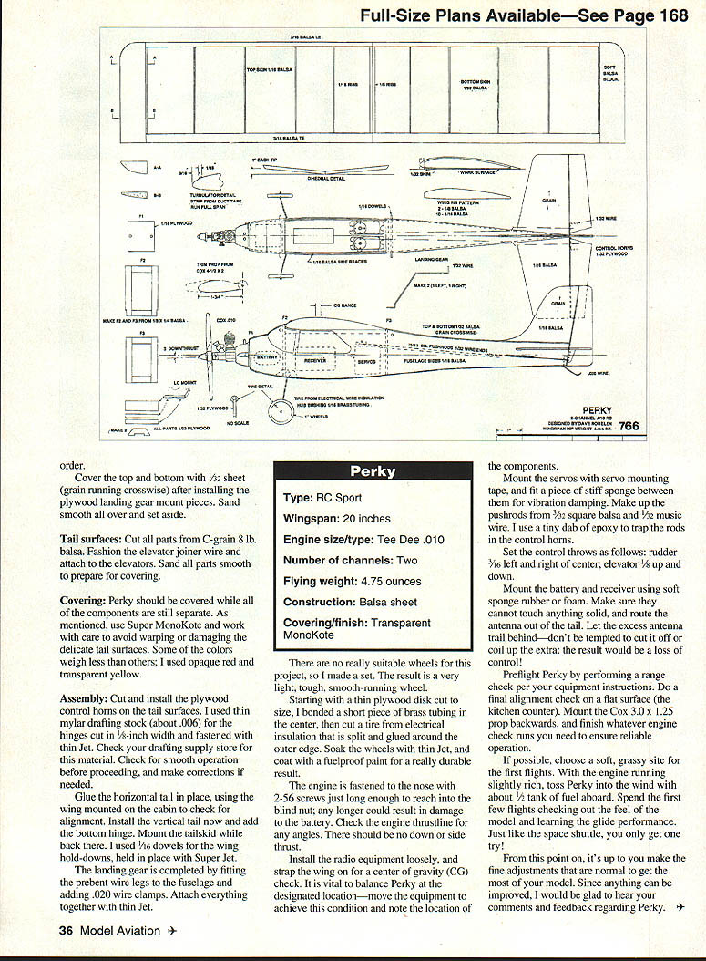
Specifications
- Type: RC Sport
- Wingspan: 20 inches
- Engine size/type: Cox .010
- Number of channels: Two
- Flying weight: 4.75 ounces
- Construction: Balsa sheet
- Covering/finish: Super MonoKote (transparent/opaque options)
Transcribed from original scans by AI. Minor OCR errors may remain.

