
Pete
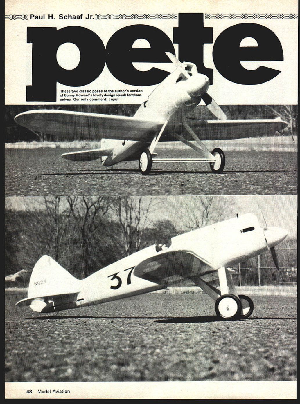
Paul H. Schaaf Jr.
AIR racing has been with us nearly as long as powered flight. In 1909, Glenn Curtiss, in the first official air race in France, the Bennett Cup International, flew at a speed of 47.65 mph. Since an American won this first race, races began to be held in the United States the following year and thereafter. In the early years practically every race resulted in some kind of record that only lasted until the next race.
It was only after World War I that air racing became more serious with the creation of valuable trophies and honors for the winners. Some early races were the Schneider Trophy, the Pulitzer Trophy and, later in 1929, the famous Cleveland National Air Races and Thompson Trophy Race.
One of the more famous racing planes of the 1930 era was Ben Howard's "Pete," which I have modeled in U-Control. Pete had a wingspan of 20.1 feet and a length of 17.65 feet. There was only a minimum of room for the pilot. Extra fuselage panels beside the cockpit had to be opened before the pilot could enter the plane.
- Key prototype dimensions and notes:
- Wingspan: 20.1 ft
- Length: 17.65 ft
- Very tight cockpit access; side panels open for entry
- Scale modeled as a .20/.30 powered control-liner with a 3-line system and throttle control
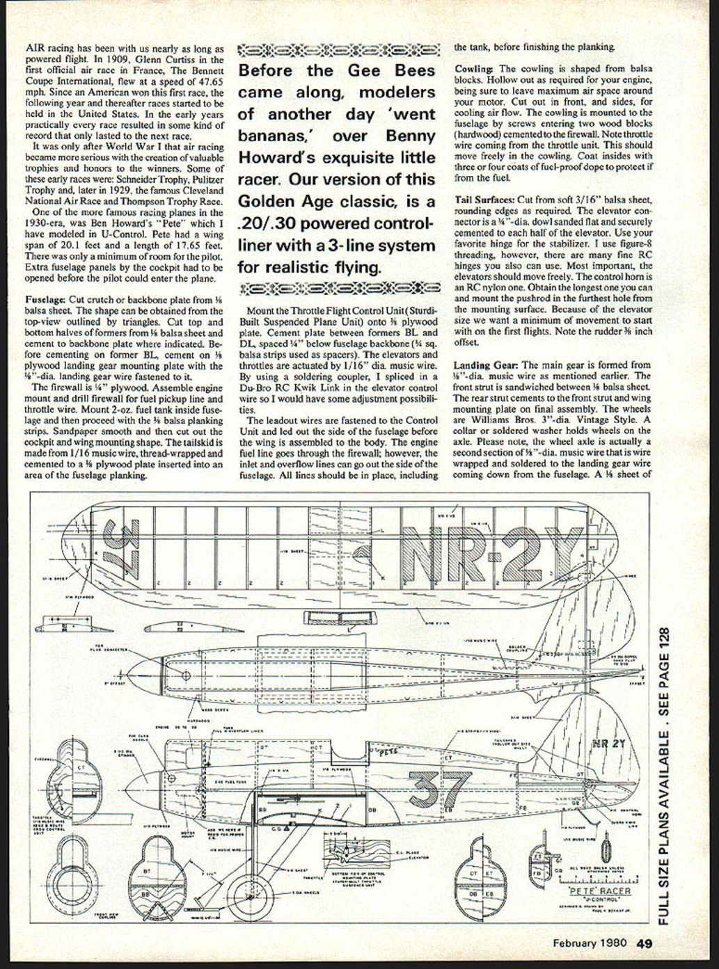
Fuselage
Cut the crutch (backbone) plate from 1/8" balsa sheet. The shape can be obtained from the top view outlined by triangles. Cut top and bottom halves of the formers from 1/8" balsa sheet and cement them on the backbone plate where indicated. Before cementing on former BL, cement on a 1/8" plywood landing gear mounting plate with 1/4"‑dia. landing gear wire fastened to it.
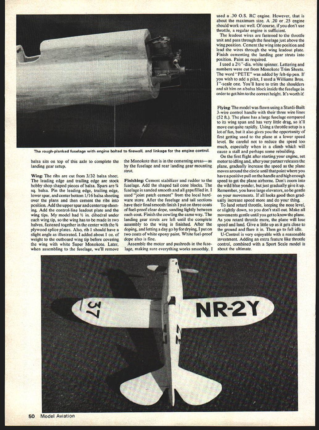
Assemble the engine mount and drill the firewall for the fuel pickup line and throttle wire. Mount a 2-oz. fuel tank inside the fuselage and then proceed with 1/8" balsa planking strips. Sand smooth, then cut out the cockpit and wing-mounting shape. The tailskid is made from 1/16" music wire, thread-wrapped and cemented to a 1/8" plywood plate inserted into an area of the fuselage planking.
Before the Gee Bees came along, modelers went "bananas" over Ben Howard's exquisite little racer. Our version of this Golden Age classic is a .20/.30 powered control-liner with a 3-line system for realistic flying.
Mount the throttle flight control unit (Sturdi-Built suspended plane unit) onto a 1/8" plywood plate. Cement the plate between formers BL and DL, spaced 1/4" below the fuselage backbone (3/4" sq. balsa strips used as spacers). The elevators and throttle are actuated by 1/16" dia. music wire. By using a soldering coupler, I spliced in a Du-Bro RC Kwik Link in the elevator control wire so I would have some adjustment possibilities.
The leadout wires are fastened to the control unit and led out the side of the fuselage before the wing is assembled to the body. The engine fuel line goes through the firewall; however, the inlet and overflow lines can exit out the side of the fuselage. All lines should be in place, including the tank, before finishing the planking.
Cowling
The cowling is shaped from balsa blocks. Hollow out as required for your engine, being sure to leave maximum air space around your motor. Cut openings in the front and sides for cooling airflow. Mount the cowling to the fuselage by screws entering two hardwood blocks cemented to the firewall. Ensure the throttle wire coming from the throttle unit moves freely within the cowling. Coat the inside with three or four coats of fuel-proof dope to protect it from fuel.
Tail Surfaces
Cut tail surfaces from soft 3/16" balsa sheet, rounding edges as required. The elevator connector is a 1/4"‑dia. dowel sanded flat and securely cemented to each half of the elevator. Use your favorite hinge for the stabilizer; I use figure‑8 threading, though fine RC hinges are also suitable. Most important, the elevators should move freely.
The control horn is an RC nylon unit—obtain the longest one you can and mount the pushrod in the hole farthest from the mounting surface. Because of the elevator size, use a minimum of movement for the first flights. Note the rudder is offset by 3/8".
Landing Gear
The main gear is formed from 5/32"‑dia. music wire. The front strut is sandwiched between 1/8" balsa sheet. The rear strut cements to the front strut and the wing-mounting plate on final assembly. The wheels are Williams Bros. 3"‑dia. vintage style. A collar or soldered washer holds the wheels on the axle.
Note: the wheel axle is actually a second section of 1/16"‑dia. music wire that is wire-wrapped and soldered to the landing gear wire coming down from the fuselage. A 1/8" sheet of balsa sits atop the axle to complete the landing gear setup.
Wing
- Ribs: cut from 3/32" balsa sheet.
- Use leading edge and trailing edge stock from the hobby shop and shaped pieces of balsa.
- Spars: 3/16" sq. balsa.
Pin the leading edge, trailing edge and lower spar in position; apply bottom 1/16" balsa sheeting over the plans and cement ribs in position. Add the upper spar and center top sheeting. Add the control-line leadout plate and wing tips. Model dihedral under the wing tip. The wing is made in two halves fastened together with center plywood splice plates. Each rib should have the slight angle as illustrated. Add about 1/2 oz. weight to the outboard wing tip.
Later, when assembling to the fuselage, remove any Monokote from the cementing areas (by the fuselage and rear landing gear mounting strut).
Finishing and Assembly
Cement the stabilizer and rudder to the fuselage. Add the shaped tail cone blocks. Sand the fuselage smooth and fill all gaps (I used joint patch cement from the hardware store). After the fuselage and tail sections have their final smooth finish, apply three coats of fuel-proof clear dope, sanding lightly between each coat. Finish the cowling the same way. Leave the landing gear struts off until the complete assembly to the wing is finished.
After doping and allowing a day to dry, apply two coats of white epoxy paint (white fuel-proof dope is also fine).
Assemble the motor and pushrods in the fuselage, making sure everything works smoothly. I used a .30 O.S. RC engine; that is about the maximum size. A .20 or .25 engine should work well. If you don't use throttle, a regular engine is sufficient.
The leadout wires are fastened to the throttle unit and pass through the fuselage just above the wing position. Cement the wing into position and lead the wires through the wing leadout plate. Finish cementing the landing gear struts into position and paint as required.
I used a 2 1/2"‑dia. white spinner. Lettering and numbers were cut from Monokote trim sheets. The word "PETE" was added by felt-tip pen. If you wish to add a pilot, I used a Williams Bros. 1" scale one. You'll have to trim the shoulders and seat him on a balsa block inside the fuselage in order to get him to the correct height. It's worth it!
Flying
The model was flown using a Sturdi-Built 3-wire control handle with their three-wire lines (52 ft.). The plane has a large fuselage compared to its wingspan and has very little drag, so it will move out quite rapidly. Using a throttle setup is a lot of fun, and it also gives you the opportunity to first get used to the plane at a lower speed level. Be careful not to reduce the speed too much, especially when in a climb, as that will cause a stall and perhaps some rebuilding.
First-flight procedure:
- Set the motor to idle.
- Have your partner release the plane.
- Gradually increase speed as the plane moves around the circle until you have a positive pull on the handle and enough speed to get the plane airborne.
- Do not zoom off; just gradually give it up. Remember you have large elevators—be gentle with movements.
- If all looks good, gradually increase speed and fly as desired.
To land:
- Retard the throttle while keeping the nose level or slightly down to avoid stalling.
- Make gentle control movements until you know the plane well.
- As speed bleeds off, the plane will settle toward the ground; give a little up as it approaches and flare it in, then go to full idle.
U-Control is very enjoyable for a reasonable investment. Adding an extra feature like throttle control, combined with a sport-scale model, is about the ultimate.
Transcribed from original scans by AI. Minor OCR errors may remain.

