
Pfalz E.V
BY BOB WALLACE
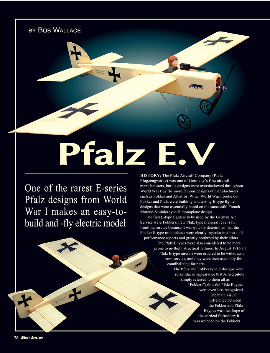
One of the rarest E-series Pfalz designs from World War I makes an easy-to-build and -fly electric model.
HISTORY
The Pfalz Aircraft Company (Pfalz Flugzeugwerke) was one of Germany’s first aircraft manufacturers, but its designs were overshadowed throughout World War I by the more famous designs of manufacturers such as Fokker and Albatros. When World War I broke out, Fokker and Pfalz were building and testing E-type fighter designs that were essentially based on the successful French Morane-Saulnier Type H monoplane design.
The first E-type fighters to be used by the German Air Service were Fokkers. Few Pfalz E-type aircraft ever saw frontline service because it was quickly determined that the Fokker E-type monoplanes were clearly superior in almost all performance aspects and greatly preferred by their pilots. The Pfalz E types were also considered to be more prone to in-flight structural failures. In August 1916 all Pfalz E-type aircraft were ordered to be withdrawn from service, and they were then used only for cannibalizing parts.
The Pfalz and Fokker type E designs were so similar in appearance that Allied pilots simply referred to them all as “Fokkers”; thus the Pfalz E types were even less recognized. The main visual difference between the Fokker and Pfalz E types was the shape of the vertical fin/rudder: rounded on the Fokker and squared off on the Pfalz. The most distinguishing visual feature associated with the E.V was its use of a Mercedes liquid-cooled, in-line engine rather than the commonly used Oberursel rotary engine. The E.V did offer improved flight performance, but it was still inferior to the more favored Fokker E designs. A total of 20 E.Vs were built, but only three were ever used in frontline air units.
Model Selection
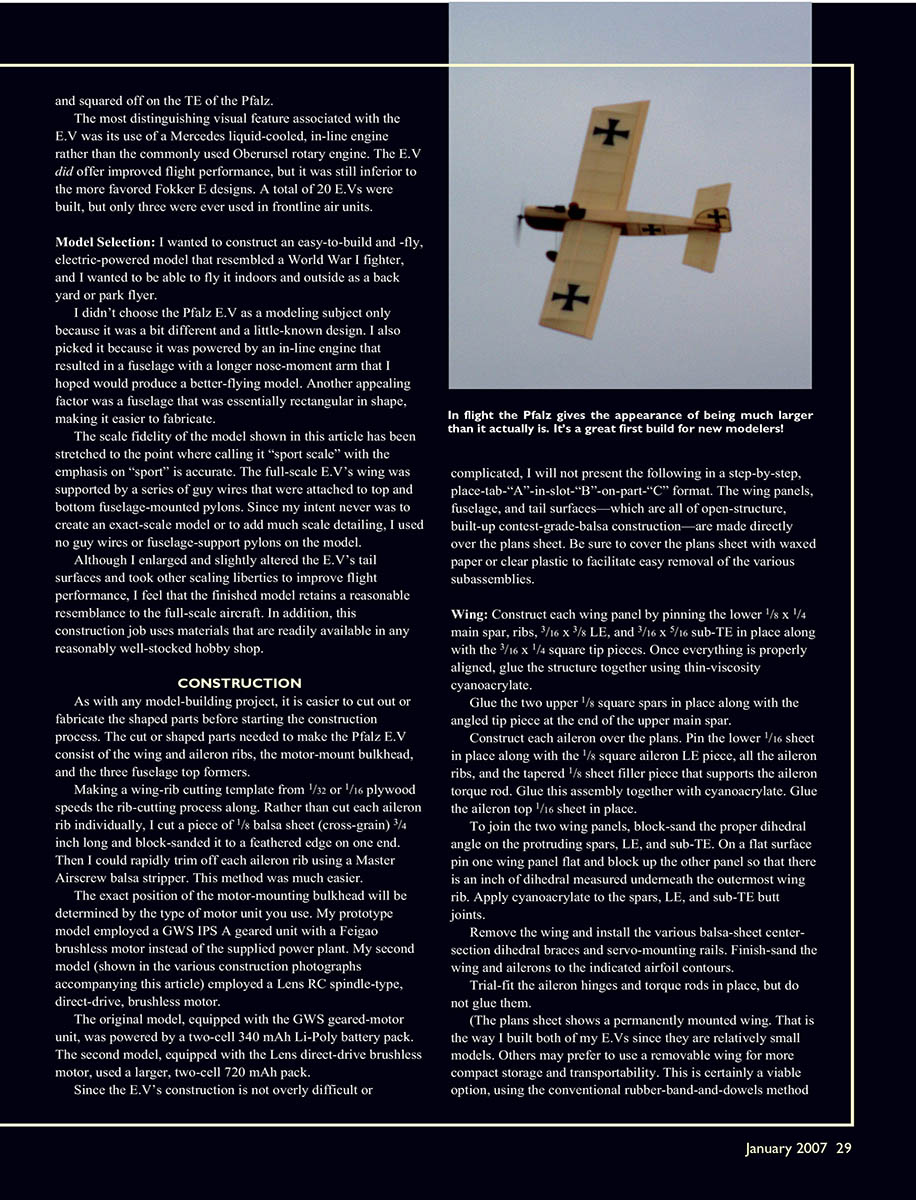
I wanted to construct an easy-to-build and -fly, electric-powered model that resembled a World War I fighter and that I could fly both indoors and outdoors as a backyard or park flyer.
I didn't choose the Pfalz E.V as a modeling subject only because it was a bit different and a little-known design. I also picked it because it was powered by an in-line engine that resulted in a fuselage with a longer nose–moment arm that I hoped would produce a better-flying model. Another appealing factor was a fuselage that was essentially rectangular in shape, making it easier to fabricate.
The scale fidelity of the model shown in this article has been stretched to the point where calling it "sport scale" with the emphasis on "sport" is accurate. The full-scale E.V.'s wing was supported by a series of guy wires attached to top- and bottom-fuselage-mounted pylons. Since my intent was never to create an exact-scale model or to add much scale detailing, I used no guy wires or fuselage-support pylons on the model.
Although I enlarged and slightly altered the E.V.'s tail surfaces and took other scaling liberties to improve flight performance, the finished model retains a reasonable resemblance to the full-scale aircraft. This construction job uses materials that are readily available in any reasonably well-stocked hobby shop.
CONSTRUCTION
As with any model-building project, it is easier to cut out or fabricate the shaped parts before starting the construction process. The cut or shaped parts needed to make the Pfalz E.V consist of the wing and aileron ribs, the motor-mount bulkhead, and the three fuselage top formers. Making a wing-rib cutting template from 1/32" or 1/16" plywood speeds the rib-cutting process. Rather than cut each aileron rib individually, I cut a piece of 1/8" balsa sheet (cross-grain) 3/4" long and block-sanded it to a feathered edge on one end. Then I could rapidly trim off each aileron rib using a Master Airscrew balsa stripper. This method was much easier.
The exact position of the motor-mounting bulkhead will be determined by the type of motor unit you use. My prototype model employed a GWS IPS-A geared unit with a Feigao brushless motor instead of the supplied power plant. My second model (shown in the construction photographs accompanying this article) employed a Lenz RC spindle-type, direct-drive brushless motor.
The original model, equipped with the GWS geared-motor unit, was powered by a two-cell 340 mAh Li-Poly battery pack. The second model, equipped with the Lenz direct-drive brushless motor, used a larger two-cell 720 mAh pack.
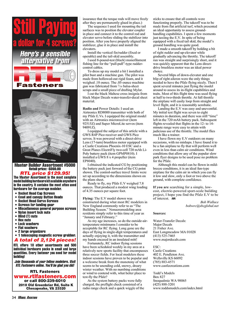
Since the E.V.'s construction is not overly difficult or complicated, the following is not presented in a step-by-step, place-tab-"A"-in-slot-"B"-on-part-"C" format. The wing panels, fuselage, and tail surfaces — all open-structure, built-up contest-grade balsa construction — are made directly over the plans sheet. Be sure to cover the plans sheet with waxed paper or clear plastic to facilitate easy removal of the various subassemblies.
Wing
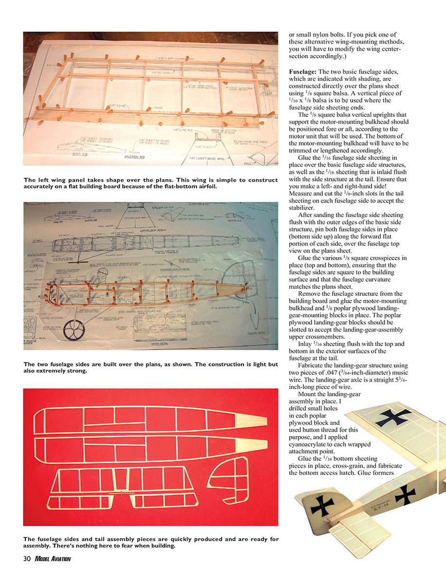
- Construct each wing panel by pinning the lower 1/8" x 1/4" main spar, ribs, 3/16" x 3/16" leading edge (LE), and 1/16" x 5/16" sub–trailing edge (sub-TE) in place, along with the 3/16" x 1/4" square tip pieces. Once everything is properly aligned, glue the structure together using thin-viscosity cyanoacrylate.
- Glue the two upper 1/8" square spars in place along with the angled tip piece at the end of the upper main spar.
- Construct each aileron over the plans. Pin the lower 1/16" sheet in place along with the 1/8" square aileron LE piece, all the aileron ribs, and the tapered 1/8" sheet filler piece that supports the aileron torque rod. Glue this assembly with cyanoacrylate. Glue the aileron top 1/16" sheet in place.
- To join the two wing panels, block-sand the proper dihedral angle on the protruding spars, LE, and sub-TE. On a flat surface pin one wing panel flat and block up the other so that there is 1" of dihedral measured underneath the outermost wing rib. Apply cyanoacrylate to the spars, LE, and sub-TE butt joints.
- Remove the wing and install the various balsa-sheet center-section dihedral braces and servo-mounting rails. Finish-sand the wing and ailerons to the indicated airfoil contours.
- Trial-fit the aileron hinges and torque rods in place, but do not glue them.
(Note: The plans sheet shows a permanently mounted wing. That is the way I built both of my E.Vs since they are relatively small models. Others may prefer a removable wing for more compact storage and transportability. This is a viable option using the conventional rubber-band-and-dowels method or small nylon bolts. If you pick one of these alternative wing-mounting methods, you will have to modify the wing center-section accordingly.)
Fuselage
- The two basic fuselage sides, indicated with shading on the plans, are constructed directly over the plans sheet using 1/8" square balsa. A vertical piece of 1/16" x 1/8" balsa is to be used where the fuselage side sheeting ends.
- The 1/8" square balsa vertical uprights that support the motor-mounting bulkhead should be positioned fore or aft according to the motor unit that will be used. The bottom of the motor-mounting bulkhead will have to be trimmed or lengthened accordingly.
- Glue the 1/16" fuselage side sheeting in place over the basic fuselage side structures, as well as the 1/16" sheeting that is inlaid flush with the side structure at the tail. Ensure that you make a left- and right-hand side. Measure and cut the 1/8" slots in the tail sheeting on each fuselage side to accept the stabilizer.
- After sanding the fuselage side sheeting flush with the outer edges of the basic side structure, pin both fuselage sides in place (bottom side up) along the forward flat portion of each side over the fuselage top view on the plans sheet.
- Glue the various 1/8" square crosspieces in place (top and bottom), ensuring that the fuselage sides are square to the building surface and that the fuselage curvature matches the plans sheet.
- Remove the fuselage structure from the building board and glue the motor-mounting bulkhead and 1/8" poplar plywood landing-gear-mounting blocks in place. The poplar plywood landing-gear blocks should be slotted to accept the landing-gear-assembly upper crossmembers.
- Inlay 1/16" sheeting flush with the top and bottom exterior surfaces of the fuselage at the tail.
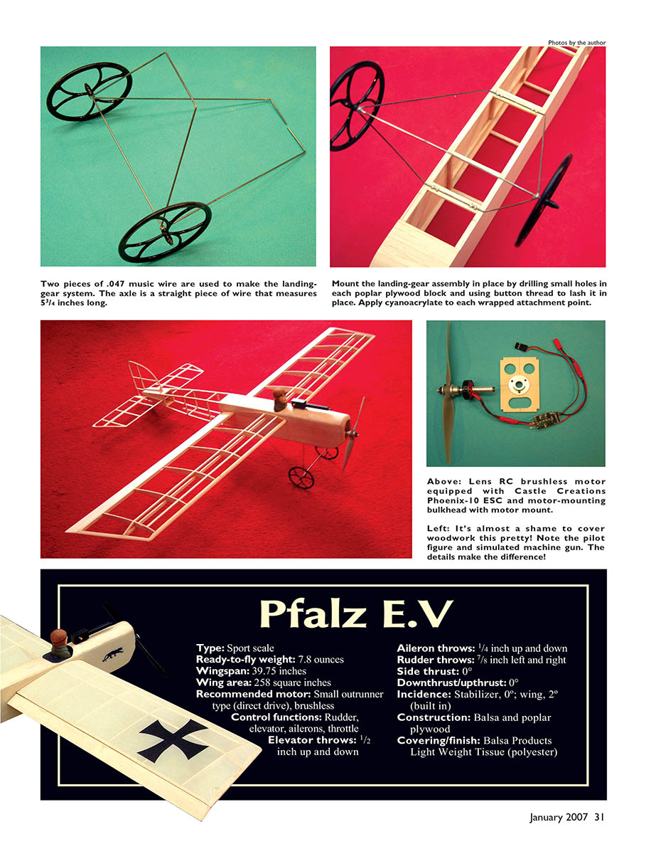
- Fabricate the landing-gear structure using two pieces of .047" (7/64" diameter) music wire. The landing-gear axle is a straight 5-3/4" long piece of wire.
- Mount the landing-gear assembly in place. I drilled small holes in each poplar plywood block and used button thread for this purpose, and I applied cyanoacrylate to each wrapped attachment point.
- Glue the 1/16" bottom sheeting pieces in place, cross-grain, and fabricate the bottom access hatch. Glue formers F1, F2, and F3 in place along with the top sheeting from F3 aft. Install the forward top sheeting over the formers. Glue the 1/4" sheet nose block in place.
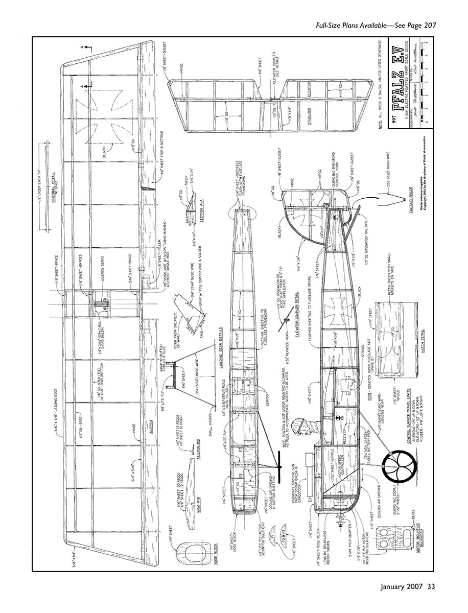
- Fabricate the 1/8" square basswood tail skid and .032" (7/64" diameter) music-wire brace, and trial-fit this assembly. Do not glue it in place at this time; it is easier to permanently install after the fuselage has been covered.
The next step will depend on which method of attaching the wing is to be employed. If the wing is to be permanently installed, as shown on the plans sheet, mark and cut out the sheeting on each side of the fuselage to accept the wing. (The plywood template made to cut out the wing ribs comes in handy for this, but be sure to allow for the LE and sub-TE portions.)
If you prefer a removable wing, carefully cut and remove the upper portion of the fuselage aft from former F3 and directly above the wing, down to the 1/8" square lateral fuselage pieces that provide the proper wing incidence.
After mounting the wing to the fuselage — using either the rubber-band-and-dowel or nylon-bolt method — trim the removed portion of the fuselage to fit in its original position (flush with the fuselage) and glue it in place on top of the wing center-section.
Sand the nose block to the indicated contour, and feather the fuselage sheeting flush with the 1/8" fuselage longerons. Cut the engine access and cooling opening in the nose block. Fine-sand the entire fuselage assembly.
Tail Surfaces
Construct all the tail surfaces, primarily from 1/8" square balsa, directly over the plans sheet.
Use two pieces of 1/16" x 1/8" balsa, laminated to facilitate bending, on the radiused portions of the vertical fin/rudder. After construction, lightly block-sand all the tail surfaces, radius all the perimeter edges, and trial-fit the hinges.
Fashion the elevator coupler from a piece of 1/16" dowel, such as the wood portion of an ordinary cotton-tipped applicator. Cut the horn portion from a small piece of 1/32" plywood.
My original model employed a fixed rudder and the second model used an operable rudder. Both fly fine, but the version equipped with a controllable rudder is more aerobatic and can be taxied.
Covering
Both of my E.V.s were covered with Balsa Products' Light Weight Tissue made from polyester fiber. I selected the Antique White color because it more closely resembles the early World War I fabric finishes that were used.
This heat-shrinkable tissue results in a far more realistic finish than the glossy film-type coverings. And although it is slightly porous, it is water resistant.
Since this material does not have an adhesive backing, apply a coat of heat-activated adhesive, such as Bassaloc, to all surface areas to which the tissue will be attached. It can be sealed with a light coat of dope, but that isn't necessary.
The Light Weight Tissue weighs 0.673 ounce per square yard, compared to a film-type covering such as Solarfilm Lite (So-Lite) that weighs 0.600 ounce per square yard.
Another advantage of the polyester tissue is that it is stronger and more puncture resistant than film-type covering.
I covered all of the various subassembly pieces before final assembly.
Final Assembly
- If the wing is to be permanently mounted, slide it (less ailerons and torque rods) into place through the openings cut in the fuselage. After making sure the wing is properly aligned, glue it in place.
- Install the aileron torque rods into the recesses cut into the wing sub-TE and glue them in place. A small amount of thicker-viscosity cyanoacrylate works well because it is less likely to wick into the torque-rod and bushing assembly.
- Applying a bit of oil or wax to the bushing before applying the cyanoacrylate is additional insurance against wicking into the torque-rod.
- Install the ailerons and attach them to the torque rods using the pushrod connectors shown on the plans.
- Install the elevator and rudder hinges, then install the elevator coupling and the control horns.
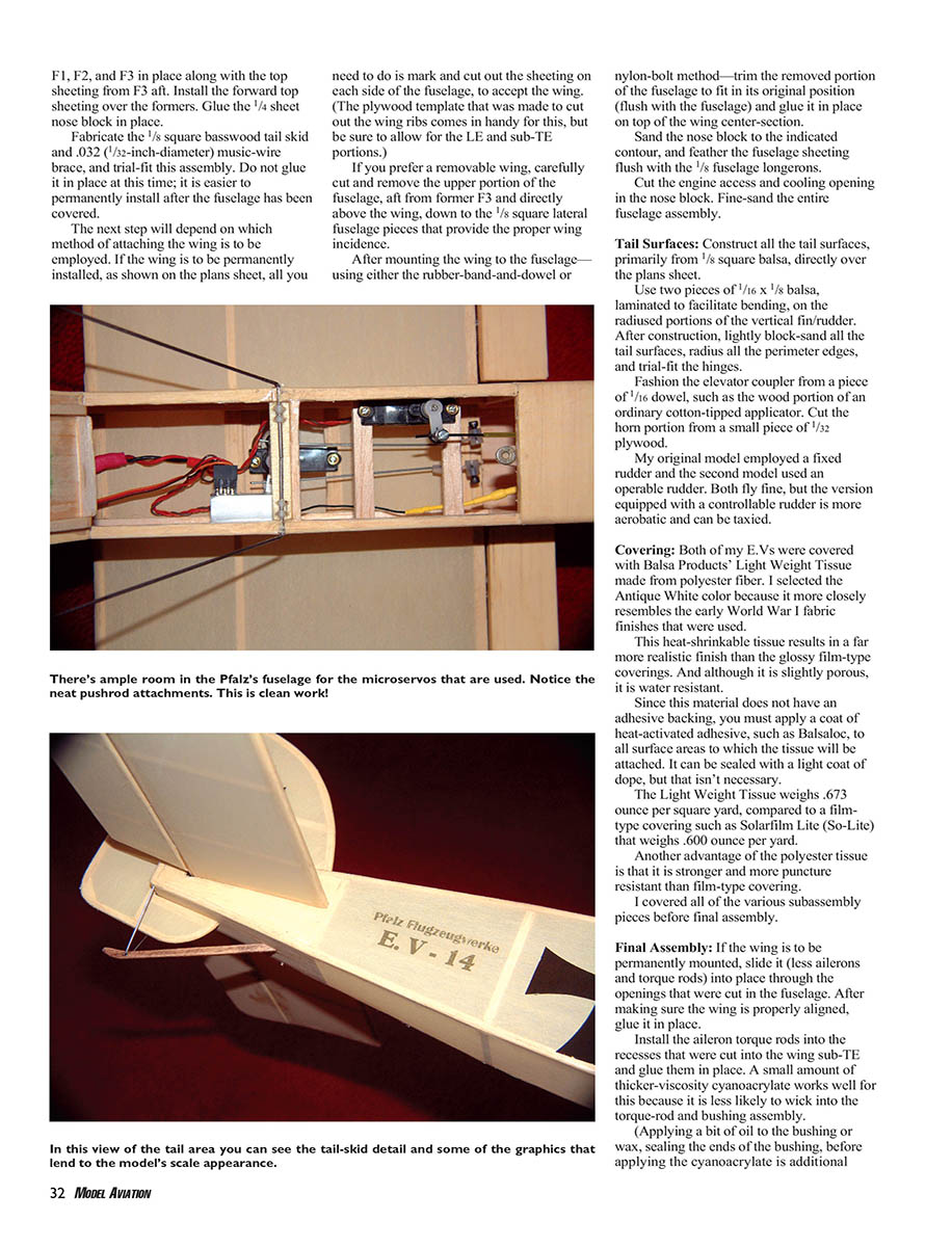
- Install the motor, speed control, servos, and all the radio components, making sure to route the pushrods and servo leads neatly.
- Balance the airplane at the CG location indicated on the plans.
(Note: The scanned plans page contains only the full-size plans and drawing labels for the Pfalz E.V. There is no continuation of the article prose beyond the prior page.)
Pfalz E.V — Specifications
- Type: Sport scale
- Ready-to-fly weight: 7.8 ounces
- Wingspan: 39.75 inches
- Wing area: 258 square inches
- Recommended motor: Small outrunner type (direct drive), brushless
- Control functions: Rudder, elevator, ailerons, throttle
- Elevator throws: 1/2" up and down
- Aileron throws: 1/4" up and down
- Rudder throws: 7/8" left and right
- Side thrust: 0°
- Downthrust/upthrust: 0°
- Incidence: Stabilizer 0°; wing 2° (built in)
- Construction: Balsa and poplar plywood
- Covering/finish: Balsa Products Light Weight Tissue (polyester)
To dress up my model a bit I installed a pilot bust and a machine gun. The pilot was made from hollowed-out rigid foam and weighed 1.8 ounces. The 0.05-ounce machine gun was fabricated from 1/16" balsa-sheet scraps and a small piece of drafting Mylar.
I cut the black Maltese cross insignia from black Major Decals water-transfer-decal sheet material.
Radio and Power Details
- Transmitter: Airtronics RD8000 (used on both E.V.s)
- Original model: Airtronics microreceiver (item 925152) and Super MicroLite servos (item 94091Z)
- Subject model: GWS R4P Pico receiver and GWS Pico servos
- Motor: Lenz direct-drive (17-turn) brushless motor
- ESC: Castle Creations Phoenix-10
- Battery: Great Planes ElectriFly two-cell 720 mAh Li-Poly pack (item GPMR0810)
- Propeller: GWS 8 x 4 propeller (item EP8040)
- CG: Achieved by positioning the battery pack just forward of the CG point shown on the plans
- Control-surface travel limits: Set according to the dimensions shown on the plans sheet
Ready to fly, my Pfalz E.V weighed 7.8 ounces, producing a wing loading of 4.35 ounces per square foot.
Flying
The E.V. model shown was constructed during what most RC modelers in New England commonly refer to as “The Building Season.” Non-aeromodeling-area residents simply refer to this time of year as “January and February.”
As my age increases, so do the outside-air temperature minimums I consider acceptable for RC flying. Long gone are the days of flying in single-digit temperatures and actually enjoying it, with the transmitter and my hands encased in an insulated mitt.
Fortunately, RC indoor flying sessions have been scheduled weekly in my area at a relatively new sports facility that encompasses three soccer fields. For local modelers these indoor sessions have proven popular and a welcome break from the monotony of cold, snowy, dreary winter weather. With no numbing conditions or wind to contend with, what better place to test-fly the Pfalz?
With the system battery packs fully charged, the preflight check consisted of a radio range check and a quick wiggle of the sticks to ensure that all controls were functioning properly. The takeoff was made from flat artificial turf, which presented an ideal opportunity to assess ground-handling capabilities. I spent a few moments taxiing the E.V. In spite of being equipped with a fixed tail skid, the model’s ground handling was quite good.
I made a smooth takeoff by holding a bit of right rudder and up-elevator while gradually advancing the throttle. The takeoff run was straight and surprisingly short, and it was quickly apparent that the Lenz direct-drive brushless motor was an ideal power choice.
Several blips of down-elevator and one blip of right aileron were the only things needed to have the Pfalz flying nicely. Most of the flight time was at half to two-thirds throttle. At full throttle the airplane will easily loop from straight and level flight, and it is reasonably aerobatic.
Landing the E.V. was easy and uneventful. My initial test flight was seven to eight minutes in duration, and there was still “time” left in the 720 mAh battery pack. Subsequent flights revealed that 12–14 minute flights were easy to attain with judicious use of the throttle. The model flies much like a trainer.
I have flown my E.V outdoors on many occasions with no mishaps. It is a fun airplane to fly that performs well even in less-than-calm air conditions. Wind conditions that allow any of the popular slow park flyers to be used pose no problem for the Pfalz.
Although this model can be flown in mild-breezy conditions, it is ideal for calm-air flying where you can fly it low and slow, only a foot or two above the ground, with complete confidence.
If you are searching for a simple, low-cost, electric-powered sport-scale building project, I hope you find the Pfalz E.V of interest.
MA Bob Wallace bobwrc@sbcglobal.net
Sources:
- Water-Transfer Decals:
- Major Decals
- 21 Fisher Ave., East Longmeadow, MA 01028
- (413) 525-7465
- www.majordecals.com
- ESC:
- Castle Creations
- 402 E. Pendleton Ave., Wellsville, KS 66092
- (785) 883-4571
- www.castlecreations.com
- Todd’s Models:
- Box 827, Snoqualmie, WA 98065
- (425) 888-3201
- www.toddsmodels.com/index.html
Transcribed from original scans by AI. Minor OCR errors may remain.

