
Phoenix
Tom Dixon
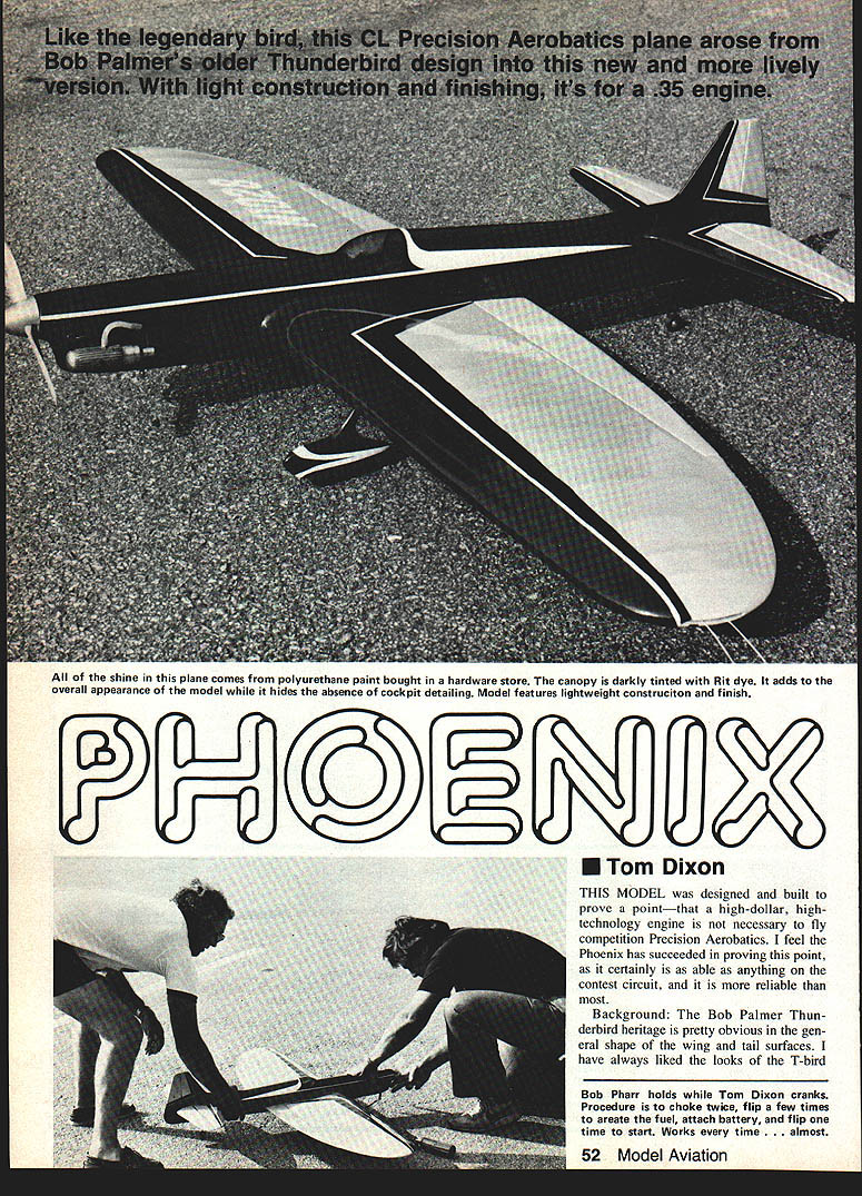
This model was designed and built to prove a point—that a high-dollar, high-technology engine is not necessary to fly competition precision aerobatics. I feel the Phoenix has succeeded in proving this point, as it is certainly as able as anything on the contest circuit, and it is more reliable than most.
Background: The Bob Palmer Thunderbird heritage is pretty obvious in the general shape of the wing and tail surfaces. I have always liked the looks of the T-bird. Wing maneuvers and the semi-elliptical design are highly efficient from an induced-drag point of view. Not only is it pretty, it works better. This wing is very large (by current standards) for a .35 airplane at 56 in. span and an area of 610 sq. in. Were it not for the efficient shape, it would probably be too large.
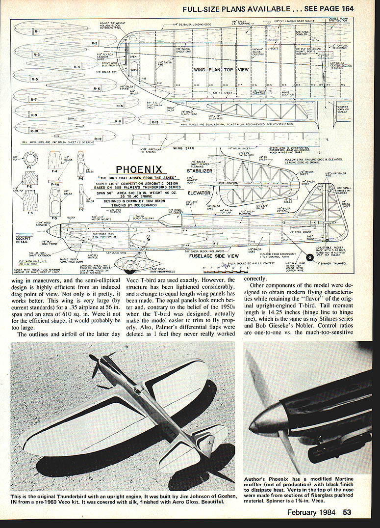
The outlines and airfoil of the latter-day Veco T-bird are used exactly. However, the structure has been lightened considerably, and a change to equal-length wing panels has been made. The equal panels look much better and, contrary to the belief of the 1950s when the T-bird was designed, actually make the model easier to trim to fly properly. Also, Palmer's differential flaps were deleted, as I feel they never really worked correctly.
Other components of the model were designed to obtain modern flying characteristics while retaining the "flavor" of the original upright-engined T-bird. Tail moment length is 14.25 inches (hinge line to hinge line), which is the same as my Stilares series and Bob Gieseke's Nobler. Control ratios are one-to-one versus the much-too-sensitive 3:1 setups used by Bob Palmer in his planes. (Even Bill Werwage and Les McDonald have moved away from the 3:1 set-ups.) The engine is inverted for proper thrust line and vertical C.G. relationship in this version, but the turtledeck fuselage of the original T-bird is maintained.
Credit for the general look of this plane goes to Jerry Ross of Florida, who used to fly an inverted-engine, old-style T-bird with wheel pants similar to mine. Jerry's plane had the smaller wing of the first T-bird, but it flew magnificently. Unfortunately, Jerry lost the plane when it shed a prop blade; it literally shook itself apart. He never built another one, subsequently dropping out of stunt flying. A great loss.
An additional trimming feature I have added is the adjustable rudder, which is held in place by a screw-in-slot arrangement on the bottom of the fuselage. I don't remember where I first saw this method of adjustment, but it's light, clean, and easy to do on any model with the rudder aft of the elevator. The adjustment allows optimum trimming for maximum line tension with minimum drag.
Construction
Wing
I begin with the wing, as this is the heart of the design. If I mess it up, I either quit or have just enough concentration left over to try again. It's discouraging to build all the other components, then build a warped wing! I strongly suggest using an adjusto-jig or similar system to maintain alignment. I really can't imagine building this wing without a jig.
Cut two each of the ribs from the templates shown on the plans. Match each rib to its counterpart on the opposite half. Also, generally eyeball all the ribs to be sure you maintain the proper taper, or step-down, from rib to rib in each half. The spar should also be matched to the pattern on the plans, as it curves (top and bottom) at the ends. Join both halves of the spar before beginning the wing construction.
Once satisfied with the ribs and spar, align the ribs on the jig; add the spar, not yet gluing it completely in place. Add the 3/8 in. trailing-edge cap. I use a wide piece of 5/8 in. for this, having drawn a centerline on the length of it. The trailing edge of each rib is then pinned to the cap, centering on the line and perpendicular to the cap when viewed from above. Once all the ribs are lined up, cement to the trailing-edge cap using CYA glue, then glue the spar to the ribs. The sheet trailing-edge extensions are now added, then the 1/16 in. trailing-edge planking and 1/4 sq. leading edge. Even in the jig, check from time to time that alignment is being maintained.
When the complete wing is shaped and sanded, cut away excess wood in the rib centers, spar bay between the ribs, and in the inboard tip. A Dremel sanding drum is good for this.
Controls and center section
Controls go in next. I use a 3-in. Top Flite nylon bellcrank (having never seen any advantage in the more esoteric systems being proposed lately). The bellcrank seems pretty far aft, but this poses no problem. It was located there to avoid cutting the spar, which would weaken it. Its placement also facilitates installation of the landing gear and adjustable lead-outs. (Bill Netzelberg proved many years ago that bellcrank location was irrelevant as long as the lead-outs didn't bind. It's the location of the lead-out exit that matters.) Use whatever bushing system you like, but do build horns, pushrods, etc., for long life.
I don't add the flaps until I am ready to spray color on the plane. This avoids build-up of paint in the hinge lines.
The lead-out guide is the usual nylon block and slotted plywood mechanism. I use an empty lipstick tube to hold adjustable tie-wrap in the outboard wing. (If you are not married or don't have ready access to discarded lipstick tubes, you probably should try something else; you'd have a heck of a time explaining what you're buying lipstick for!) The wing root block is covered over when the wing is covered, but it can be accessed if extra weight is needed or must be subtracted. It can be covered with Monokote or recovered with paper once the tie weight is right.
Fuselage and tail
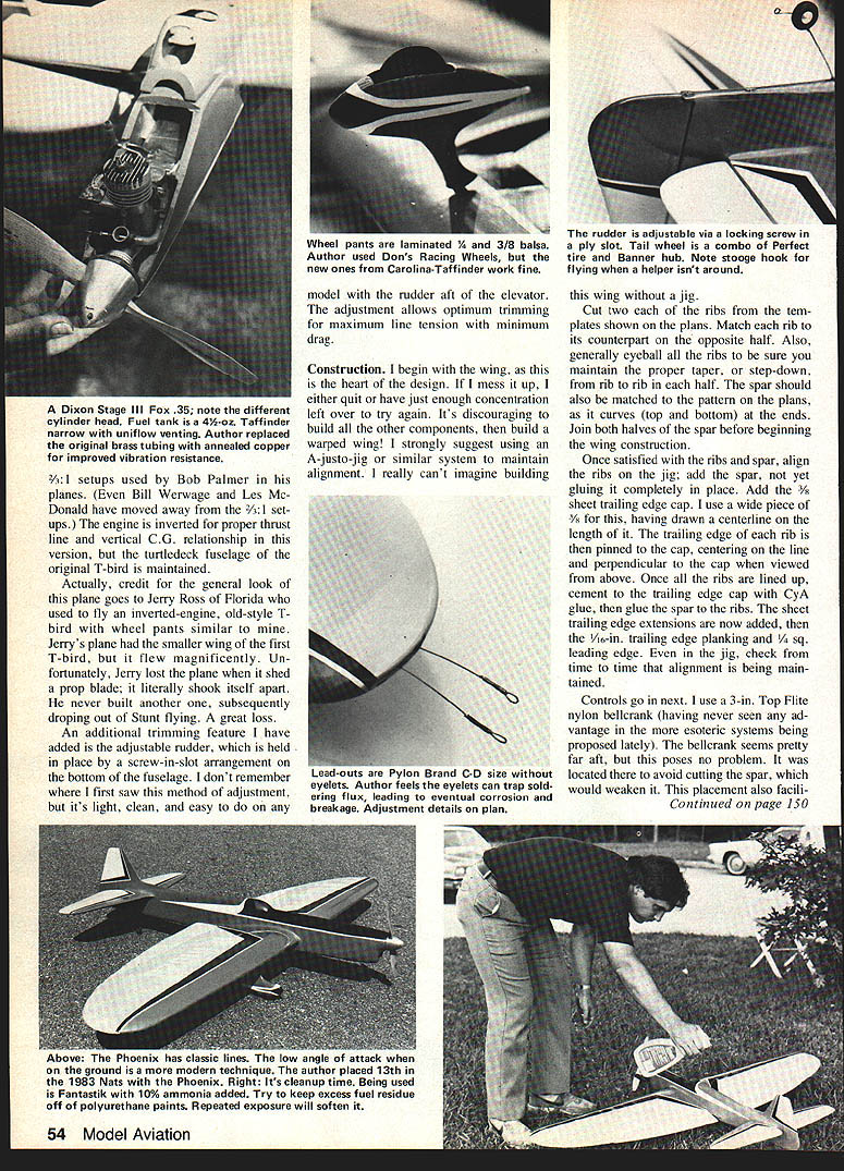
Fuselage construction is very conventional. However, use very light wood throughout. If you feel the sides are not light enough, you can cut out the fuselage sides similar to the way the Nobler is done. Take care to leave enough strength, though. The fuel tank is semi-removable, but I'm beginning to believe this is unnecessary. The main advantage seems to be that the vents aren't in the way during construction of the fuselage. I use a 4-oz. Carolina-Taffinder narrow fuel tank modified with an in-line muffler; the tank is blocked in place with pieces of 1/32 in. balsa held with a drop of CYA glue. This can be cut away to remove the tank if necessary.
All fuselage blocks should be hollowed to approximately 1/8 in. thickness. The Dremel is great for this also.
Tail surfaces are built-up for lightness. I suggest hollowing the horizontal/elevator spars, also, to save a few grams. The geodetic structure allows light wood to be used with no loss of rigidity.
Assembly
Assembly of the main components is the most crucial part of construction other than building the wing straight. I start with centerlines drawn on both sides of the fuselage at the leading and trailing edges of the wing cutout. These lines are matched to the center of the leading and trailing edges of the wing to ensure that no incidence is built in. Once satisfied with runeness on these lines, I then align the fuselage with the wing, looking down on the top of the plane. I measure from tip to centerline over and over, then finally eyeball it in place. Pins and a drop of CYA glue here and there hold the wing and fuselage together while going through this agony.
I don't permanently glue the wing until the stab is similarly mounted and aligned. Even then I may wait several days, then go back and look and measure some more! (I figure it may never be straight, but all the sincere effort can't hurt when you're trying to gain favor with the Stunt gods!) Once satisfied, or tired of the whole thing, the wing is permanently glued with an aliphatic resin and gauze reinforcement on the inside of the fuselage. (Epoxy is not used here for weight reasons.) CYA glue is used around the outside joint. The stab is also permanently glued with aliphatic resin and epoxy or nylon reinforcement. This is later hidden by the fillets at the stab.
Add the tail wheel mount and main wheels. Check to make sure the model will track straight or slightly to the left. Bend the main gear and/or tail wheel strut with Vise-Grip pliers until it rolls properly, then permanently attach the wheels with soldered washers. Add the remaining fuselage structure, fin and rudder, and wheel parts. Start final-sanding everything to shape.
Finishing
In the interest of lightness, a "minimum dope" finish was tried with good results. The bare wood received one coat of brushed Aero Gloss clear, followed by sanding with 320 paper, then two more coats and sandings. At this point the model was covered with Sig Ply-Span tissue applied wet just like silkspan (the Ply-Span is the rubber-moded grade). This received three brushed coats of thinned Aero Gloss clear.
Fillets were added from a mixture of Epoxolite and microballoons, wet-sanded to final shape after they had cured. Aero Gloss clear was then applied to the fillets to provide good adhesion for subsequent coats of Sig products.
Filler coats of Sig Lite-Coat clear with talc added were applied, but not on the open bays of the wing and tail—only on the solid wood surfaces. These were wet-sanded with 400 paper. No attempt was made to completely fill all the grain.
A light coat of Sig silver was then sprayed on as a base for the color. The main color I chose was light gray—for its flaw-hiding properties. To get a little color and excitement in the overall appearance, the trim is in red-orange, white, and black.
The clear top coat is Liquid Plastic polyurethane spray made by Carver-Tripp that is available in hardware and home supply stores (try the Home Department). This looks like Imron when it is applied, but it is much less expensive and doesn't have Imron's toxic properties. The Liquid Plastic is left as it is sprayed on, without being rubbed out. Experiment a bit first before spraying on the airplane, and allow at least a week for it to cure before flying, to be sure that it will be fuel-proof.
This finishing system worked very well for me, and it turned out to be a major factor in achieving a lightweight model. However, I don't think I will ever get 20 appearance points from it! The finished flying weight is 44 oz.
When this was written, with only 15 or so flights on the model, it was trimmed out. A 10-6EW Rev-Up prop has been used for all flying so far, but I am considering the use of an 11-5W Rev-Up to allow the engine to run a little faster without increasing flying speed. Lap times are 5.5 to 6 sec. on 62-ft. lines with a new Fox .35 engine having many Stage III modifications and a lightened Martine muffler. (Editor: These modifications involve fitting, tapping, new needle-valve assembly, balanced crankshaft, high-compression cylinder head, etc.)
I think you will find the Phoenix to be a fine blend of the old and new.
Transcribed from original scans by AI. Minor OCR errors may remain.

