
Photon Servos
By George Gibson
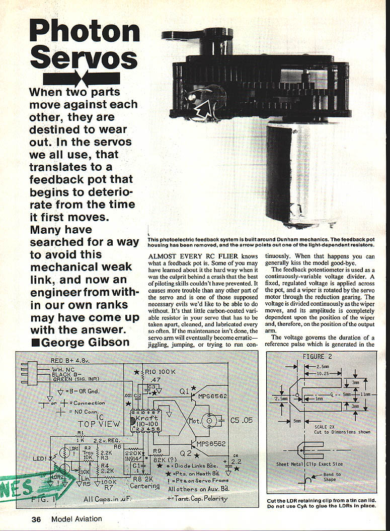
When two parts move against each other, they are destined to wear out. In the servos we all use, that usually translates to a feedback potentiometer that begins to deteriorate from the time it first moves. Many have searched for a way to avoid this mechanical weak link. An engineer from within our ranks may have come up with the answer: the photon servo — a photoelectric feedback system that replaces the feedback pot with an LED and light-dependent resistors (LDRs).
Background: the feedback pot problem
Almost every RC flier knows the feedback pot. It is that little carbon-coated variable resistor in your servo that must be taken apart, cleaned, and lubricated periodically. If maintenance is neglected, the servo arm becomes erratic — jiggling, jumping, or running continuously — and that usually ends badly for the model.
The feedback potentiometer is used as a continuously variable voltage divider. A fixed regulated voltage is applied across the pot, and a wiper is rotated by the servo motor through the reduction gearing. The voltage at the wiper depends on its position and thus on the output arm. That voltage governs the duration of a reference pulse generated in the receiver and compared with the incoming control pulse. If the two pulses are identical they cancel and the servo stops. Any irregularity in the carbon-surfaced pot element — and wear from the sliding wiper — causes malfunctions. Tiny bits of wiper metal deposited on the element make it behave erratically. This has been a persistent nuisance since the inception of proportional RC.
Early alternatives
- Kraft Systems experimented with replacing the feedback pot by using a variable capacitor in the reference pulse generator. That was an improvement but had its own problems, especially as servos got smaller; variable capacitors could not be made small enough.
- Carbon-button wiper contacts were another improvement, but if the button popped out of the wiper arm the results could be catastrophic.
- In the late 1960s John Cline (F & M Electronics) developed a variable-inductance servo and earlier experimented with photoelectric feedback using filament lamps, but filaments were impractical — vulnerable to vibration, burnouts, excessive battery drain, and high cost.
The arrival of LEDs and small transistor-sized photocells (LDRs) made the photoelectric concept practical. Heathkit’s Thumb-Tac photoelectric tachometer, using LDRs, proved the detectors were viable for RC applications.
Photon-servo development
My experiments began with the idea of substituting LDRs for the feedback pot in the existing reference pulse circuitry. Early attempts revealed issues with linearity and reliability when simply swapping an LDR for the pot or placing LDRs in different parts of the circuit. Several insights and innovations followed:
- Two LDRs in series can replace the feedback pot if they are carefully matched; the junction corresponds to the pot wiper.
- An LED is the only viable light source: small, vibration-resistant, low current, and with no filament to burn out.
- A movable light source works but requires flexible leads or sliding contacts that may break.
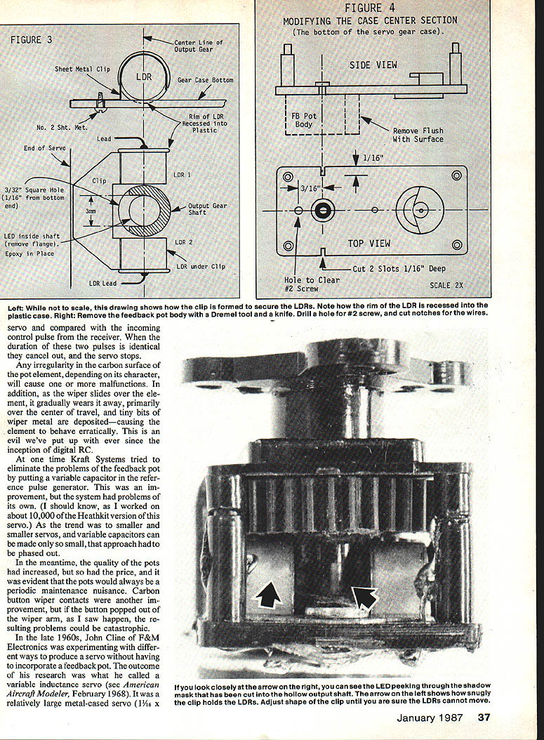
- A movable shadow mask between stationary light source and detectors avoids sliding contacts and flexed leads.
- Using a servo with the output gear arrangement that leaves space under the output gear (Dunham D-1) allowed room in the gearbox for a shadow mask and the photoassembly.
- Initial masks were anodized aluminum glued to the output shaft and used two LEDs. Later I put a single LED inside a hollowed output shaft, carving a recess to project light onto the two stationary LDRs alternately as the shaft rotated.
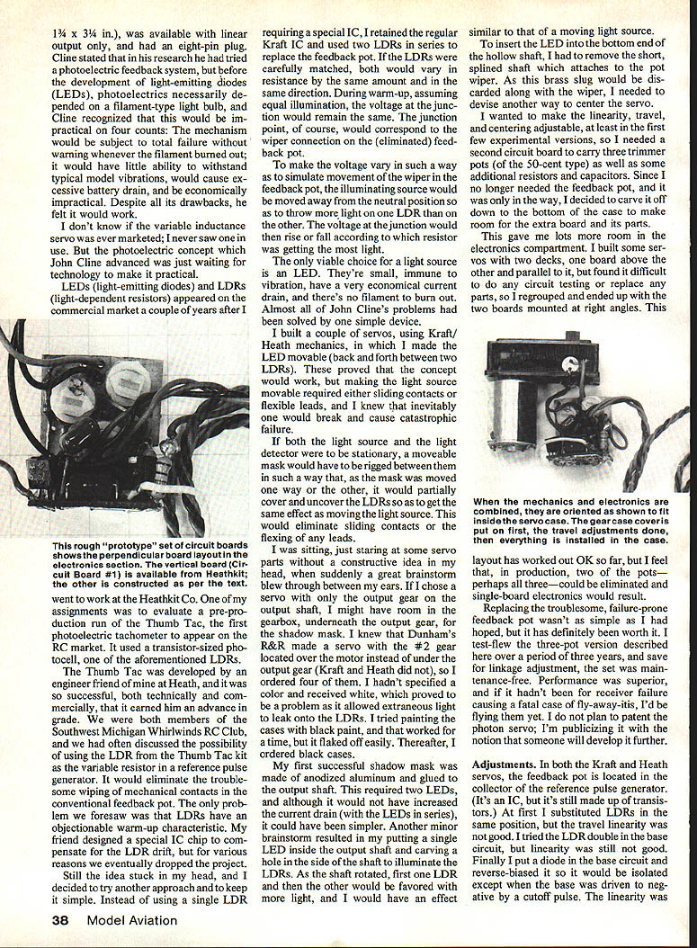
To make room for the additional electronics (three trimmer pots and some resistors/capacitors) I removed the feedback pot body molded into the servo center section and added a second circuit board. I experimented with board layouts and mounted a two-board assembly at right angles, which worked well for testing.
After building and test-flying three-pot versions for three years, the photon servo proved reliable and maintenance-free (aside from linkage adjustments). Field performance was superior. I do not plan to patent the photon servo; I publicize it hoping someone will develop it further.
Adjustments and circuit changes
- In both Kraft and Heath servos the feedback pot is located in the collector of the reference pulse generator. Early LDR substitutions in that location gave poor linearity. Placing a diode in the base circuit and reverse-biasing it so it is isolated except when the base is driven to negative by a cutoff pulse produced better linearity.
- With no mechanical pot, centering must be adjustable. I replaced the 1K load resistor in the collector circuit with an inexpensive 2K pot for centering.
- A small change in light intensity on the LDRs produces a larger change in junction voltage than the equivalent rotation of a feedback pot. Resistors R2, R3, and R4 (in my design) form a network to attenuate that voltage so the output arm can rotate farther before the control voltage reaches the stop value. R2 is the trimmer used to adjust servo travel.
- Mounting LDRs with cyanoacrylate (CyA) caused failures in some versions. Units with LDRs held by wire clips worked fine; adding CyA later caused failures. I now recommend sheet-metal retaining clips made from a tin can lid and securing the LDRs with CyA only to the clip if desired.
- Current draw: at neutral, the two LDRs draw about 0.3 mA and the LED about 0.5 mA (roughly 0.8 mA total). The original feedback pot drew about 1.3 mA. Compared with typical servo idle currents (~20 mA) and loaded currents (150 mA+), the extra photon-servo draw is insignificant. In three years of testing I experienced no battery-drain problems.
Construction notes:
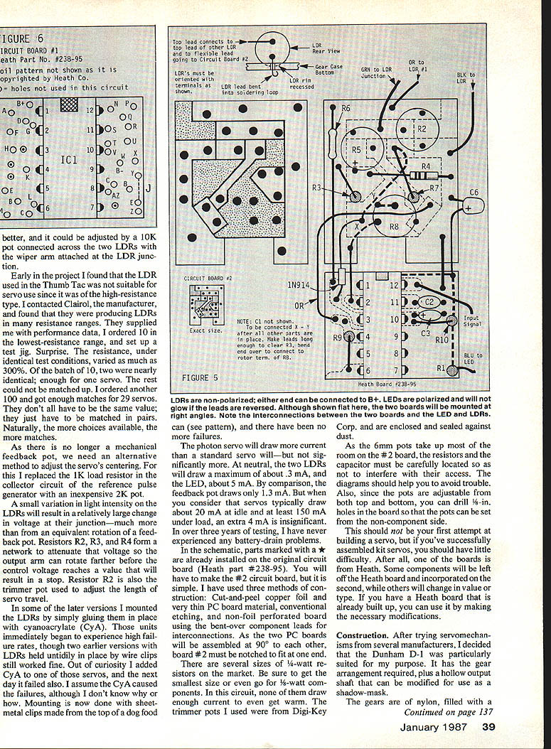
- Parts marked with an asterisk in the schematic are already on the original Heath circuit board (part #238-95). You will have to make the #2 circuit board.
- I used three construction methods for the #2 board: cut-and-peel copper foil, conventional etching, and non-foil perf board using bent-over component leads.
- Use the smallest available 1/4-watt resistors (or 1/8-watt) because space is tight. Trimmer pots used were sourced from Digi-Key.
- The Dunham D-1 servo is particularly suited: it has the required gear arrangement and a hollow output shaft that can be modified as a shadow mask.
Construction: mechanical assembly
- Disassemble the servo completely; do not lose small parts or gear pins.
- The output gear is attached to the wiper rotor by a splined brass shaft. Carefully pull the gear upward to separate it from the shaft. The splined shaft and pot wiper are not used in this project and may be discarded.
- The feedback pot body is molded into the servo center section. It can be split into several segments and sawn off individually (a Moto-Tool cutoff wheel works well). Carve the stumps flush with a sharp X-Acto knife. Make two 1/8-in. slots with the cutoff tool and drill the hole to clear the #2 screw.
- Select a wide-angle red LED that fits inside the bottom end of the output gear shaft. Sand off the flange so the LED inserts deep enough but still turns freely. Assemble the output gear temporarily with the LED leads extending down through the bearing hole.
- Pull the LED down firmly by its leads and place a drop or two of 5-minute epoxy in the bearing hole around the leads. Do not use CyA here. Let the epoxy set firmly, then remove the top section and output gear.
- Make the retaining clip for the two LDRs from the top of a tin can (or suitable thin spring brass/bronze). The clip must be thin and strong. Dimensions are given in the illustrated figures (referenced in the original).
- LDRs have a rim that prevents them from laying flat. Do not grind the rim. Instead, use a defunct metal-cased transistor of the same diameter as the LED; mount it in the retaining clip and heat the LDR rim with a soldering iron until the plastic rim softens and sinks slightly. Be careful with heat to avoid ruining the plastic.
- Mill a recess into the case so the LDRs sit flat and are held by the retaining clip. Bend the bottom lead of each LDR downward through the 1/8-in slots; bend the other lead forward and join the two (they can be soldered to the retaining clip). This junction is where the green wire from board #2 will later be soldered.
- Identify the LED leads: connect a flight battery positive through a 1K resistor and the negative directly; touch them to the LED leads. If the LED lights, the side with the resistor is the anode; the other is the cathode. Bend the cathode lead flat and solder it to the LDR2 lead that comes through the slot. The black wire from board #2 will later connect here.
- Create the shadow mask: on the bottom side of the output gear there is a neutral-point ridge. Scribe a line on the shaft from the center of this ridge toward the shaft bottom. At 1/16 in. from the bottom end, make a tiny punch mark and drill a hole through the shaft wall (start with 5/64-in., finish with 3/32-in.). Don’t drill through both sides. Square up the hole with an X-Acto blade. This hole and recess form the shadow mask that alternately shades the two LDRs as the shaft rotates.
- Reassemble the gear train and top cover. Tape the cover temporarily so no external light leaks into the gearbox while the case bottom is off.
- Shorten the LED anode lead and make a solder loop for the blue wire from board #1. Do not install the motor yet. Rotate the gears so the output gear is at neutral and put the output arm on the shaft at neutral (leave the arm retaining screw out). With power applied later you should see a red glow through the top of the hollow shaft.
Circuit board assembly (overview)
Board #1: the original Heathkit board (part #238-95)
- If using a preassembled Heath board, leave these parts on the board: power transistors, motor leads, servo cable with plug, the 1.0 µF (or 2.2 µF) tantalum capacitor, the 0.47 µF tantalum capacitor, the 0.001 µF ceramic capacitor, and the IC. Remove all other parts by clipping them off flush with the board and unsoldering the stumps.
- If starting with a new board, mount the IC first, orient it correctly so pin #1 connects to the +4.8 V foil pad.
- Connect the servo cable (red, black, green, white): red to B+ nearest pin #1 of the IC; black to B-; green to N (pin #12 area). If the white wire is present, strip and save it for later use.
- Install two MPS6562 transistors (observe EBC lead order) keeping them close to the board (≤1/8 in. height).
- Install the 0.47 µF tantalum capacitor (plus lead to hole T, minus to U) and the 0.001 µF capacitor at R and S.
- Install a 100K resistor (R10) standing vertically from X to Y. The 1.0 µF (or 2.2 µF) tantalum capacitor destined for X-Y will be installed later.
- Install the 82K resistor at K-L (value may be adjusted during tuning).
- Replace the original part at F/H with a 1N914 diode at F; the banded end should be down and the diode’s positive lead left long for connection to board #2.
Board #2: your added trimmer and attenuation circuitry
- Check the board for shorts with an ohmmeter (R × 1,000). Cut any foil bridges with an X-Acto knife.
- Install two 10K trimpots on the non-foil side so they stand about 3/16 in. high.
- Install R6 (220K) along the left side of the board; position it to act as an insulator against the bare lead of R3.
- Install two short bare wires opposite the clearance notch at the board end. One will connect #2 ground foil to #1 ground (B-); the other will connect #2 +2.2 V foil to the IC’s +2.2 V point.
- Install R3 (2.2K) standing vertically and route its bare lead under R6. Install R7 (100K).
- Install C6 (2.2 µF dipped tantalum) with the negative lead to the board; leave the positive lead long for later connection to board #1.
- Cut a 1-1/4 in. length of stranded orange wire, prepare the ends, and solder one end to the foil pad shown in the schematic.
- Cut 2 in. lengths of blue, black, green, and orange wires and prepare them; connect white to the top of R1 on board #1; connect green, black, and orange to board #2 as shown in the assembly diagram.
- Mount board #2 at the proper end of board #1 so the components overhang; the two boards should form a right angle and the notch on #2 should fit over the IC end. Bend the short bare wires on #2 down into vacant holes on #1 to connect grounds and the +2.2 V point.
- Feed the positive lead from the 1N914 diode through hole X on board #2, cover it with Teflon tubing, bend and solder it to the foil pad where R7 connects. Clip excess lead.
- Install the 0.1 µF polyester capacitor (C1) at X and Y; solder one lead to the diode lead. Bend the Y lead to the wiper terminal of pot R8.
- Connect the 1-1/4 in. orange wire to hole H.
- Cut two wires (brown and white) 1-1/2 in. for the motor connections: brown to hole M, white to hole AZ. Later connect white to the motor red (positive) terminal and brown to the other motor terminal. Install C5 (0.05 µF ceramic) across the motor terminals with insulated lead to the red terminal.
- Except for the photoelectric assembly connections, the board work is finished.
Photoelectric assembly wiring:
- Black wire to the junction of LED and LDR leads (LED cathode-LDR2 junction).
- Green wire to the junction of the two LDRs (pot wiper equivalent).
- Orange wire to the remaining LDR lead.
- Blue wire to the LED anode.
Testing and final adjustments
- With the motor removed so the gear train is not engaged, place the servo unit in the case and install the input gear, output shaft, and top cover. Tape the cover temporarily to prevent light leaks.
- Hook the servo to a receiver and battery. The LED should light; if not, reverse the battery connection or check solder joints and component placement.
- With motor out and receiver on, the motor should not run (a twitch may occur). If the motor runs continuously, there is a construction defect — unplug and inspect for solder bridges or misplaced parts.
- If the unit is OK, turn on the transmitter. The motor will most likely run in one direction and not stop until adjusted.
- Shut the receiver off. Set the travel pot (R2) to its extreme right (maximum travel) for initial settings.
- Ensure transmitter and receiver are on. Set the servo arm at neutral. Adjust the centering pot (R8) until the motor either stops or oscillates. Shut off the receiver, engage the motor and gear train, then turn the receiver back on.
- If the output arm runs to one side and won't come back, reverse the motor leads and start over.
- If the arm oscillates with correct motor polarity, readjust the travel pot (try mid-range) and adjust linearity pot (R5) so the arm rests centered. Check for approximately 45° travel each side of center. Travel, linearity, and centering interact; adjustments may require several iterations. Don’t expect perfect behavior immediately.
- If the finished servo oscillates, try changing R9 from 82K to 68K or 56K. If it seems underpowered, try 100K or 120K. Small changes will require recentering.
- Note: with large, rapid stick inputs under no-load conditions the servo may overshoot and return immediately due to the LDRs’ response lag to sudden brightness changes. In typical model use with load, this is usually not a problem.
Notes and further work
- It may be possible in later designs to eliminate one or more trim pots; however, a centering pot (2K) will likely remain necessary.
- I envision a unit where the lower part of the output shaft (shadow mask) could be independently adjustable relative to the output gear via a friction adjustment accessible from the top of the servo. This would require delicate machining.
- I attempted to adapt the photoelectric concept to the Signetics NE544 IC. One servo operated perfectly by itself, but when used with other servos it caused buzz, jam, and oscillation in the group. The Signetics chip is attractive because it doesn’t require external transistors (smaller and lighter), and I am continuing experiments.
Contact
If you have questions or comments, write to: George Gibson RR 1, Box 157 Fountain, MI 49410
Transcribed from original scans by AI. Minor OCR errors may remain.

