
Pilatus Turbo-Porter
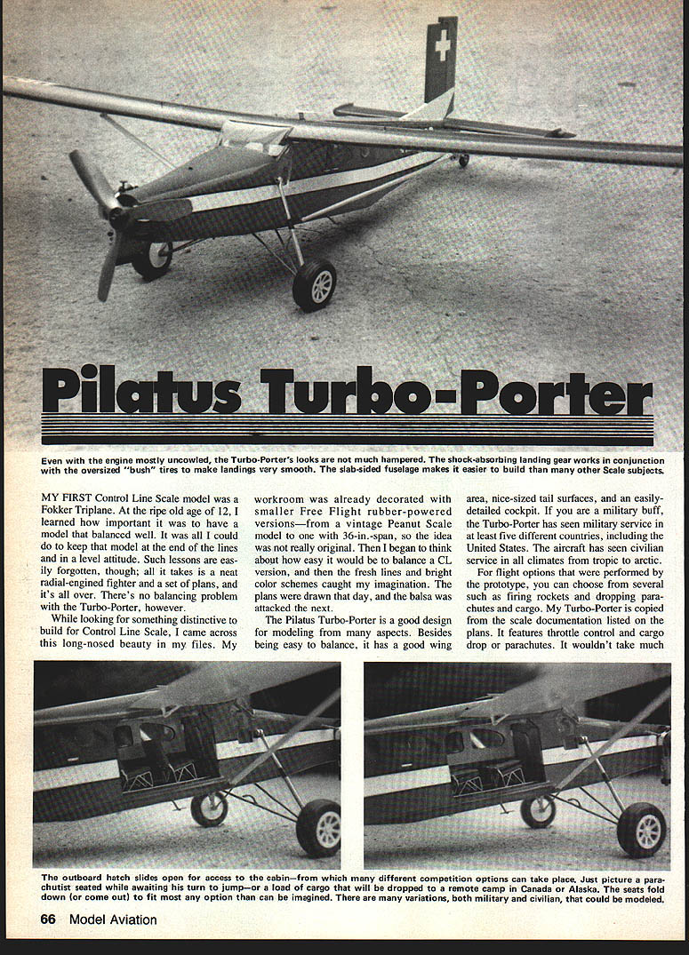
Even with the engine mostly uncowled, the Turbo-Porter's looks are not much hampered. The shock-absorbing landing gear works in conjunction with the oversized "bush" tires to make landings very smooth. The slab-sided fuselage makes it easier to build than many other scale subjects.
My first Control Line (CL) scale model was a Fokker triplane. At the ripe old age of 12 I learned how important it was to have a model that balanced well. It was all I could do to keep that model at the end of the lines and in a level attitude. Such lessons are easily forgotten, though; all it takes is a neat radial-engined fighter and a set of plans, and it's all over. There's no balancing problem with the Turbo-Porter, however.
While looking for something distinctive to build for Control Line Scale, I came across this long-nosed beauty in my files. My workroom was already decorated with smaller Free Flight rubber-powered versions — from a vintage Peanut Scale model to one with 36-in. span — so the idea was not really original. Then I began to think about how easy it would be to balance a CL version, and the fresh lines and bright color schemes caught my imagination. The plans were drawn that day, and the balsa was attacked the next.
The Pilatus Turbo-Porter is a good design for modeling from many aspects. Besides being easy to balance, it has a good wing area, nice-sized tail surfaces, and an easily detailed cockpit. If you are a military buff, the Turbo-Porter has seen military service in at least five different countries, including the United States. The aircraft has seen civilian service in all climates from tropic to arctic. For flight options performed by prototype aircraft, you can choose from several such features as firing rockets, dropping parachutes, or carrying cargo. My Turbo-Porter is copied from the scale documentation listed on the plans. It features throttle control and a cargo drop or parachutes.
Proportions of the prototype are ideal for modeling in several categories. It suits a Control Line-sized .25 engine. Depending upon the builder's desires and capabilities, it can have simple detailing and be a great fun flier, or it can be given full treatment for competition. Dave Haught's effort adds flaps, lights, and airframe detailing readily adaptable to whatever you can dream up.
Construction
Did I mention the Turbo-Porter is also a fast, easy build? Flat fuselage sides and angular lines make construction a breeze. Nonetheless, scale models require a bit of planning; conventional model details you want to include should be planned in advance. Choose the particular version to build and select the options you desire; plan accordingly. For instance, lights will require wires and routing holes. Think ahead — you'll save yourself a lot of headaches later.
Tail assembly
This is a good place to start. Pin down the precut 1/16" sheet planking, cement the spars and ribs in place, and dry-sand well; a sanding block eliminates high spots. Glue the top sheeting and set it aside. The stabilizer, elevator, rudder, and fin share the same type of construction; use cyanoacrylate (CyA) glues since they can be finished very quickly.
- Join the elevators with the control-horn assembly, making sure the halves are flat and properly spaced at the center.
- Dry-fit and add tip blocks; they should be medium-hard stock since they hang out in the breeze.
- Cut out plywood stabilizer tip plates and fit them to the stabilizer, ensuring proper clearance between the elevator balance and the tip plates.
- When satisfied, finish-sand parts and connect nylon hinges.
The rudder and fin are built the same manner. Use tin or brass sheet hinges; the rudder can be set to help line tension in flying. Give the tail assembly three coats of dope, lightly sanding between coats. Cover with lightweight Silkspan. Add aluminum trim tabs by carefully slitting the trailing edges with a small knife and slipping them in place; a coat and filleting with CyA glue will keep them in place. Be sure to round off corners slightly so they will not snag on things.
Wing
Begin by cutting out all the pieces. A key part of the assembly of the entire model is the wing-root spar and bellcrank-mount unit. These parts should be accurately cut to fit together tightly. Join the two spars and the bellcrank mount together on a flat surface using white glue. Let the assembly dry completely before moving it.
- Pin the bottom sheeting to the building board; add bottom spars and ribs, then top spars.
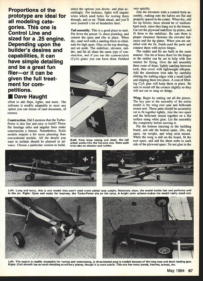
- Fit the root spars and add sheet webs and side plywood spars, and glue. The long, boxy model won't need much added nose weight.
- While the wing is still on the board, fit the root spars, and add the sheet webs to each side of the plywood spars. Do not glue in the plywood spars at this time; we are building a box for each to slide into later.
- Run the lead-out wires through the inboard wing, and plank the top of the wing while it is still pinned down.
- After the wing is dry, lift it from the board, sand, and add the leading edge blocks and tip plates. Sand the entire wing carefully. Fill any holes and voids, sand, and give three coats of clear dope.
The flaps and ailerons are built in the same manner as the tail assemblies. You may find it easier to build them as one piece, then cut them to the right lengths after sanding. Sand them well and apply three coats of clear dope. Cover all the wing parts with lightweight Silkspan and set aside.
Mount the bellcrank assembly to the plywood wing spar unit. Fit the flexible push-rods as shown on the plan, but do not glue them in place yet.
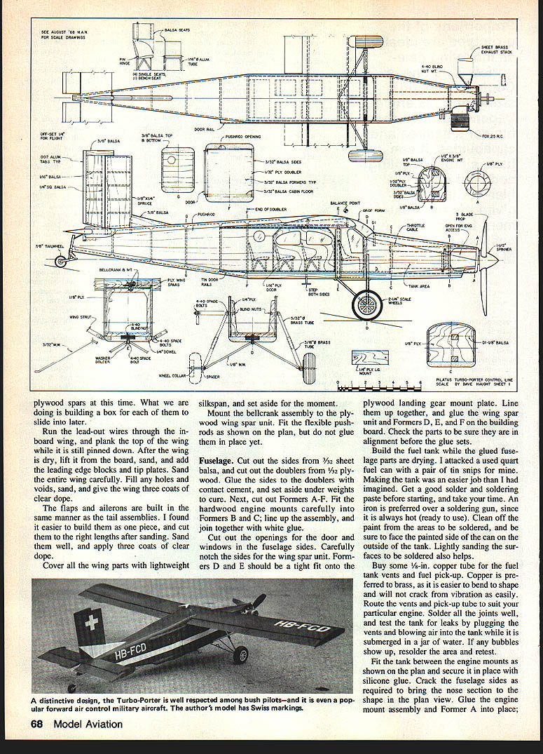
Fuselage
- Cut out the sides from 3/32" sheet balsa, and cut the doublers from 1/32" plywood. Glue the sides to the doublers with contact cement, and set aside under weights to cure.
- Cut out Formers A–F. Fit the hardwood engine mounts carefully into Formers B and C; line up the assembly and join together with white glue.
- Cut out the openings for the door and windows in the fuselage sides. Carefully notch the sides for the wing spar unit.
- Formers D and E should be a tight fit onto the plywood landing gear mount plate. Line them up and glue the wing spar unit and Formers D, E, and F on the building board. Check alignment before the glue sets.
Build the fuel tank while the glued fuselage parts are drying. I attacked a used quart fuel can with a pair of tin snips for mine. Making the tank was an easier job than I had imagined. Get a good solder and soldering paste before starting, and take your time. An iron is preferred over a soldering gun, since it is always hot (ready to use). Clean off the paint from the areas to be soldered, and be sure to face the painted side of the can on the outside of the tank. Lightly sanding the surfaces to be soldered also helps.
Buy some 1/8" copper tube for the fuel tank vents and fuel pick-up. Copper is preferred to brass, as it won't crack from vibration as easily. Route the vents and pick-up tube to suit your particular engine. Solder all the joints well, and test the tank for leaks by plugging the vents and immersing the tank in a jar of water. If any bubbles show up, solder the area and retest.
Fit the tank between the engine mounts as shown on the plan and secure it in place with silicone glue. Crack the fuselage sides as required to bring the nose section to the shape in the plan view. Glue the engine mount assembly and Former A into place. After the glue has dried, pull the tail post together and add the sheet rear formers.
Purchase a quantity of spade bolts from your local hobby shop. Bend and install the main landing gear struts. Add soldered washers to center and retain the wires as shown in the fuselage sections. Bind and solder the ends of the struts together, and add a drop of solder to the spade bolts and nuts that hold in the gear.
Install the shock-strut mounting spade bolts and blind nuts to Former D. Fabricate the struts from the indicated sizes of brass tube by flattening the ends with pliers as shown. Small springs installed into the tubes give the units a bit of shock-absorbing action. Attach the upper end of the struts with 4-40 bolts and nuts. The lower end slides onto the landing gear wire and is retained by a short tubing spacer that is soldered in place.
This is the time to build and install the cockpit interior. Cement the floor and ceiling in place first. While these are drying, build the seats, instrument panel, rudder pedals, and stick. The scale source listed on the plan gives good interior details. Don't forget to detail your model to match the purpose you intend it to portray. My Turbo-Porter is fashioned after the Swiss version on the scale details. I finished the cabin interior with three colors of contact paper — a handy material since it looks like the vinyl used in the full-size plane and is self-adhesive. The seats were made from balsa and glued to aluminum tube frames; they hinge down like the prototype to make room for more cargo.
Each seat was equipped with lap belts made from contact paper and aluminum foil. Epoxy the seats in place when you are finished with the rest of the interior. The front seats are bucket type; they are built similar to the cabin seats but with a sheet balsa base. The rudder bar and stick are made of 3/32" aluminum tubing.
Everyone seems to have a favorite way to build instrument panels, so copy the panel on the scale drawings and use the instruments you prefer. Mount the panel to Former D1 and install it onto the nose of the model.
Assembly
- Glue on the stabilizer and elevator assembly, and run the pushrods to the tail and nose.
- For flexible pushrods, be sure to anchor them well and at short intervals to prevent flutter.
- Add the bottom ribs, hollowing them after they are fitted to save weight. Glue them in place and sand them to the contours shown in the cross sections.
- Cut away the nose area and install the engine, throttle hookup, and blind nuts for the engine and scale exhaust. When the linkage works smoothly, anchor the pushrod guides, and plank the top and bottom of the nose.
The wing panels can now be slid onto their respective spars and fitted to the fuselage. Hook up the lead-outs and solder them as per the drawings in the AMA rule book. Slide off the wing panels, fill the wing-spar holes with epoxy, and slide the panels back on. Align them carefully, and block the whole assembly in place while the glue sets. The top block can now be fitted, hollowed, and glued on.
Add the rudder assembly along with the dorsal fin. Cut out the cabin door and give it a few coats of clear dope to fill the grain. Finish the inside of the door to match the cabin interior. Bend the door rails from tin or brass and install into grooves cut into the fuselage side. Make sure the door slides easily in its track, and glue the tracks in place with epoxy.
Build the wing struts as shown on the plan. Fasten the upper end to the spade bolt in the wing with a small 4-40 bolt and nut. On the fuselage end, drill a 1/4" dia. hole into the bottom block of the fuselage. Cut a short length of 1/4" dowel, and drill it to hold the spade-bolt anchor. Epoxy the spade bolt to the dowel, and when it has set, insert it into the hole in the fuselage; glue well, and when dry, pilot the bottom end of the strut in place.
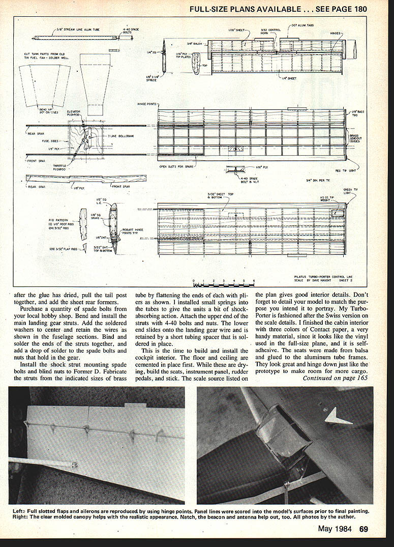
Cut the windows from 1/32" clear plastic. Install them with silicone glue. Carve a mold for the windshield and heat-form it from thick plastic. Do not install the windshield until after the model is finished.
Give the fuselage three coats of clear dope, and cover it with Silkspan. Build the tail-wheel assembly from brass tube and sheet, and install it with epoxy.
Attach the flaps and ailerons next. Note the use of nylon hinge points to mount them.
- Drill holes at the desired angle into the flaps and the wings.
- Tape the flaps and ailerons in place, spacing them out from the wing and fuselage as well as 1/32" from each other.
- In each hole place a drop of epoxy and then the hinge. Check that the angle is the same for all hinges by sighting down the wing from the tip. Adjust as required.
- When the epoxy has set, remove the tape.
- Pin the controls in place — preferably neutral (0°) for the flaps, 1/32" down for the inboard aileron, and 1/32" up for the outboard aileron. This will help keep the Turbo-Porter level in flight.
Give the model several coats of clear dope, sanding between coats, until the finish is smooth and ready for paint. Mask off the windows, and begin painting. After the paint has cured, go back and add the trim paint and any details you desire.
Balance the model — you may be surprised. Mine took 1/2 oz. of tail weight to bring it into balance. Bind and solder the lead-out ends, adjusting to fit your handle. Check for proper throttle and control movement.
Flying
This is the true test of a model. Pick a calm day, and proceed methodically. Tune the engine, adjust the throttle for smooth response, and time the length of engine run. Keep notes of the details for future use.
The Turbo-Porter is a smooth flier. Its distinctive lines in the air are impressive. I hope you will enjoy your Turbo-Porter as much as I have enjoyed mine. Just watch those landings in the grass; the long nose makes three-point landings mandatory!
Sport Scale Competition Suggestions
Thinking of Sport Scale competition? Add rivets, more doors, cargo drops, brakes, lights, etc., and you should do very well.
Transcribed from original scans by AI. Minor OCR errors may remain.

