
Pink Lady Formula "40"
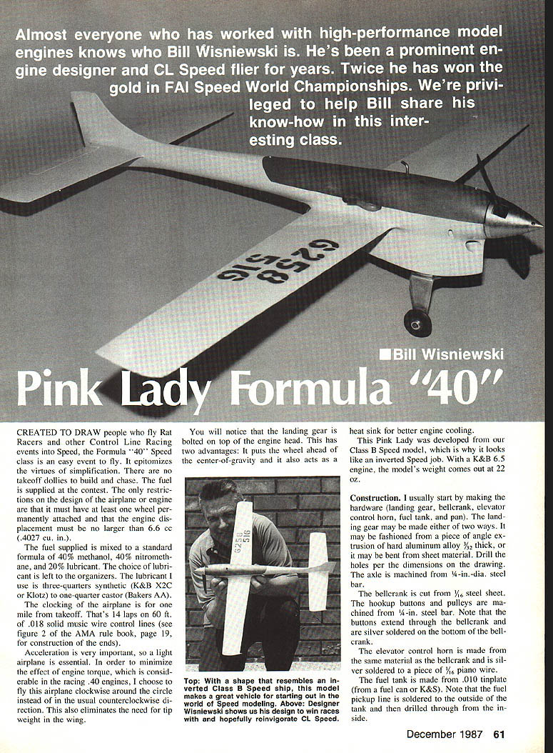
Almost everyone who has worked with high-performance model engines knows who Bill Wisniewski is. He's been a prominent engine designer and control-line (CL) speed flier for years and has twice won gold in the FAI Speed World Championships. This article shares his know-how for the Formula "40" class.
Introduction
Formula "40" (Speed 40) was created to draw pilots of Rat Racers and other control-line racing events into Speed. It is an easy event to fly and epitomizes simplification: no takeoff dollies to build or chase, and contest-supplied fuel under standard restrictions. The Pink Lady was developed from a Class B Speed model and resembles an inverted speed job. With a K&B .40 engine (≈6.6 cc) the finished weight is about 22 oz.
Rules and Fuel
- Engine displacement: no larger than 6.6 cc (0.4027 cu. in.).
- The airplane and engine must have at least one wheel permanently attached.
- Fuel: standard Formula "40" — 40% methanol, 40% nitromethane, 20% lubricant.
- Choice of lubricant is left to organizers.
- Recommended lubricant: 3/4 synthetic (K&B X-2C or Klotz) + 1/4 castor (Baker's AA).
- Clocking: by airplane-mile from takeoff (one mile).
- One mile = 14 laps on 60 ft. lines.
- Use .018" solid music-wire control lines (see AMA Rule Book, Figure 2, p. 19, for ends).
Design Considerations
- Acceleration is very important, so a very light airplane is essential.
- Engine torque in racing .40 engines is considerable; to minimize its effect fly clockwise around the circle (instead of the usual counterclockwise). This also eliminates the need for wing tip weight.
- The landing gear is bolted on top of the engine head. Advantages:
- Places the wheel ahead of the center of gravity.
- Acts as a heat sink to improve engine cooling.
Construction
Overview
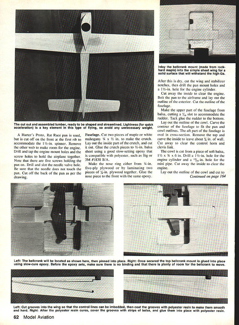
Construction usually starts with the hardware: landing gear, bellcrank, elevator control horn, fuel tank, and pan. The model uses a Harter's Proto Rat Race pan modified to fit the engine and spinner. Seal and glass the structure with polyester resin and two-ounce fiberglass as described below.
Hardware
- Landing gear:
- May be made from angle extrusion of hard aluminum alloy 3/32" thick or bent from sheet material.
- Drill holes per drawing dimensions.
- Axle: machined from 1/4"-dia. steel bar.
- Bellcrank:
- Cut from 1/16"-thick steel sheet.
- Hookup buttons and pulleys: machined from 1/4"-in. steel bar.
- Buttons extend through the bellcrank and are silver-soldered on the bottom.
- Elevator control horn:
- Made from same material as the bellcrank and silver-soldered to a piece of 1/16"-dia. piano wire.
- Fuel tank:
- Made from .010" tinplate (from a fuel can or K&S).
- Fuel pickup line is soldered to the outside of the tank, then drilled through from the inside.
Pan
- Use a Harter's Proto Rat Race pan.
- Cut off the front at the first rib to accommodate a 1-1/2" spinner.
- Remove the other webbing to make room for the engine.
- Drill and tap engine-mount holes and screw holes to hold the airplane together (note: five screws hold the pan).
- Drill and slot the needle-valve hole; ensure the needle does not touch the pan.
- Cut off the back of the pan per the drawing.
Fuselage
- Crutch:
- Cut two pieces of maple or white mahogany, 1/4" x 1/2", to make the crutch.
- Lay out and cut the inside part of the crutch.
- Glue the crutch pieces to 1/16" balsa sheet (or 1/8" where noted) using a good slow-setting epoxy compatible with polyester (e.g., Sig or 3M #1838 B/A).
- Nose ring:
- Make from 1/8" five-ply plywood or laminate two pieces of 1/16" plywood.
- Glue to the front with epoxy.
- After drying:
- Cut wing and stabilizer notches.
- Drill pan-mount holes and a 1" hole for the engine cylinder.
- Cut away inside clearance for the engine.
- Bolt the pan to the airframe, lay out and cut the exterior fuselage outline.
- Upper fuselage and cowl:
- Make the upper fuselage from balsa, cutting a 5/16" (or 3/16" in alternate text — use 5/16" per earlier layout) slot to accommodate the rudder and tack-glue rudder bottom.
- Carve the fuselage contour to fit the pan; aft fuselage is an oval cross section.
- Remove the top and carve inside, leaving about a 1/8" wall.
- Cut clearance for the control horn and clevis link.
- Cowl: cut from soft balsa; drill a 1" hole for the engine cylinder and a 5/8" hole for the mini pipe. Cut and clear engine space.
Shape and Bonding
- Laminate 1/4" plywood to the outside using a gap-filling cyanoacrylate (Hot Stuff CA) and accelerator:
- Spray balsa with accelerator, spread adhesive on plywood, press on balsa — bonding is nearly instant.
- Cowl base: piece of 1/2" balsa extending from the front of the cowl to the wing leading edge.
Wing
- Use 3/8" balsa for the wing.
- Taper the bottom to 3/16" thickness at the tips, leaving a flat portion to mate with the cowl.
- Cut the wing outline.
- Cut a .020" x 3/16" deep groove at the leading and trailing edges, parallel with and 3/32" from the bottom.
- Fill these slots with 1/64"-thick plywood and glue with thin CA to give a hard line for shaping the airfoil.
- Bellcrank mount:
- Cut from hard maple (do not glue to the bellcrank yet).
- Cut the wing to accept the bellcrank mount and to clear the bellcrank.
- Control-line grooves:
- Cut grooves in the bottom of the wing for the lines and caps to cover them.
- Seal the grooves with polyester resin.
- Tip guide: made from a piece of 3/64" brass tube, flattened to 3/32" inside dimension using short pieces of 3/64" wire. Both lines go through one tube. Glue in place with slow-setting epoxy.
- Airfoil:
- Shape with a lifting section in the center and symmetrical tips.
- Finish:
- Glue the bellcrank mount in place (ensure bellcrank and pivot pin can be removed to install pushrod).
- Leave the wing flat where it joins the fuselage and cowl.
- Cover the wing with two-ounce fiberglass and polyester resin.
- Drill the bellcrank mount pieces 1/8" for the bellcrank pivot; glue the mount pieces together with slow-setting epoxy with the bellcrank in place.
Stabilizer and Elevator
- Use 3/16" balsa sheet for the stabilizer.
- Cut the stabilizer outline.
- Cut a .020" x 3/8" deep groove in the leading and trailing edges and in the center of the 1/16" thickness; fill slots with 1/8" plywood and glue.
- Shape a symmetrical airfoil, leaving the center flat where it joins the fuselage.
- Cut the elevator from the stabilizer.
- Drill 1/16" and 5/32" holes for the control horn and end hinge-pin.
- Groove the elevator so the control horn wire and hinge-pin wire fit flush; glue with slow-setting epoxy.
- Cover stabilizer and elevator with two-ounce fiberglass and polyester resin, wrapping the glass around the elevator.
- Cut pockets in the stabilizer to accept the control horn wire and hinge-pin wire; wax the wires with paste wax, place them in pockets, fill with slow-setting epoxy to form hinges. When set, file or sand epoxy flush and cover with small fiberglass patches.
Assembly
- Seal all inside areas with polyester resin before final assembly.
- Pushrod:
- Make from 1/16" music wire.
- Rudder and tail-skid:
- Make mounts from 1/16" plywood; glue in place with slow-setting epoxy.
- Bellcrank and pushrod:
- Install the pushrod in the bellcrank and replace the pivot pin.
- Cover the ends of the pivot pin with two-ounce fiberglass and slow-setting epoxy to retain the pin.
- Wing and stabilizer:
- Use a solder "quick link" to establish elevator neutral while fitting into fuselage notches.
- Glue wing and stabilizer in place with slow-setting epoxy, maintaining zero incidence between them.
- Pan and engine:
- Glue the rear pan mount into the back of the fuselage.
- Disassemble the engine and mount the crankcase in the pan; wax the pan so final-glue won't stick to it.
- Wrap three layers of masking tape around the crankcase fins as needed.
- Bolt the fuselage to the pan after drilling mount holes through the wing.
- Cowl and hold-down:
- Glue the cowl in place.
- Glue a piece of 3/32" aluminum in the upper fuselage to act as a rear hold-down; drill and tap in line with pan holes for a 4-40 screw.
- Final shaping:
- Finish shaping and sanding the fuselage smooth.
- File the notches near the break at the pan with a small round file; do not file more than 1/16" deep.
- Fill the notches with strands of fiberglass and polyester resin; file and sand smooth.
- Fuel tank installation:
- Install the tank in the pan using silicone rubber (RTV).
- Notch the fuselage to clear the fuel-filling tubes.
- Seal the entire fuselage with polyester resin and sand smooth.
- Cover all seams and fillets with two-ounce fiberglass and polyester resin; sand smooth.
- Controls:
- Drill the air-supply hole through the cowl and install the throttle arm and throttle-arm shaft.
- A sewing-machine needle makes a good fuel pickup tube; ensure the needle does not project into the tank.
- Mount the bellcrank and check full movement of elevator and rudder.
- Install pushrod clevis and set control throws to approximately 1/4" up and down for elevator and 1/4" each way for the rudder.
- Final:
- Mount the engine and balance the model; finished weight should be about 22 oz.
Flying
- Balance the model about 3/8" aft of the wing leading edge.
- For first flights:
- Use about 18% nitro in the fuel, rich mixture.
- Trim for gentle climbs and turns.
- Run the engine in and gradually lean the mixture for best performance.
- Use a 60-ft. line and the starting procedure given in the rule book.
The Pink Lady has proven fast and competitive in club races. Its inverted appearance and simple construction make it a good choice for newcomers to Class B racing.
Plans and details are available from the author.
Transcribed from original scans by AI. Minor OCR errors may remain.

