
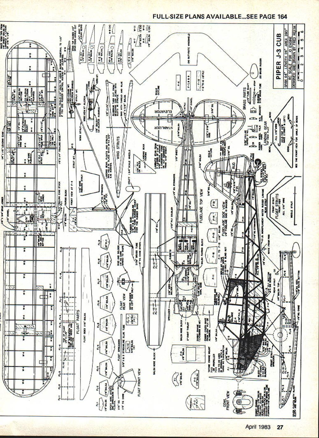
Piper J-3 Cub
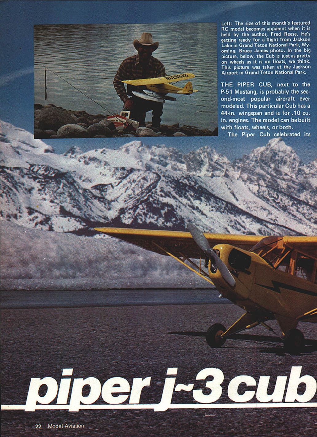
The Piper Cub, next to the P-51 Mustang, is probably the second-most popular aircraft ever modeled. This RC version has a 44-in. wingspan and is sized for .09–.10 cu. in. engines. The model can be built with floats, wheels, or both.
Who can ignore the charm and simple beauty of the Piper J-3 Cub? This model was built for 4-channel controls (and floats, if you like), but it also will fly well with a strong .049 and a lightweight 2-channel radio system.
Quick facts
- Scale: 1/4 (span 44 in, wing area 280 sq in)
- Recommended power: .09–.10 engines (or TD .049 for a lighter setup)
- Typical weight: about 33 oz with floats (about 25 oz without floats)
- Radio/battery: example given used a 4-ch radio with a 225 mAh pack (radio + pack = 11 oz)
History
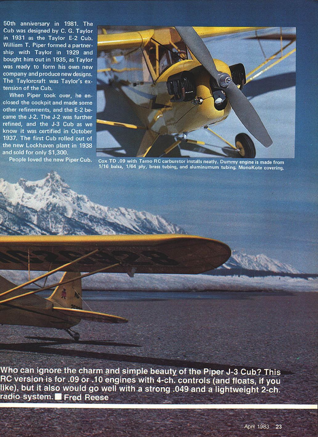
The Cub was designed by C. G. Taylor in 1931 as the Taylor E-2 Cub. William T. Piper formed a partnership with Taylor in 1929 and later bought him out in 1935 as Taylor prepared to form his own company and new designs (Taylorcraft being Taylor's extension of the Cub).
When Piper took over he enclosed the cockpit and made refinements; the E-2 became the J-2. The J-2 was further refined and the J-3 Cub was certified in October 1937. The first Cub rolled out of the Lock Haven plant in 1938 and sold for only $1,300. Flying schools quickly accepted the Cub; its easy-flying ability had new pilots soloing after less than three hours of instruction and the market boomed.
Production highlights:
- Over 8,000 Cubs sold in the three years after certification
- During World War II Piper built another ~6,000 as L-4 military aircraft
- After the war another ~720 Cubs were built before demand fell
- The Super Cub (PA-18) remained in production and later variations reintroduced Continental, Franklin, Lycoming, and Lenape engines, and floats (Edo twin floats)
The J3L-65 Cub modeled here is shown in Vol. 7, U.S. Civil Aircraft, Juptner.
Model overview and notes
- The author (Fred Reese) originally intended to scale all outlines exactly, but the model was not stable enough, so the tail surfaces were enlarged while retaining scale shape.
- Weight is critical: about 33 oz with floats is the practical maximum for good performance. A lighter radio system (micro-type) could reduce weight by ~4 oz and greatly improve performance.
- Floats add fun and challenge; conversion between landplane and floats is quick (a few minutes).
- Ideal prop for the Cox TD .09 is the old Cox 7 x 3½. A 7 x 4 is a little too much and should be cut to about 6½ in and rebalanced, or use a 7 x 3.
Design and installation highlights:
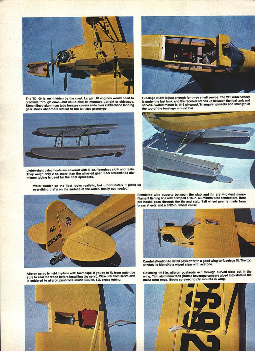
- The TD .09 is well-hidden by the cowl; larger .10 engines may protrude through the cowl or be mounted upright/sideways.
- Streamlined aluminum-tube bungee covers slide over rubber-band landing-gear shock absorbers similar to the full-size prototype.
- Fuselage width accommodates three small servos. The 225 mAh battery fits under the fuel tank; the receiver stands upright between the tank and servos. Switch mount is 1/16 plywood.
- Triangular gussets add strength at the top of the fuselage around bulkhead F-4.
- Lightweight balsa floats are covered with 3/4-oz fiberglass cloth and resin and weigh only about 2 oz more than wheeled gear. K&S streamlined aluminum tubing is used for the float spreaders.
- A water rudder on the float looks realistic but tends to pick up debris and is often unnecessary.
- Simulated wire supports between the stabilizer and fin use 4-lb test monofilament fishing line crimped into 1/16-in aluminum-tube connectors. Bent-pin hooks pass through the fin and stab.
- Tail-wheel gear is made from brass sheet with a 3/32-in wheel collar.
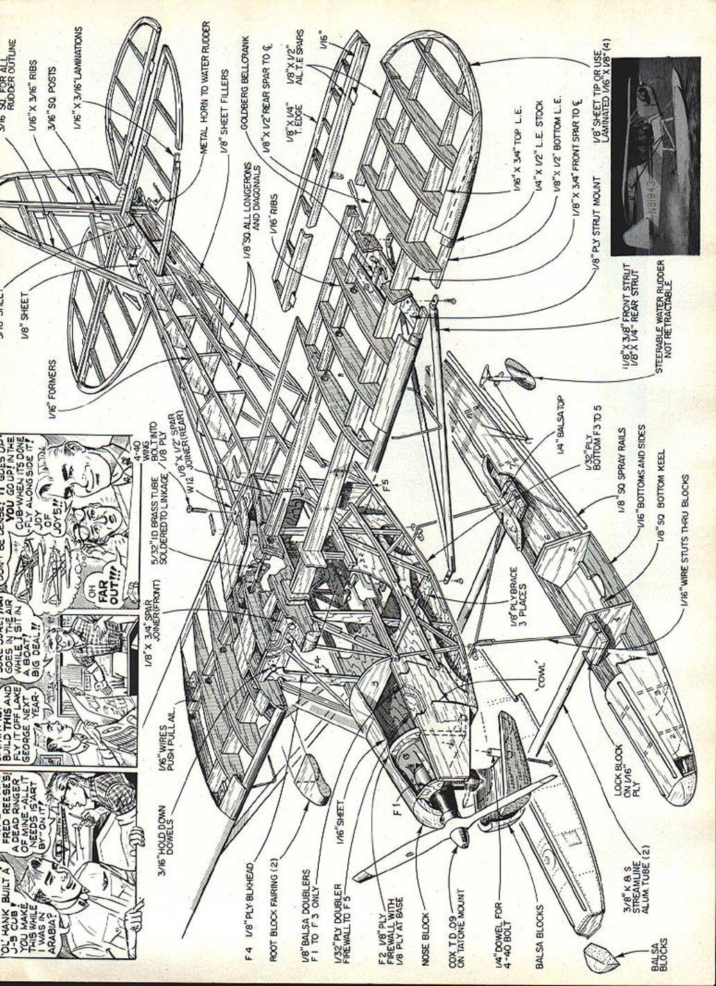
Fuselage construction
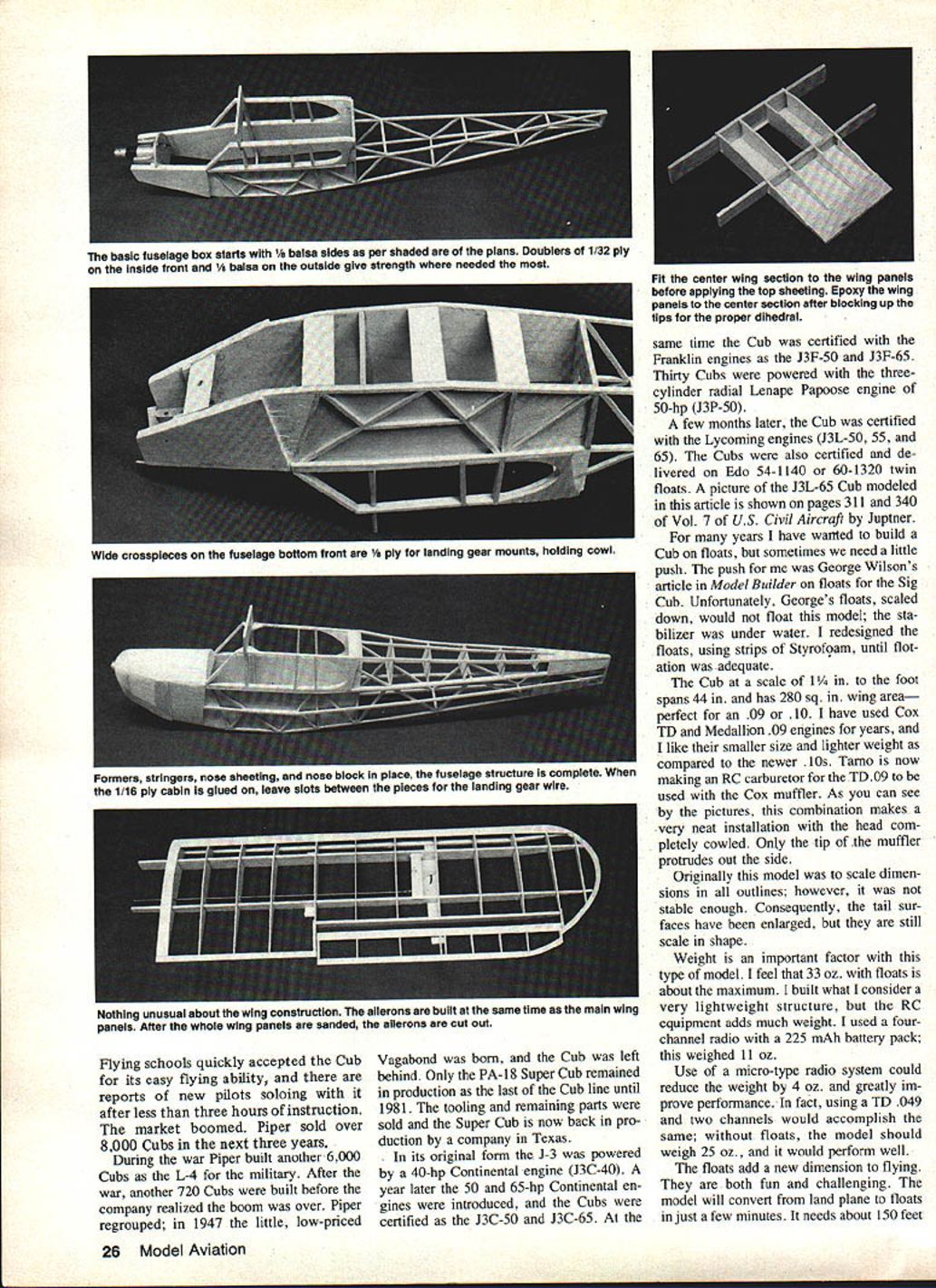
- Using the shaded guide on the plan, build two fuselage sides from 1/8" sq. balsa and 1/4" sheet balsa. Glue 1/32" ply doublers to the inside of the cabin area and 1/8" balsa nose doublers over the outside from the nose to the windshield.
- Join the fuselage sides with bulkheads F-4 and F-5. Glue the tail together and add the 1/4" sq. crosspieces.
- Mount the engine and epoxy in the firewall. Glue in the 1/8" ply cowl and landing gear mounts (F-6, F-7, F-8, F-9).
- Glue on the 1/16" ply cabin floor pieces, leaving 1/16" slots between pieces for the 1/16" wire landing gear. Add 1/8" balsa doublers around the window areas, overlapping the joints.
- Glue on the two 1/8" sq. side stringers; the top one is glued right over the fuselage side. Add 1/8" balsa triangular gussets at the top of the cabin frame and bulkhead F-4.
- Glue in bulkheads F-1 and F-3, and add the top 1/16" sheeting. Trim the front of the 1/16" sheeting and glue on the front cowl block.
- Glue 1" strips of 1/16" balsa to the sides of the cowl to define the rear cowl edge (most of this sheet will be sanded away during shaping). Sand the bottom of the engine compartment true with a flat sanding block.
- Removable cowl hold-down: epoxy a 4-40 blind nut in a 1/8" hole centered in F-6. Drill a 1/8" hole down the center of a 1/4" dowel, cut a 9/16" length, run a 3/4" 4-40 bolt through the dowel into the blind nut and tighten. Drill a 1/4" hole in the cowl block for the dowel and epoxy the dowel into the cowl block while holding it tight to the fuselage. Trim the back of the cowl block to line up with the cowl edge and glue on 3/16" balsa wedges behind the cowl to form an engine cooling air duct. Shape the outside of the cowl and hollow the inside to clear the engine.
- Glue on bulkheads F-11 through F-15 and the two top side stringers. Glue in 1/8" balsa between the top stringers for the rudder and stab mounts; slot the side sheets later for the stab. Glue pieces of 1/8" sheet between the side stringers for pushrod exits. Add the top center 1/8" sq. stringer.
- Glue in F-10 and sand the fuselage to final shape. Flat-sand the 1/8" doublers around the windows to match the cross section of F-4.
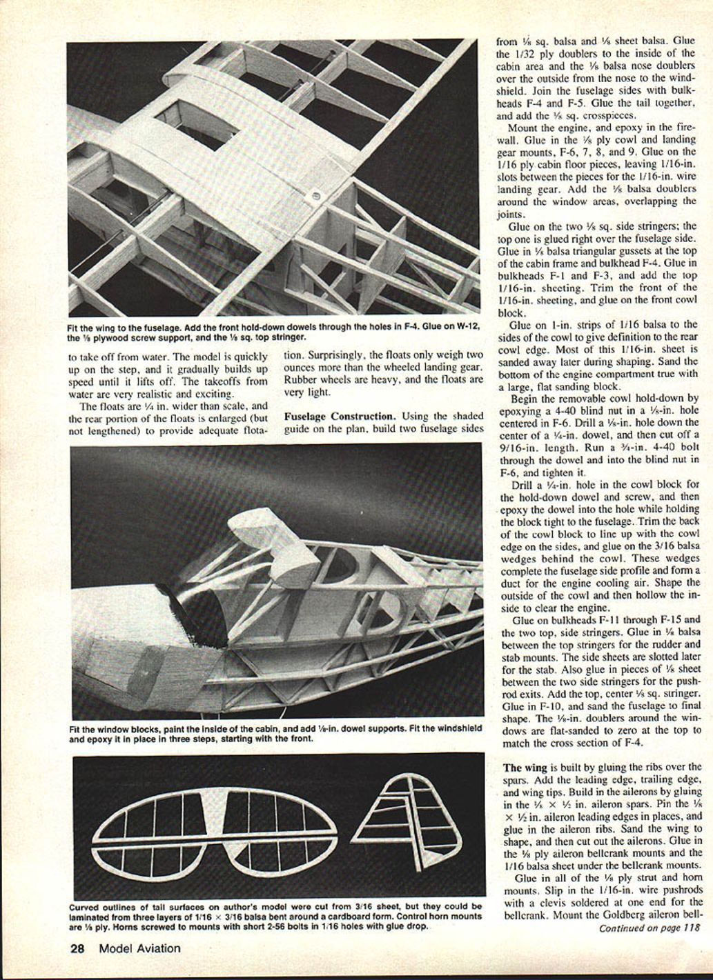
Windshield:
- Cut the windshield from clear butyrate (pattern on the plan). Fit and epoxy in place in three steps, starting with the front.
Sealing:
- Give the entire structure a coat of Balsarite to seal the wood before final covering.
Wing construction
- Build the wing by gluing the ribs over the spars. Add the leading edge, trailing edge, and wingtips.
- Build the ailerons by gluing in the 1/8" x 1/8" aileron spars. Pin the 1/8" x 1/4" aileron leading edges in place and glue in the aileron ribs. Sand the wing to shape, then cut out the ailerons.
- Glue in 1/8" ply aileron bellcrank mounts and 1/16" balsa sheet under the bellcrank mounts. Glue in all 1/8" ply strut and horn mounts.
- Slip in the 1/16" wire pushrods with a clevis soldered at one end for the bellcrank. Mount the Goldberg aileron bellcrank.
- For the curved pushrod exit: drill down through the outer hole in the bellcrank with a 1/16" drill through the balsa bottom; with the drill running, rotate the bellcrank gently to cut a curved slot for the pushrod exit.
- Build the wing center section by stacking ribs and spar joiners on the 1/16" balsa bottom. Trial-fit the panels into the center section. When everything fits easily, glue the top 1/16" sheeting to the center section.
- Epoxy the wing panels to the center section, blocking up each wingtip 1/2" (use 1/2" under each tip if you don't use ailerons). Sand off the bottom edges of the spar joiners even with the spars.
Wing-to-fuselage fit and hold-down:
- Fit the wing to the fuselage. Drill two 1/8" holes into the wing through F-4 and glue 1/2" lengths of 1/8" dowel into the holes, leaving 1/8" protruding for the front hold-down. Glue on W-12 (a 1/8" ply screw support) and the 1/8" sq. top stringer. Drill and install a #4 sheet-metal screw to hold the wing in place.
- Glue a piece of 1/8" balsa over the top front of F-4 to cover the dowel holes. Glue on two balsa fairing blocks and sand to shape.
Tail surfaces
- Make tail outlines from 3/16" sheet, or laminate outlines with three layers of 1/16" x 3/16" balsa soaked in hot water, wrapped around a form, with white glue between layers.
- Add 1/16" x 3/16" ribs. Join elevator halves with a length of 1/8" dowel and glue in 1/8" ply horn mounts. Sand edges round, cover stabilizer and elevator, and install hinges.
- Cut a slot in the fuselage for the stabilizer. Trim away covering in the center of the stabilizer even with the fuselage sides and glue the stabilizer in place.
Floats construction
- Floats are built with 1/4" x 2" balsa tops with 1/16" balsa bulkheads, sides and bottom. Lay the 1/4" x 2" x 18" tops over the plan, mark bulkhead locations, and draw a center line.
- Glue bulkheads in place and add a 1/8" sq. keel. Glue in FL-10s and FL-11s to make boxed slots for the aluminum spreader tubes.
- Glue on float sides and bottom, glue on nose blocks, and sand to shape.
- Cover floats with 3/4-oz. fiberglass cloth and resin. Use toilet paper to blot away excess resin; if resin is too thick, add a little acetone to thin. When dry, sand lightly and glue on 1/8" sq. balsa chines and 1/16" sq. top rails. Prime and paint the floats silver.
- Cut slots for the spreaders and join floats and spreaders with epoxy. Mount 1/16" wire float struts to the fuselage and epoxy the wires into holes drilled in the floats. Solder the middle strut to the front strut at the top.
- Floats are 1/4" wider than scale and the rear portion is enlarged (not lengthened) to provide adequate flotation. They weigh only about 2 oz more than the wheeled gear.
Note on steerable water rudder:
- A steerable float rudder driven by 4-lb monofilament works but tends to pick up weeds and algae during takeoff runs; the author found it unnecessary and often removable.
Landing gear
Tail wheel:
- Tail wheel unit made from thin sheet brass and a 3/32" wheel collar tapped for a 4-40 bolt. Wheel yoke and horn are soldered to the wheel collar. The completed assembly is attached to the brass arm with a 1/4" 4-40 bolt.
- The tail wheel is screwed on tight (locked) to prevent ground-looping; full-size Cubs use locked tail wheels for takeoff.
- Connect the rudder horn to the wheel horn with electric motor brush springs to allow rudder movement even with tail wheel locked.
Main gear:
- Main landing gear is made from 1/16" piano wire. Bend carefully, adjust until it sits flat on a table, then screw to the fuselage before soldering. Bind junctions with fine copper wire and solder.
- Solder 3/32" brass tubes over the axles. Use lightweight wheels (example: Kraft 1/4" wheels), sand hubs and paint yellow with a 1/8" black edge; the word "Cub" can be hand-painted in the hub centers.
- Cut two 1" lengths of 3/8" K&S streamlined aluminum tube covered with yellow trim for the bungee covers. Wrap landing gear hooks with rubber bands to hold the bungee covers in place.
Radio, power, and waterproofing
- Fuselage width is just enough for three small servos. Aileron servo can be held in place with foam tape; seal the wood before installing if flying from water.
- 225 mAh battery pack under the fuel tank; receiver stands up between tank and servos. Switch mount is 1/16" plywood.
- Use of a micro-type radio system could reduce weight by ~4 oz and greatly improve performance. Using a TD .049 engine and two channels would also give a satisfactory, lighter setup.
- If you fly from water, protect your radio; the Cub is small and does not lend itself to a waterproof compartment. Follow waterproofing directions (see George Myers, "Radio Technique," Model Aviation, Feb 1982).
Prop recommendations:
- Best for Cox TD .09: Cox 7 x 3½ (if unavailable, modify a 7 x 4 down to about 6½ and rebalance, or use a 7 x 3).
Covering and finish
- Give the entire structure a coat of Balsarite to seal the wood.
- Cover with Yellow MonoKote or EconoKote. Use matching yellow MonoKote trim over the window areas and edges of the iron-on covering; iron only to the edge of the windows to avoid melting them.
- Use black MonoKote trim for the side stripe and numbers. The small Cub logo on the rudder was hand-painted using Pactra Namel for plastic models.
- Paint inside cabin yellow and area over instrument panel flat black. Add 1/8" dowel cabin supports (painted yellow).
Flying notes
- The model gets up on the step and gradually builds speed until it lifts off; takeoffs from water are realistic and exciting.
- Aileron response on a slow-flying high-wing airplane can be sluggish; flying the Cub a bit faster keeps control response normal.
- Don't rush it off the water; it will take off when ready.
- The floats add a new dimension to flying—fun and challenging. They are easily removed if you prefer land operations.
Enjoy your Cub. There is always something special about a Piper Cub, no matter how large or small it is.
Transcribed from original scans by AI. Minor OCR errors may remain.

