
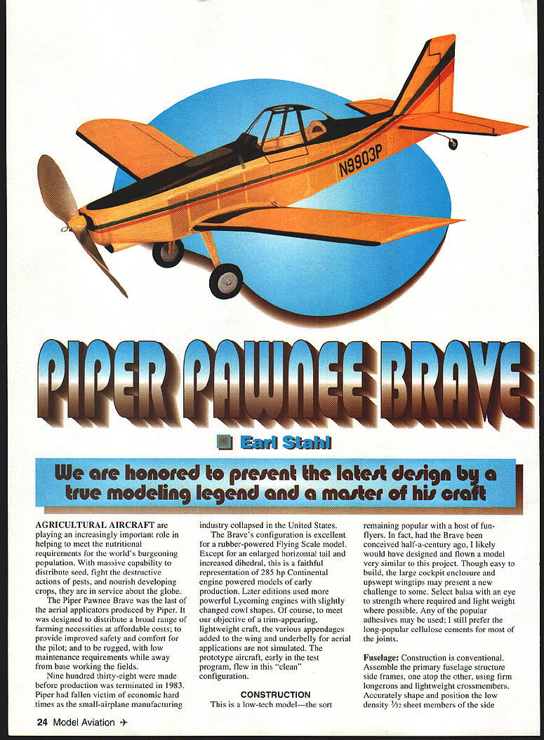
Piper Pawnee Brave
Earl Stahl
We are honored to present the latest design by a true modeling legend and a master of his craft.
Agricultural aircraft are playing an increasingly important role in helping to meet the nutritional requirements of the world's burgeoning population. With massive capability to distribute seed, fight destructive pests, and nourish developing crops, they are in service worldwide.
The Piper Pawnee Brave was the last of the aerial applicators produced by Piper. It was designed to distribute a broad range of farm inputs affordably, to provide improved safety and comfort for the pilot, and to be rugged with low maintenance requirements while working away from base. Nine hundred thirty-eight were built before production was terminated in 1983, when Piper fell victim to the economic hard times that collapsed the small-airplane manufacturing industry in the United States.
The Brave's configuration is excellent for a rubber-powered Flying Scale model. Except for an enlarged horizontal tail and increased dihedral, this model is a faithful representation of the early-production versions powered by a 285-hp Continental engine. Later editions used more powerful Lycoming engines with slightly different cowl shapes. To meet our objective of a trim-appearing, lightweight craft, the various appendages added to the wing and underbelly for aerial application are not simulated. The prototype aircraft, early in the test program, flew in this "clean" configuration.
Construction
This is a low-tech model—the sort remaining popular with a host of fun-flyers. In fact, had the Brave been conceived half a century ago, I likely would have designed and flown a model very similar to this project. Though easy to build, the large cockpit enclosure and upswept wingtips may present a new challenge to some. Select balsa with an eye to strength where required and light weight where possible. Any popular adhesive may be used; I still prefer the long-popular cellulose cements for most of the joints.
Fuselage
Construction is conventional. Assemble the primary fuselage side frames, one atop the other, using firm longerons and lightweight crossmembers. Accurately shape and position the low-density 1/32" sheet members of the side fuselage. When the fuselage and wing mate, establish the desired wing incidence angle.
Place the two side frames, inverted, over the aft top-view station F-7 (tail post) after first cracking the top and bottom longerons. The F-3 and F-8 sides will conform to the angular contour of the airplane's body. Firmly glue the cracked longerons to reestablish structural integrity. Once the basic frame is complete, glue the fuselage formers in place and add stringers.
Use a long straight spline and fine sandpaper on the glued faces to touch up irregularities in shape, positioning the formers before gluing the low-density 1/32" sheet upper forward fuselage and nose in several narrow pieces. Care should be taken to cover the contoured lower nose with 1/32" material. Others may find it preferable to fill the section with thicker sheet or with popular blue foam.
Notice the triangular 1/16" sheet horizontal tail mounts on the rear fuselage. Cut and position right and left with care, since these will establish the incidence angle of the tail when later glued in place. Four pieces of 1/8" sheet balsa glued together, cross-grained, are used to form the nose. Cut square holes to receive the removable nose plug as well as the simulated air intake and engine before joining the parts. Glue the nose block to the forward sides at station F-1. Carefully trim, sand, and dress the nose and adjacent sheet-covered areas to the configuration shown.
Specifications
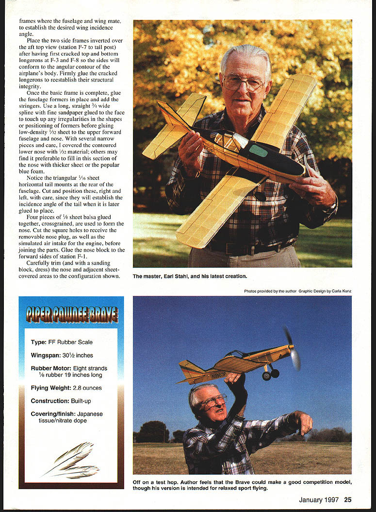
- Type: FF Rubber Scale
- Wingspan: 30.5 inches
- Rubber motor: Eight strands of 1/8" rubber, 19 inches long
- Flying weight: 2.8 ounces
- Construction: Built-up
- Covering/finish: Japanese tissue / nitrate dope
Transcribed from original scans by AI. Minor OCR errors may remain.

