
The Pitcairn Mailwing
Al Stott
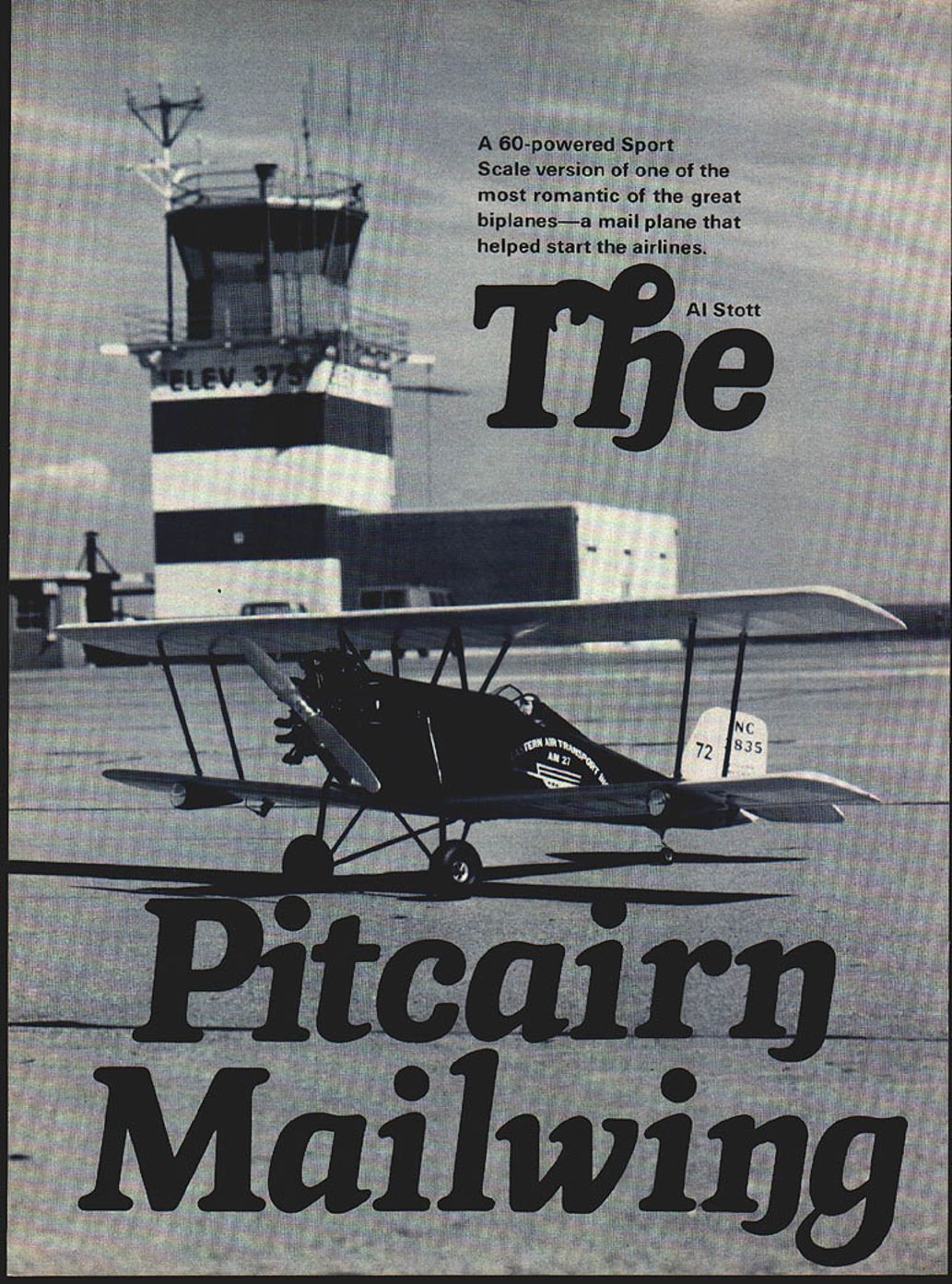
A .60‑powered Sport Scale version of one of the most romantic of the great biplanes — a mail plane that helped start the airlines.
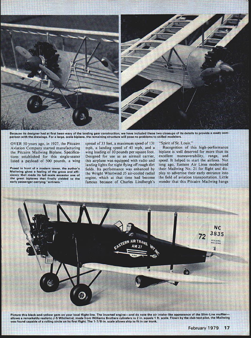
Over 50 years ago, in 1927, the Pitcairn Aviation Company started manufacturing the Pitcairn Mailwing biplane. Specifications established for this single‑seater listed a payload of 500 pounds, a wingspan of 33 feet, a maximum speed of 131 mph, a landing speed of 45 mph, and a wing loading of 10 pounds per square foot. Designed for use as an airmail carrier, this airplane was equipped with radio and landing lights for night flying off rough dirt fields. Its performance was enhanced by the Wright Whirlwind J5 air‑cooled radial engine, which at that time had become famous because of Charles Lindbergh's Spirit of St. Louis.
Recognition of this high‑performance biplane is well deserved for more than its excellent maneuverability, range, and speed. It helped to start the airlines. Not long ago, Eastern Air Lines modernized their Mailwing No. 21 for flight and display to advertise their early entrance into the field of aviation transportation. Little wonder that this Pitcairn Mailwing hangs from the ceiling of the new National Air and Space Museum at the Smithsonian in Washington, D.C. In other areas, visitors to the Shannon Airport Museum at Fredericksburg, Virginia, and to the Tallmantz Museum on the West Coast, have been able to view Pitcairn Mailwings on display.
History and Development
The Mailwing evolved from an earlier Pitcairn biplane, called Fleet Wing II (one should not confuse this aircraft with the "Fleet" biplane). Fleet Wing II biplanes were powered by OX‑5 water‑cooled engines housed in cowlings resembling those fitted on Waco and Travel Air biplanes. If one should choose to build an authentic looking Fleet Wing II model, plans of the Mailwing could be altered easily by eliminating the air‑cooled engine, substituting the extended OX‑5 type engine cowling, adding another seat, utilizing a simpler landing gear, and discarding the landing lights from the Mailwing plans.
Very important to the flying qualities of the Mailwing was the airfoil, which evolved from the combination of the desirable features of two previously used undercambered airfoils. One of these airfoils was of German origin and the other was of U.S. military heritage. Tests run in the N.A.C.A. wind tunnel at Langley Field, Virginia, proved the wisdom of the hybrid airfoil chosen. Demonstration flights made with a Pitcairn Mailwing at very low flying speeds drew many favorable comments from observing pilots.
The single‑seat Mailwing was designated the PA‑5. A companion biplane in a three‑place version was known as the Pitcairn Sport Mailwing. The color scheme used to paint the Pitcairn Mailwings was black on the fuselage (sometimes including the fin and rudder), and the remainder of the aircraft painted yellow. A bluish tint noted on some photographs is due to reflections.
James Triggs' drawings of this airplane were published in the January 1959 American Modeler and the Fall 1960 Air Progress. Although Triggs did an excellent overall job on the Mailwing, he omitted the front, short landing gear bracing struts that attached between the lower longerons and the oleo struts. A previously published small U‑control scale model of the Mailwing was also an excellent model designed from Triggs' drawings, but likewise omitted the same struts. This mistake was pointed out to me by the chief engineer of the Mailwing design office. A color photograph of the Mailwing at Shannon Airport in Virginia graced the cover of the May 1968 American Aircraft Modeler. This picture shows the missing struts and the color scheme of the subject aircraft.
The designers at Pitcairn wanted to make their landing gear rear strut braces attach at the same points on the lower longerons that also served to attach the front spar of the lower wing. To do so, they notched the leading edges next to the fuselage sides at an angle corresponding to the angle of the struts to provide access and clearance. It is possible that metal fairing plates were intended to be used to cover these notches. However, the PA‑5 at the Shannon Air Museum has open notches.
Design Features
The author utilized an unnotched one‑piece lower wing on this Sport Scale model because of the strength advantage of the sheet‑covered middle section of the leading edge of this wing. The aileron horns of the author's ship were installed under the ailerons and the hinges were attached at the top edges to provide long, adjustable moment arms. The true position of these horns is at the top at the locations noted on the drawing.
Another feature noticed on this PA‑5 was that the front corner of the cowling, just to the rear of the engine, was radiused with a concave instead of a convex radius. It is believed that this radius provided more clearance when the engine manifolds were installed.
Still another feature noted was the use of flat area, forward‑facing gusset plates in the weldments of the landing gear strut/axle junctions. Drag from these plates must have been quite large; only a great desire for strength would cause one to use this construction. Those dirt landing fields must really have been rough! The oleo struts were very soft in order to attenuate the transmission of large vibrational shock loads. Surprisingly, pilots who fly this PA‑5 for exhibition prefer to land on grass rather than on paved runways. The landing gear is tuned better to the grass surface than to the smooth runways, and the pilots find that the build‑up of rocking or sway on the paved runways can easily cause ground looping.
One interesting fact concerned the rigging of the wings. Wash‑out was set into the upper wingtips, as has been the case on many models, but this was considered in that day to be a company secret. Another innovation related to the ailerons, which were located only on the lower wing and were differential operating. Unlike differential ailerons used in models, the action was unique: the down‑moving aileron did not continue to move downward, but instead returned toward neutral after a short angular movement while the up‑moving aileron continued to move upward toward its maximum control position. Undoubtedly, this was a good way of eliminating unwanted drag and yaw.
Stability qualities of this aircraft were further assisted by the trimmable stabilizer, which adjusted over the range of 2° positive to 2° negative. While in the design stage, an attempt was made to offset engine torque by means of a side‑cambered rudder fin, but this idea was discarded.
Model Construction
Referring to the sport scale model drawings of the Pitcairn Mailwing PA‑5, a modeler will realize that a fair amount of model building experience is required to build it. Having that experience, the builder can readily work from the plans. Therefore, lengthy detailed construction directions have not been included in this article, except in special cases. Basically, the construction methods detailed in the drawings, and the general design parameters incorporated, have been proven on previous models, thereby assuring the strength and flyability of this model without increasing the tail areas or the moment arms.
Shannon Air Museum personnel informed the author that models PA‑6, PA‑7, and PA‑8 incorporated longer fuselages to improve ground handling. Had this information been available prior to this model design, it would have been worth considering for incorporation with appropriate model designation change. Such a model would have been several inches longer; most of the increase would have been in the length behind the cockpit and a little in front of the wing. All of which would be advantageous to a scale model.
In case anyone wonders why a scale of 1 3/4 inch = 1 foot was used for this scale model, the answer is simple. The design was made using an original factory print having a scale of 1/4 inch = 1 foot. Simple multiplication by 7 produced the scale used. Calculations for a model built to this scale indicated that a very acceptable wing area of almost 900 sq. in. would be obtained. A scale of 2 inches = 1 foot did not seem more desirable because per wing span would have been 66 inches. An increase of over 4 inches of the upper wing span would have made the assembled model airplane too large to be placed on the back seat of an automobile.
The author's decisions were largely a compromise based on a desire to fun‑fly even in moderately windy weather, and possibly to enter a contest not requiring exact scale. Although the model deviates from scale in the selection of airfoil and the slightly larger engine scale, the plans show the true outline except as previously noted.
For a realistic appearance, a slightly over‑size 2 inch = 1 foot Williams Wright Whirlwind J5 was installed in a way to largely conceal the inverted .60 engine. Further streamlining and camouflaging of the engine were accomplished by a fiberglass cowling to provide as much space around the engine as possible for the muffler, and to permit the installation of the battery pack under the cowling, if desired, to help establish the correct C.G. location without resorting to excess dead weight for balance.
It is common practice to remove scale‑like engines on routine test flights and, if necessary, to substitute an equivalent weight to prevent a shift of C.G. For this reason, the fiberglass cowl and engine crankcase were formed as separate molded parts.
Materials and Components (from plans)
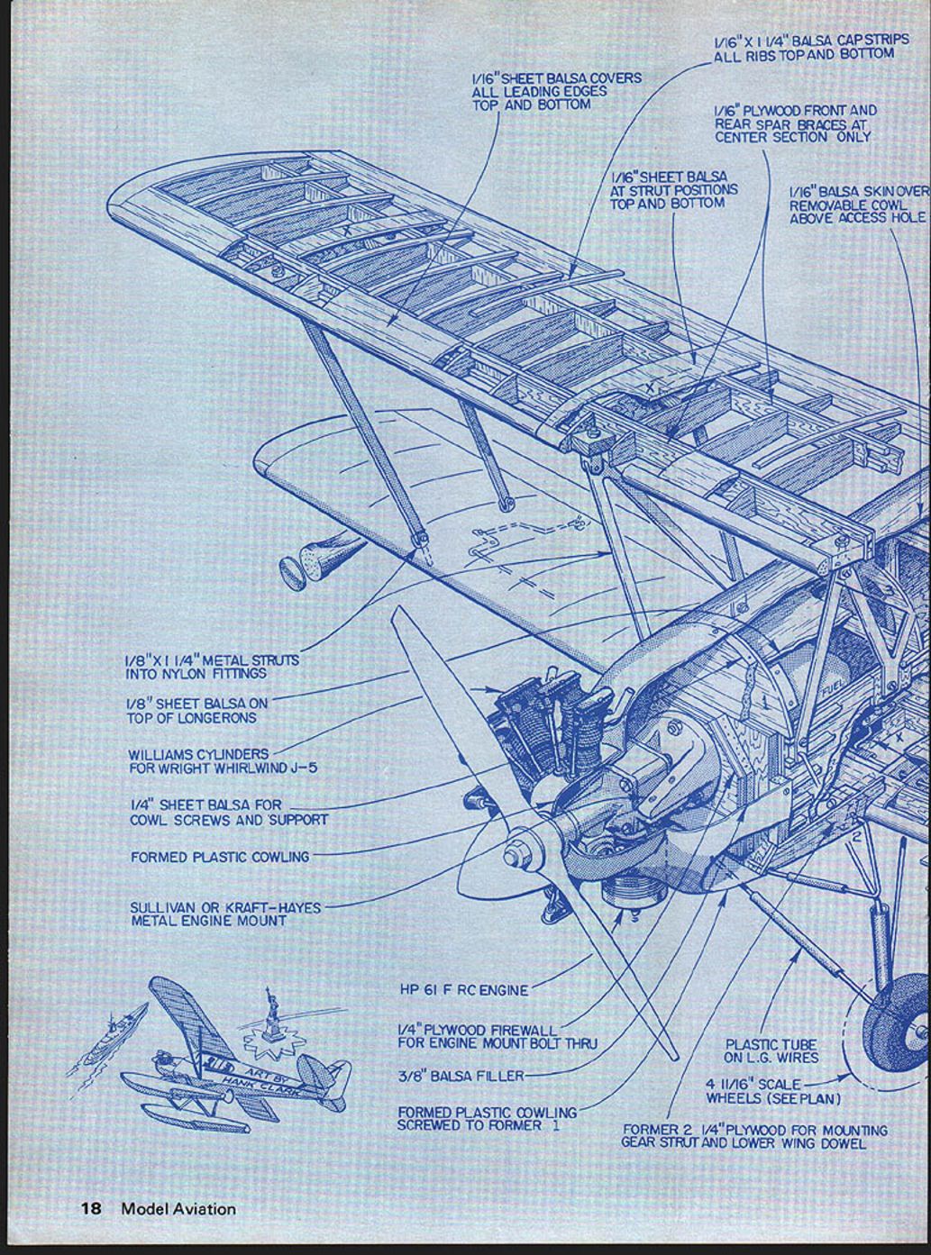
- 1/16" x 1 1/4" balsa cap strips — all ribs top and bottom
- 1/16" sheet balsa covers — all leading edges top and bottom
- 1/16" plywood front and rear spar braces at center section only
- 1/16" sheet balsa at strut positions — top and bottom
- 1/16" balsa skin over removable cowl above access hole
- 1/8" x 1/4" metal struts into nylon fittings
- 1/8" sheet balsa on top of longerons
- Williams cylinders for Wright Whirlwind J‑5
- 1/4" sheet balsa for cowl screws and support
- Formed plastic cowling
- Sullivan or Kraft‑Hayes metal engine mount
- .60 F R/C engine (example HP 61 listed)
- 1/4" plywood firewall for engine mount bolt‑thru
- 3/8" balsa filler
- Formed plastic cowling screwed to former 1
- Plastic tube on landing gear wires
- 4 11/16" scale wheels (see plan)
- Former 2, 1/4" plywood for mounting gear strut and lower wing dowel
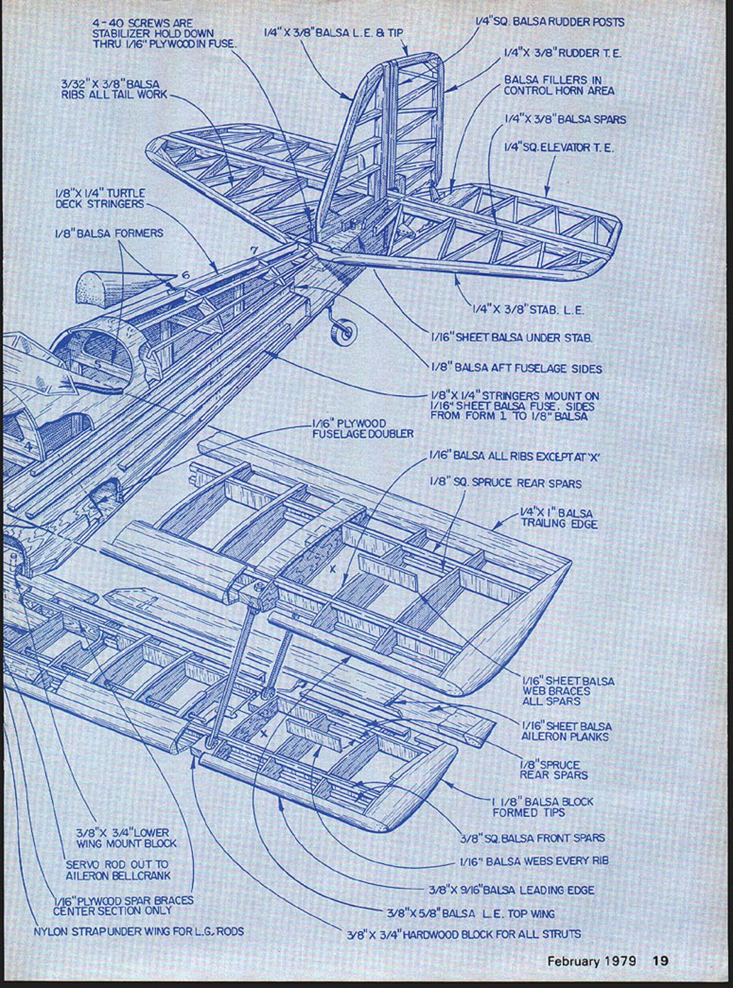
- 4‑40 screws are stabilizer hold down through 1/16" plywood in fuse
- 1/4" x 3/8" balsa leading edge & tip
- 1/4" sq balsa rudder posts
- 1/4" x 3/8" rudder trailing edge
- 3/32" x 3/8" balsa ribs — all tailwork
- Balsa fillers in control horn area
- 1/4" x 3/8" balsa spars
- 1/4" sq elevator trailing edge
- 1/4" x 3/8" stabilizer leading edge
- 1/16" sheet balsa under stab
- 1/8" x 1/4" turtle deck stringers
- 1/8" balsa formers
- 1/16" plywood fuselage doubler
- 1/8" balsa aft fuselage sides
- 1/8" x 1/4" stringers mount on 1/16" sheet balsa fuse, sides from form 1 to 1/8" balsa
- 1/16" balsa all ribs except at "X"
- 1/8" sq spruce rear spars
- 1/4" x 1" balsa trailing edge
- 1/16" sheet balsa aileron planks
- 1/8" spruce rear spars
- 1/8" balsa block formed tips
- 3/8" sq balsa front spars
- 1/16" balsa webs every rib
- 3/8" x 9/16" balsa leading edge
- 3/8" x 5/8" balsa leading edge top wing
- 3/8" x 3/4" hardwood block for all struts
- 3/8" x 3/4" lower wing mount block
- Servo rod out to aileron bellcrank
- 1/16" plywood spar braces center section only
- Nylon strap under wing for landing gear rods
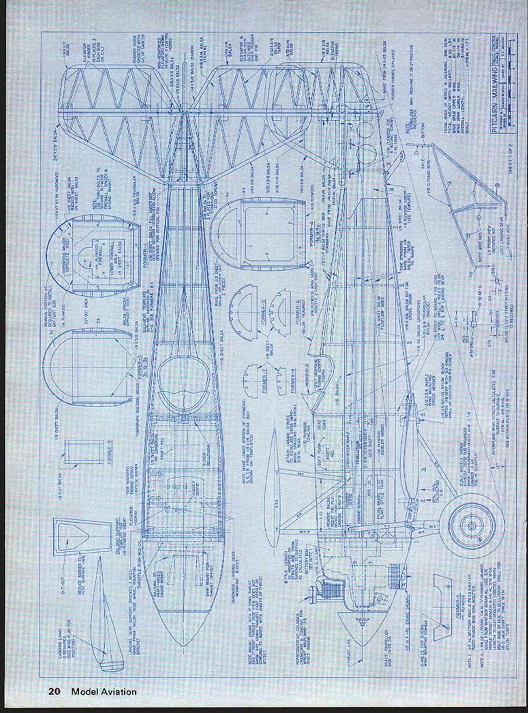
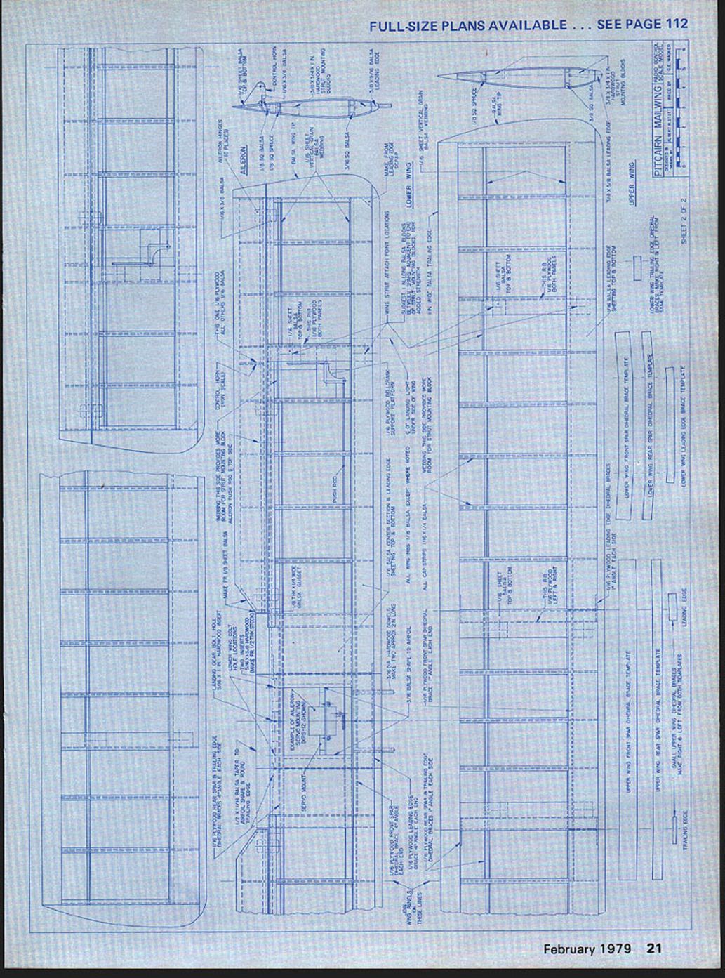
PITCAIRN MAILWING — SHEET 1 OF 2 PITCAIRN MAILWING — SHEET 2 OF 2
Lower wing — Upper wing
Fiberglass Crankcase and Cowling Method
The crankcase form was made of hard balsa previously used for packing or crating because of its weight. This balsa was cut into discs and laminated before shaping to size. During machining it was observed that the form tended to turn out of round even in a lathe. This was due to the end grain not cutting the same as the other grain directions. Care had to be taken to bring the form back to round by hand work.
Finally, the form was fitted with a 1/2‑in. diameter wood‑holding dowel centrally located to extend axially out of the back. This dowel can be supported easily by a vise while applying the fiberglass. No attempt was made to provide draft or taper on the form diameters since it was believed that the fiberglass crankcase would have to be cut from the form anyway. Then there was a pleasant surprise: when the easy‑does‑it method was completed, the fiberglass crankcase was removed in one piece without damage to either the crankcase or the form.
The method of removal is as follows:
- Remove the thumb tacks which held the Saran Wrap and glass cloth in place while being coated with HobbyPoxy II, and during the placement of a balloon to cover the lay‑up.
- Trim fiberglass at the rear outer diameter to assure that no fiberglass locks around the back corner of the form. Then, rough out the front open hole of the fiberglass cowl, removing any excess that was not cut away to extract thumb tacks. These operations are easier when the fiberglass has cured two or three hours but has not completely hardened.
- Insert an artist's flexible palette knife from the rear of the form under the fiberglass and Saran Wrap. (The Japanese artist paint mixing knife used by the author proved ideal.)
- Slide the knife axially along the surface and work 360° around the form — the same way cooks remove cakes from layer‑cake pans. This will free the fiberglass from the form. Some slight temporary stretching may occur and the Saran Wrap may be displaced partially. Repeat this process until the fiberglass crankcase can be pulled from the form.
The author had a 3‑in. flexible blade that tapered in thickness from .014 inch at the tip to .028 inch at the handle. Also, the sides of the knife were slightly tapered and the tip was bent upward an almost imperceptible amount.
Three layers of glass cloth with good coatings of HobbyPoxy II will make a light crankcase, but five layers of glass cloth starting with medium weight and finishing with light weight glass cloth would be better. Smoother and thinner coatings of epoxy can be applied when the epoxy is kept warm during application by means of a small hair dryer. Bubbles can be excluded by careful application under these warm conditions, but do not worry about bubbles — since any that mar the surface can be opened and filled later so as not to show when painted.
Care should be taken to prevent round‑off of the flats on the crankcase provided for the mounting of the engine cylinders. This can be accomplished by taping a layer of foam rubber over the deflated balloon to press evenly, completely around the section having the flats, while the epoxy hardens. Do not use rubber bands to retain the foam rubber, because they will localize the pressure too much and permanently indent the fiberglass. Masking tape works well to hold the foam rubber in place.
The engine cowling form was made using layers of scrap plastic foam with shaped 1/4" balsa sheets laminated front and back to serve as templates and to prevent distortion or rounding of the front and back corners while under pressure. A holding dowel was built into this form. After the form was shaped to size, the author used U.S. Gypsum Top Coat mixed with water to fill the pores of the plastic foam and to blend the shape of the form. When almost dry and hard, the form was completely sanded.
Top Coat is not easily sanded when very rough and fully hardened, but it is possible to sand more easily when a very slight amount of moisture still remains just prior to final hardening. Top Coat can do a better job at less expense when compared to the use of a filler coating made with Tite Bond cement. Used on the plastic foam surface, this strong coating insulates and protects the plastic foam from damage when hot air is used to soften and smooth the epoxy. The coating need not be very thick, and thinner applications are preferred to reduce the number of coatings that have to be applied to take care of shrinkage that can occur in thick sections. Waxing of this form is not recommended since Saran Wrap can be applied easily and shrunk very neatly on the form. After the fiberglass work was completed, the flexible palette knife was used as previously explained to help remove the cowling without damage to either the cowling or the form.
The author tried without success to locally procure balloons large enough for the easy‑does‑it method of making this engine cowling; even Jumbo‑size and 16‑in. diameter balloons were not quite big enough. Therefore, a more than usual amount of sanding was necessary for a smooth finish. One word of caution when attempting to use the easy‑does‑it method: secure the glass cloth well with thumb tacks in areas to be cut away to prevent shifting due to balloon breakage or slippage. Balloons that are a little too small may go onto the form but slip back off again — especially when your back is turned. In so doing, the position of the loose fiberglass cloth will be shifted. Following the rule of thumb that the balloon be at least twice as big as the form usually helps to prevent trouble, but the sloping shape of the engine cowling encouraged slippage of the balloons.
One glance at the landing gear may tend to make the potential builder have second thoughts. The author confesses that this item did delay the start of the project. Happily, the landing gear came out right the first time, with very little extra effort, using only four single pieces of 1/8" diameter piano wire for the finished product. Since the landing gear has 12 strut members, each wire simulates several struts.
Landing Gear Construction
In order to conserve building time and piano wire, the author played around with coat hanger wire to develop one side of the gear. Even though he had calculated the angles of the bends and the lengths of the struts, he paid the most attention to the lengths and bent the wire to fit the mounting or attach points. When the soft pattern wires were correctly shaped, pieces of piano wire were bent exactly the same way. Having completed one side, the opposite side of the gear was bent from the initial wire by reversing the bends as required. Then pieces of piano wire were bent to duplicate that side. A small vise, a marking or Kodak negative pencil (author's preference), and a pair of abrasive cut‑off discs — mounted on an arbor in the chuck of a Dremel tool — were all of the tools used to work the piano wire.
When the coat hanger wire was initially straightened, the first strut length was marked on the wire with allowance for that bend. Having made the bend, the next strut length was marked on the wire with allowance for that bend. This process was repeated until all the bends were made and adjusted to meet the attach points. The same procedure was used with the piano wire, using the soft wire pattern as a visual guide.
During the design of this landing gear, it was noted that torsional restraint could be utilized to strengthen the gear rather than relying on resistance to bending alone. This was done by use of a grooved maple landing gear block (Top Flite) firmly affixed with screws and epoxy to the back of the bottom edge of the plywood firewall. Also, by using two other separate pieces of short lengths of grooved maple blocks, attached points were provided immediately in front of the leading edge of the bottom wing on the front side of plywood bulkhead number 2.
To use these mounting points, the piano wire which started at the axle was bent at an angle up toward the middle of the firewall mounting block, bent to lay in the groove in the reverse direction and exit from the same side, then turned up slightly into an inverted "V" and bent into the side of the fuselage at bulkhead number 2. Straps and screws hold the torsional portion in the groove after the wire end is plugged into the side of the fuselage.
A hardwood separator block (not shown on the drawing) was attached to the landing gear block to prevent shift of the torsional sections toward the middle by slipping in the groove under the holding straps. The second piece of wire was formed to attach rearward of the cowling, near the top longeron of the fuselage, and bent downward to include the oleo strut; then bent under the axle and back under the lower wing to attach near the center of the bottom of the fuselage to the rear of the trailing edge. The left and right upper ends attach through individual nylon brackets cut from a single C.G. nylon nose‑gear bracket and bolted to the back of the plywood firewall. These ends are held by wheel collars.
The rearward ends are bent at right angles and inserted into holes drilled in a plywood mount on the landing gear block; those holes are closed with dowels and epoxied in place. For strength, the area around the holes in the landing gear block was reinforced with thin epoxy laminate. The small holes in the hardwood were filled with epoxy. The landing gear block was then faired into the fuselage with balsa filler and sanded.
A rectangular piece of epoxy printed circuit board is attached to the bottom center area of the lower wing mounting block. A notched nylon strap bolted under and through the lower wing constrains the ends of the wire in the holes of the epoxy mounting plate. Attachment of the wire looped under the axle to the axle itself is a matter of personal preference. The author, preferring not to use binding wire and solder, made a pair of aluminum parts. Nylon or other materials could be used instead.
On each side, a tripod of struts attaches to the top of the oleo strut, and the oleo strut together with the two lower struts likewise forms a tripod attaching at the wheel hub.
Covering, Dope, and Finishing
Application of dope can be expedited by using 3‑in. cubes of polyurethane instead of a brush. Use a small aluminum pan or margarine container to hold the dope. Soak about 1/4 inch of dope into one side of the cube and apply to the covering. A slight pressure will feed dope from the inside pores of the cube reducing the drag of the stroke. However, for the first coat on silk the cube should be held off an instant to encourage a slight dryness, and then lightly touched to the silk so as not to apply too much dope and cause runs.
Since weight, especially in the tail, has a detrimental effect on flying quality, apply only the minimum amount of dope — in particular, the heavier color dope.
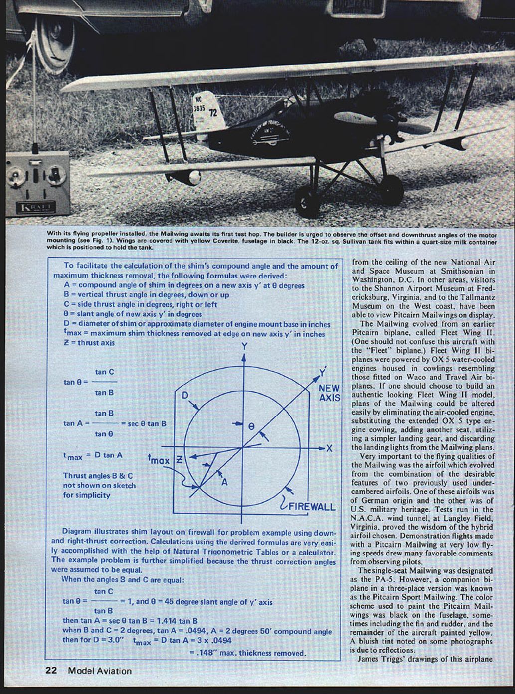
Experience indicated that 2° right and 2° down thrust would be a good first approximation of the angles needed for straight and level flight. Offsets of the base of the engine mount of about 5/32 inch can be used to bring the propeller shaft to the center of the cowl for better appearance; however, this also offsets the engine thrust line and will decrease the thrust correction angles required. These angles, and offsets if desired, together with a 2° positive setting of the stabilizer, should be set for the first test flight. Under these conditions, takeoff and flight should be accomplished with less panic and greater safety. Hopefully, the trim adjustments will be within the limits of the trim available at the transmitter.
Any thought that the engine mount could be machined for thrust correction was discarded when it was found that .148 inch would have to be removed, measured at a point on one edge on a slanted 45° axis from the vertical of a 3‑in. diameter engine mount base. Therefore, a large wedge‑shaped aluminum shim in the form of an annulus (ring or washer) was made and drilled to provide mounting holes as required for the engine mount installation.
It is suggested that 3/16" thick aluminum sheet stock be used for machining this circular wedge shim. Machine your shim, scribe and position your axis; then drill mounting holes. This type of shim will produce the firmest engine mount support.
Wing strut and landing gear strut angles and lengths can be calculated similarly using compound angle formulas. The simplest way to visualize the problem is to draw a pyramid with one corner edge perpendicular to a rectangular base, and with the longest edge representing the strut in question. The perpendicular distance between the attach points or bends and the coordinates of the base can be obtained from the original drawings in accordance with the scale. Projected angles can be measured directly from the drawings; they are unaffected by the scale. Formulas for this type of calculation are listed in Mechanics — Vest Pocket Reference Book. A full explanation of compound angles is contained in Practical Shop Mathematics, Vol. No. 2, by J. H. Wolfe and E. R. Phelps (McGraw‑Hill).
After having prepared a description of a good method to use for applying dope, especially to silk, the winter arrived and the odor of dope would have been offensive, so Coverite was applied. One word of caution: the black color of the Coverite used tended to bleed into the yellow Coverite insignia trim. Glaskote, later used to seal the lettering, would have prevented color bleeding if it had been painted on the contact surface prior to trimming.
Final Installation and Assembly
In the final installation and assembly, methods were devised for retaining the fuel tank, installing a muffler, and providing a good looking landing light lens.
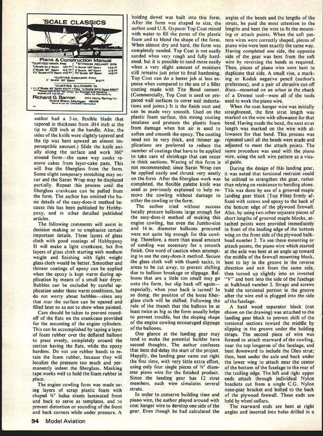
- The square 12‑ounce Sullivan fuel tank fits nicely into a quart‑size cardboard milk carton. Cut, position, and hold the container in place at bulkhead #2 with flat pieces of "apple taffy sticks." It is important to make this installation removable for access to the servos. Another good way is to make the engine bulkhead removable from the firewall complete with the engine and fuel tank.
- The Slim Line Muffler is fine for the engine installation, but it should be modified to install at right angles. Besides looking much better, the muffler can remain on the engine during assembly or removal of the cowling. Viewed from one side, the modified muffler appears in a position that imitates an air inlet for the dummy engine.
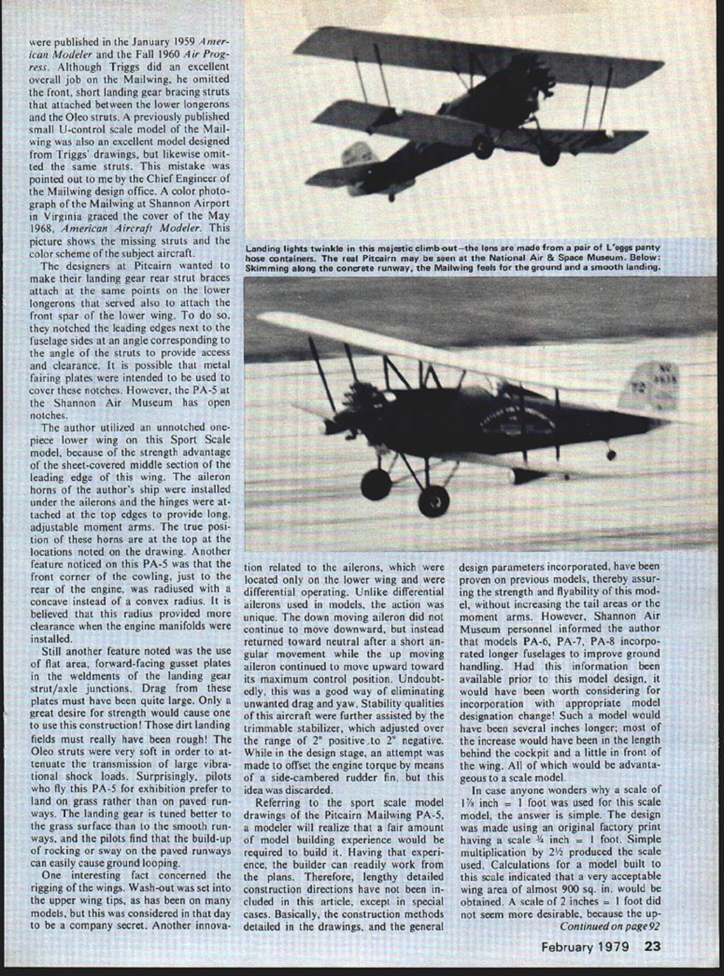
- A very realistic looking lens for the landing lights can be made in about five minutes. Simply acquire a pair of plastic "egg" containers (from L'eggs panty hose packaging). Use the largest end of each egg and scribe the required diameter circle inside by spinning a small compass. Using scissors, cut without cracking to the inscribed circle. Attach lenses to the landing lights with Pliobond cement. For the record, the landing lights were black.
To dress up the 1" piano wire landing gear, it was decided to use large straight plastic soda straws. Short pieces of black neoprene tubing (Sullivan) were split and snapped around the wire to concentrically space two split plastic soda straws. To conceal the split in the straws, two concentric straws were used with splits oriented 180° apart on each wire. The outside split can be covered with a length of invisible Scotch tape before or after painting. Likewise, the ends can be retained by a wrap of the same tape. Tests proved that the tape could be doped. In fact, the dope will stay on the tape with a little loss of gloss; whereas, the dope may tend to flake off the smooth plastic straws when flexed. Sanding the straws lightly to roughen the surface helps. In flight, the straws do not fly off.
Since the oleo struts are larger, it was decided to use cut‑off plastic barrel sections of black felt pens. These sections were split lengthwise by means of an X‑Acto saw and snapped over the piano wire. Concentric spacing was accomplished by a build‑up of split neoprene tubing. Axial shift of these pieces of pen barrels was prevented by "Goo" cement (a rubber‑like modeler's cement the author also applies to prevent wheel collars from coming off, etc.).
Preparation for Flying
In preparation for flying, the landing lights, scale engine, and cowl were removed. A pair of 3‑1/2 in. diameter wheels and a 13‑5/8" propeller were installed. Then the model was balanced with 12 ounces of lead (two 6‑ounce sinkers) on the engine mount. This moved the C.G. forward to about the 30% location. In general, everything was done to compensate for unwanted torque effects and to assure that the model would not fly tail heavy.
Test Flights
The most rewarding part: the test flights of the prototype. Frank Stanton, a friend and fellow club member, agreed to serve as test pilot at our club field at Johnsville N.A.D.C., Warminster, PA. The first check flight was a complete success. Indications were that less ballast could have been used, but the only trim adjustments required were 50% left rudder trim and 100% up elevator trim by means of the transmitter trim adjustments. The airplane flew so well that the second flight became a stunt flight. Frank flew a large portion of a rolling circle; observers noted the excellent manner in which the Pitcairn Mailwing responded in flight. After the test flights Frank's comments were, "It's a good flying airplane! It's a piece of cake to fly!"
At the next flying session, the Pitcairn Mailwing was flown all dressed up for inflight pictures. The ballast weight was reduced to about 8 ounces. Two flights were flown to shoot takeoff, fly‑by, and landing pictures. It was not surprising that this model did not roll fast because the ailerons are only on the lower wing and no differential was utilized. Aileron turns were good, but turns made only using rudder resulted in loss of altitude, which is not unusual.
Indications are that smooth grass flying fields would be preferable to hard surface runways, in agreement with the ground handling of the original airplane. Even when flown with landing lights, scale engine and cowl, the configuration tends to protect them from damage should a ground loop occur. One propeller survived two ground loops on hard runways.
One final note: the author has recently purchased "Giant Round Balloons" made in Mexico and distributed through World Toy House. These balloons look very promising for use when making large engine cowls by the easy‑does‑it method. Of course, modelers should not overlook the possibility of obtaining suitable balloons from HobbyPoxy, the people who originated the method.
Transcribed from original scans by AI. Minor OCR errors may remain.

