
Platyhel
James Gilgenbach
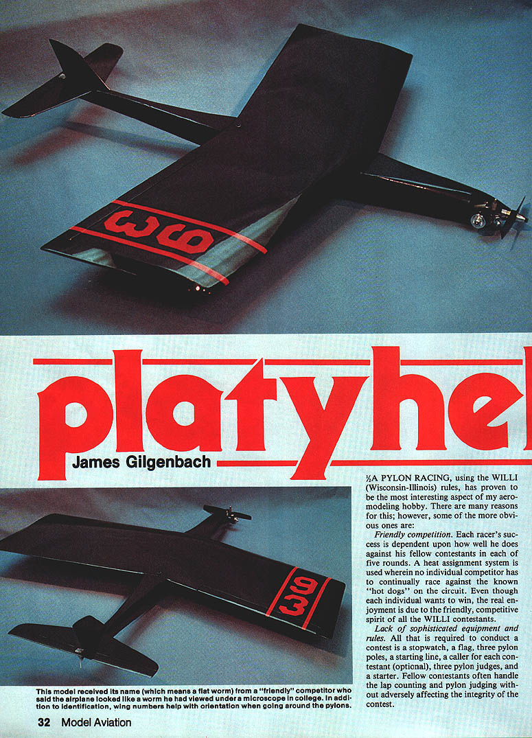
Pylon racing, using the WILLI (Wisconsin–Illinois) rules, has proven to be the most interesting aspect of my aeromodeling hobby. There are many reasons for this; some of the more obvious are:
Friendly competition
- Each racer's success depends upon how well he does against his fellow contestants in each of five rounds.
- A heat-assignment system is used so that no individual has to continually race against the known "hot dogs" on the circuit.
- Although each competitor wants to win, the real enjoyment comes from the friendly, competitive spirit of all the WILLI contestants.
Lack of sophisticated equipment and rules
- All that is required to conduct a contest is a stopwatch, a flag, three pylon poles, a starting line, a caller for each contestant (optional), three pylon judges, and a starter.
- Fellow contestants often handle lap counting and pylon judging without adversely affecting the integrity of the contest.
- Upon the flag signal from the starter, the contestant has 90 seconds to start the engine and get to the starting line. The contestant hand-launches the plane after reaching the starting line. From that point the objective is to make 10 laps around the pylons without cutting and to finish ahead of the other racers.
WILLI rules and aircraft constraints
- Wing: constant chord, minimum area 200 sq. in., minimum thickness 1/8 in.
- Fuselage: at least 2½ in. high (including wing thickness) and minimum cross-sectional area of 6 sq. in.; both dimensions must occur between the wing leading and trailing edges.
- Weight (less fuel): 20 to 32 oz.
- Engines: stock .049 or .051 Cox TDs; no modifications allowed other than lapping the piston and crank. Any kind of needle valve assembly may be used.
- Fuel: normally 25% nitro, supplied by the hosting club. No fuel pressurization allowed.
- No flying wings or pod-and-boom aircraft are allowed.
- A means of remotely stopping the engine is required.
Winning strategy
Don't assume the WILLI circuit rules neutralize contestant ingenuity. On any given day, techniques that helped me consistently win are the same regardless of whom or where I was racing. Through experimentation I reached the following conclusions:
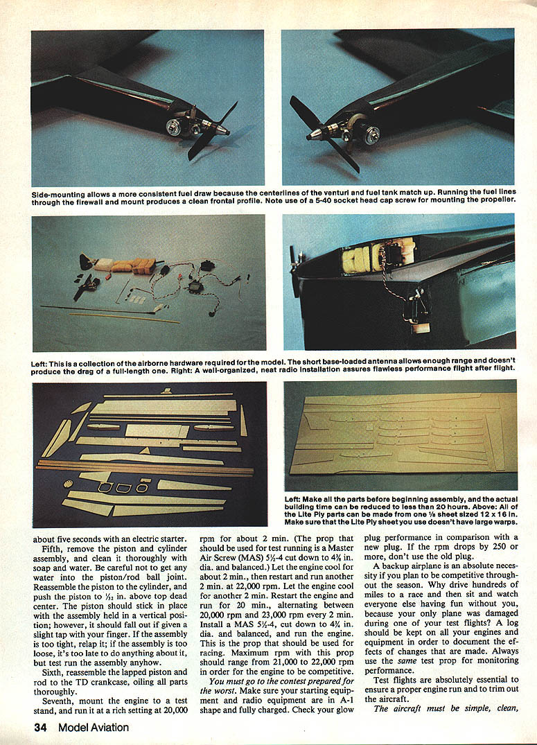
- The Cox TD engine must run reliably at full power. Achieve this by properly lapping the engine, correctly mounting the engine and fuel tank, and ensuring fuselage rigidity to avoid vibration.
- Go to the contest prepared for the worst: keep starting equipment and radio equipment in A-1 shape and fully charged. Check glow-plug performance against a new plug—if rpm drops by 250 or more, don't use the old plug.
- A backup airplane is essential. Keep a log on all engines and equipment to document the effects of changes. Always use the same test prop for monitoring performance.
- Test flights are essential to ensure a proper engine run and to trim the aircraft.
Engine lapping and break-in (recommended procedure)
An easy way to lap a Cox piston and cylinder is to use an old Cox Babe Bee crankcase assembly and an electric starter.
- Inspect the piston and cylinder for loose metal particles, burrs, gouges, or scratches. Remove loose particles and burrs. If gouges or scratches are serious, replace the piston and cylinder assembly.
- Using a rod-setting tool, snug up the rod in the piston socket to eliminate end play. Do not overtighten—the rod should still freely pivot side to side and rotate in the piston.
- Add a light oil to the rod, crankpin hole, and piston ball joint. Install the piston and cylinder onto an old Babe Bee or other Cox .049/.051 crankcase that has approximately 1/32 in. removed from the portion where the cylinder mounts. This permits the piston to travel above its normal top limit for lapping.
- Apply automotive polishing compound to the cylinder with the piston at the bottom of its stroke. Crank the assembly by hand to work in the compound, then turn the engine with an electric starter for short intervals (about five seconds at a time) to lap the surfaces.
- Remove the piston and cylinder and clean thoroughly with soap and water. Take care to remove all water from the piston/rod ball joint. Reassemble the piston and cylinder and push the piston 1/32 in. above top dead center—the piston should stick in place when the assembly is held vertical.
- Reassemble the lapped piston and rod to the TD crankcase, oiling all parts thoroughly.
- Mount the engine to a test stand and run it through a break‑in routine:
- Use a Master Airscrew (MAS) 5-3/4 prop cut down to 4-3/4 in. dia. and balanced for test running.
- Run at a rich setting at 20,000 rpm for about 2 minutes. Let cool 2 minutes.
- Run at 22,000 rpm for about 2 minutes. Let cool 2 minutes.
- Restart and run for a total of 20 minutes, alternating every 2 minutes between ~20,000 rpm and ~23,000 rpm.
- Install the racing prop (MAS 5-3/4 cut down to 4-3/4 in. dia., balanced). Maximum rpm with this prop should range from 21,000 to 22,000 rpm for competitive performance.
Preparation checklist
- Ensure starting and radio equipment are fully charged and in top condition.
- Check glow-plug performance against a new plug.
- Bring a backup airplane and keep a log of engines and equipment.
- Always test-fly to verify engine run and trim.
Construction
General
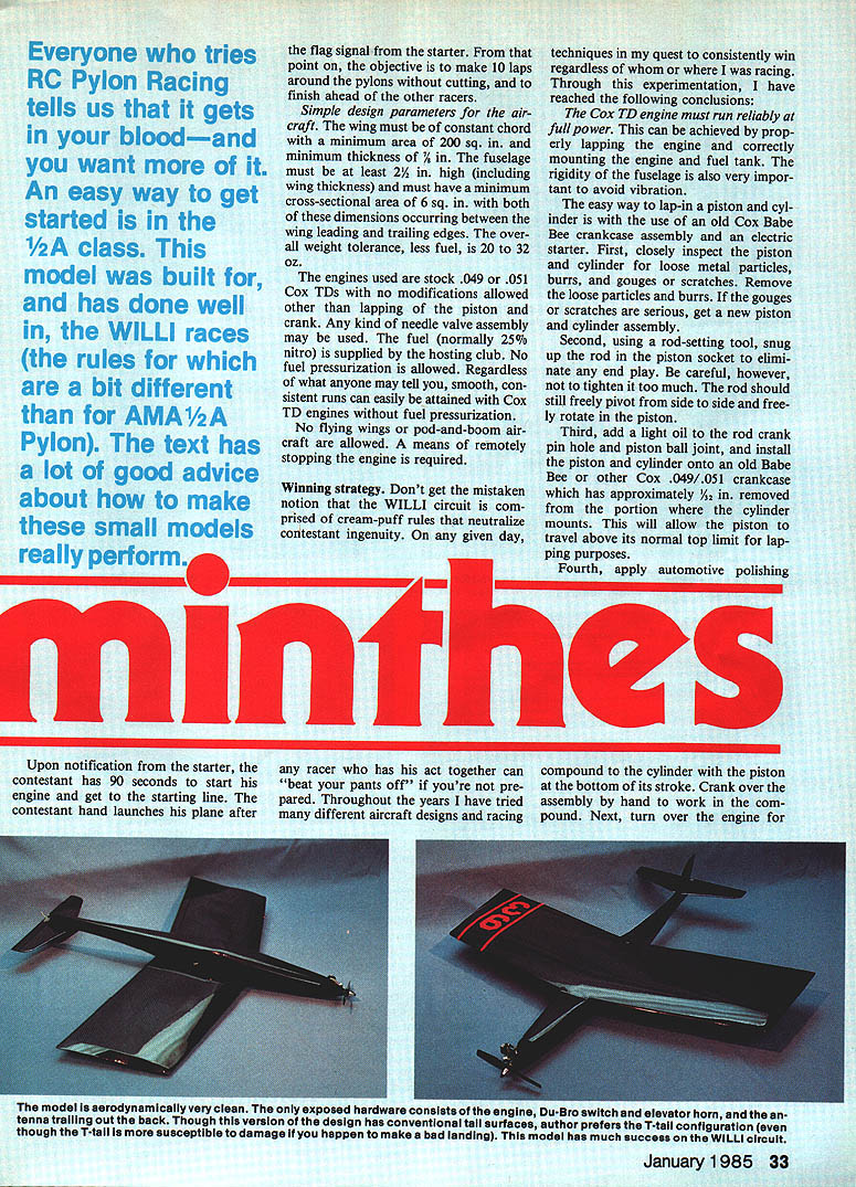
The aircraft must be simple and aerodynamically clean. Exposed hardware should be minimal: engine, DuBro switch, elevator horn, and the antenna trailing out back. The author prefers a T-tail configuration, although conventional tall surfaces are used in this version. T-tails are more susceptible to damage on bad landings but have been successful on the WILLI circuit.
Use thick cyanoacrylate (CyA) for some assembly steps as recommended below.
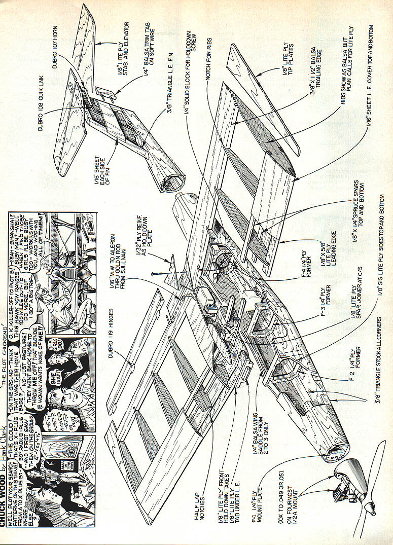
Wing (building)
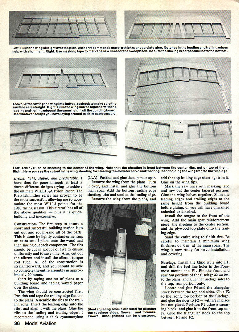
- Position and glue the top main spar. Remove the wing from the plans, turn it over, and install and glue the bottom main spar.
- Add the bottom leading edge sheeting; trim and sand at the leading edge.
- Remove the wing from the plans and add the top leading edge sheeting; trim it. Glue on the wing tips.
- Mark the saw lines with masking tape and saw out the center tapered portion. Glue the wing halves together.
- Shim the leading and trailing edges at the same height from the building board before gluing, or you will introduce unwanted anhedral or dihedral.
- Install the tongue to the front of the wing. Add the main spar reinforcement piece, sheeting to the center section, and the plywood top plate onto the trailing edge.
- Sand the entire wing to finish size, keeping a minimum wing thickness of 1/16 in. at the main spars.
- Prepare for servo installation and covering.
Fuselage (building)
- Install the blind nuts into F1, and drill the fuel line holes in the front mount and F1.
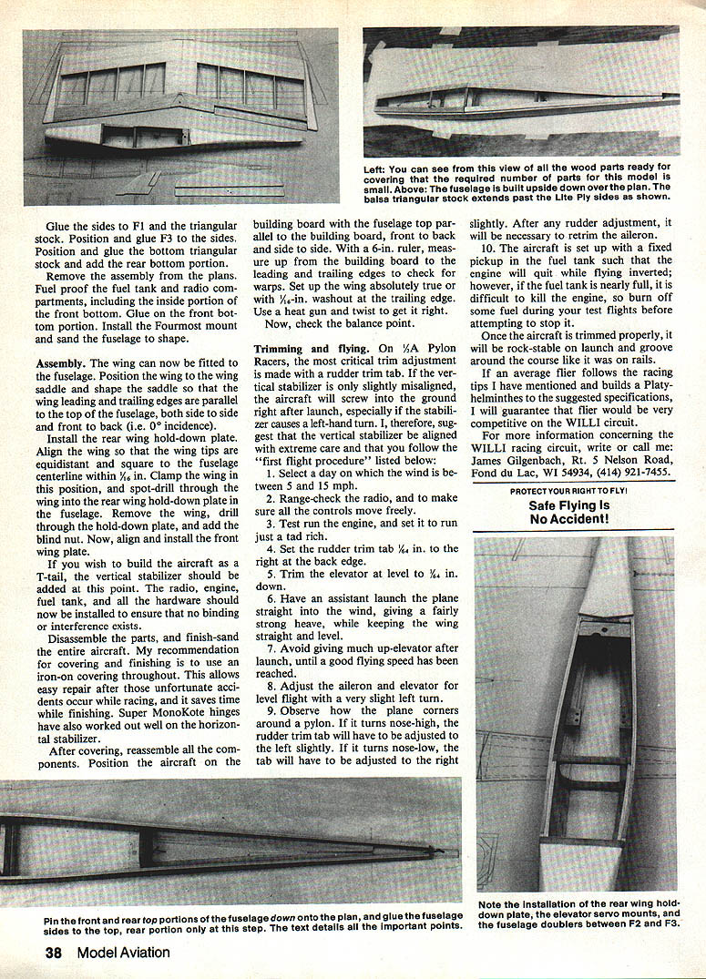
- Pin the front and rear top portions of the fuselage to the plans, and glue the fuselage sides to the top, rear portion only.
- Locate and glue F4 and the triangular stock between the top and sides.
- Glue F2 to the front top portion of the fuselage, and glue the sides to F2 (with F3 in place but not glued).
- Position F1 using a squaring block and glue it to the front top only. Glue the triangular stock to the top between F1 and F2.
- Glue the sides to F1 and the triangular stock. Position and glue F3 to the sides. Position and glue the bottom triangular stock and add the rear bottom portion.
- Remove the assembly from the plans. Fuel-proof the fuel tank and radio compartments, including the inside portion of the front bottom. Glue on the front bottom portion.
- Install the Fourmost mount and sand the fuselage to shape.
Assembly
- Fit the wing to the fuselage. Position the wing to the wing saddle and shape the saddle so the wing leading and trailing edges are parallel to the top of the fuselage, both side to side and front to back (i.e., 0° incidence).
- Install the rear wing hold-down plate. Align the wing so that the wing tips are equidistant and square to the fuselage centerline within 1/16 in. Clamp the wing in position and spot-drill through the wing into the rear hold-down plate in the fuselage. Remove the wing, drill through the hold-down plate, and add the blind nut. Now align and install the front wing plate.
- If building a T-tail, add the vertical stabilizer at this point.
- Install the radio, engine, fuel tank, and all hardware to ensure no binding or interference exists.
- Disassemble parts and finish-sand the entire aircraft.
- Recommended covering and finishing: use an iron-on covering throughout for easy repair and time savings. Super MonoKote hinges have worked well on the horizontal stabilizer.
- After covering, reassemble all components. Position the aircraft on the building board with the fuselage top parallel to the board, front to back and side to side. Measure up from the board to the leading and trailing edges with a 6-in. ruler to check for warps.
- Set the wing absolutely true or with 1/8-in. washout at the trailing edge. Use a heat gun and twist to get it right. Now check the balance point.
Trimming and flying
On 1/2A pylon racers, the most critical trim adjustment is made with a rudder trim tab. If the vertical stabilizer is slightly misaligned, the aircraft may screw into the ground right after launch, especially if the stabilizer induces a left-hand turn. Align the vertical stabilizer with extreme care and follow this first-flight procedure:
- Select a day with wind between 5 and 15 mph.
- Range-check the radio and ensure all controls move freely.
- Test-run the engine and set it to run just a tad rich.
- Set the rudder trim tab 1/8 in. to the right at the back edge.
- Trim the elevator at level to 1/8 in. down.
- Have an assistant launch the plane straight into the wind, giving a fairly strong heave while keeping the wing straight and level.
- Avoid giving much up-elevator after launch until a good flying speed has been reached.
- Adjust the aileron and elevator for level flight with a very slight left turn.
- Observe how the plane corners around a pylon. If it turns nose-high, adjust the rudder trim tab slightly to the left. If it turns nose-low, adjust the tab slightly to the right. After any rudder adjustment, retrim the aileron.
- The aircraft is set up with a fixed pickup in the fuel tank such that the engine will quit while flying inverted; however, if the fuel tank is nearly full it can be difficult to kill the engine. Burn off some fuel during test flights before attempting to stop it.
Once trimmed properly, the aircraft should be rock-stable on launch and groove around the course like it was on rails. If an average flier follows the racing tips above and builds a Platyhelminthes to the suggested specifications, that flier should be very competitive on the WILLI circuit.
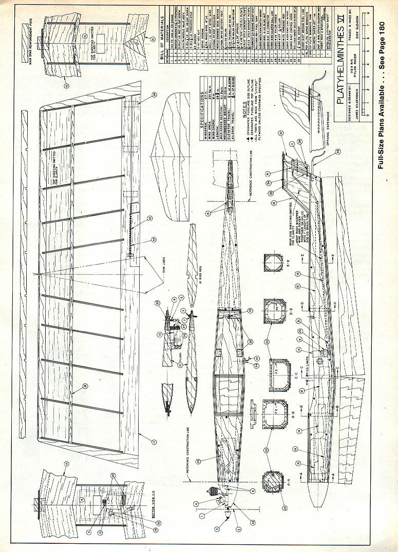
PLATYHELMINTHES XI
Full-Size Plans Available ... See Page 180
BILL OF MATERIALS
(Refer to full-size plans for a complete bill of materials.)
SPECIFICATIONS
(Refer to full-size plans for detailed specifications.)
NOTES
- Use the same test prop for performance monitoring.
- Keep detailed logs of engine runs, props used, and trim settings to document the effects of changes.
For more information concerning the WILLI racing circuit, write or call: James Gilgenbach Rt. 5 Nelson Road Fond du Lac, WI 54934 (414) 921-7455
Transcribed from original scans by AI. Minor OCR errors may remain.

