
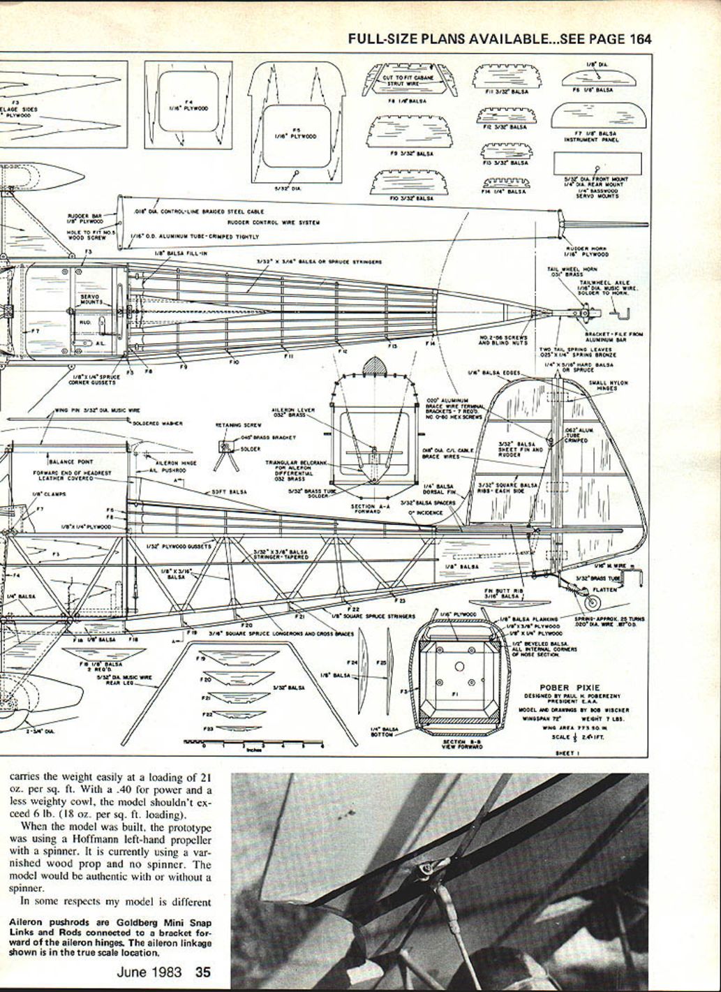
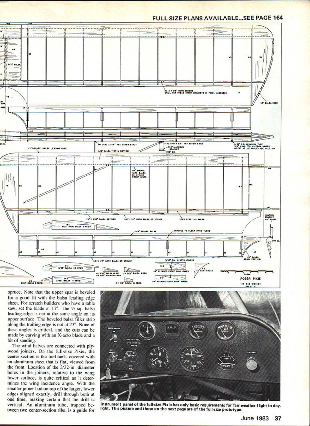
Pober Pixie
Bob Wischer
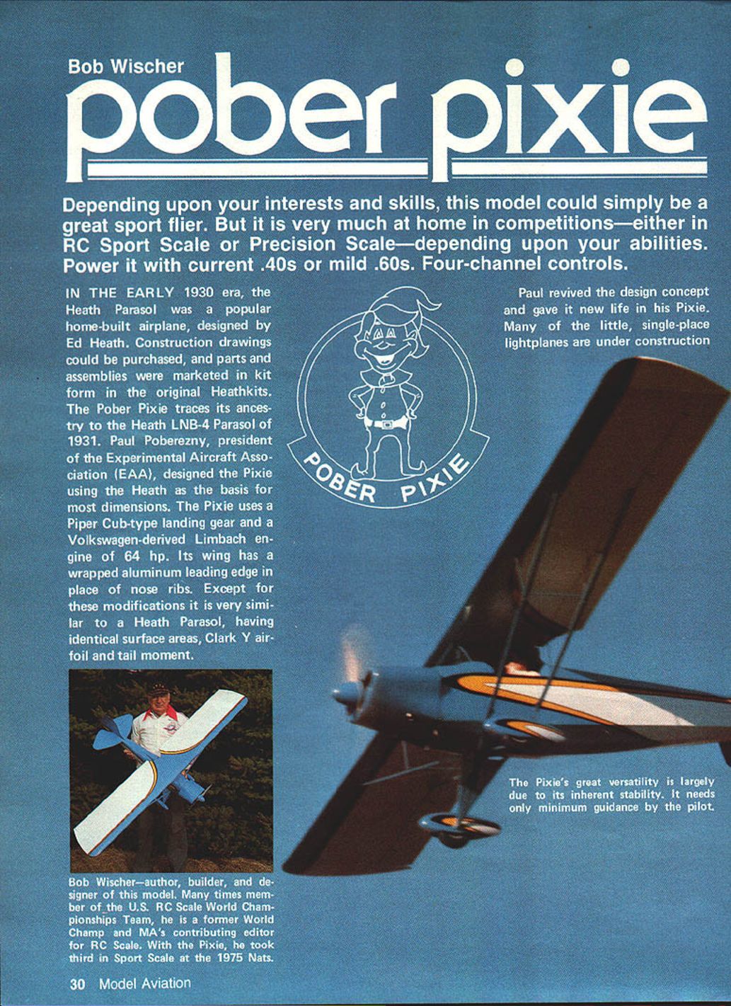
Depending upon your interests and skills, this model can simply be a great sport flier or a competitive ship in RC Sport Scale or Precision Scale contests. Power it with modern .40s or mild .60s. Four-channel controls.
Background
- In the early 1930s the Heath Parasol was a popular home-built airplane designed by Ed Heath. Construction drawings could be purchased, and parts were marketed in kit form as Heathkits.
- The Pober Pixie traces its ancestry to the Heath LNB-4 Parasol of 1931. Paul Poberezny, president of the Experimental Aircraft Association (EAA), designed the Pixie using the Heath for most dimensions.
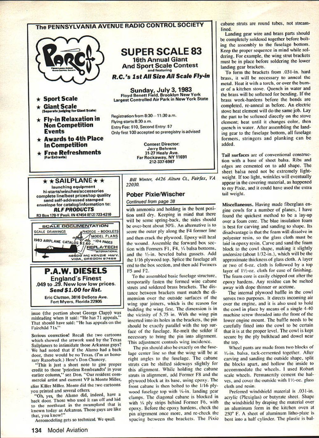
- The full-size Pixie uses a Piper Cub–type landing gear and a Volkswagen-derived Limbach engine of 64 hp. Its wing has a wrapped aluminum leading edge in place of nose ribs; otherwise it is very similar to the Heath Parasol, with identical surface areas, Clark Y airfoil, and tail moment.
- Paul revived the design and many single-place Pixies are under construction or flying today.
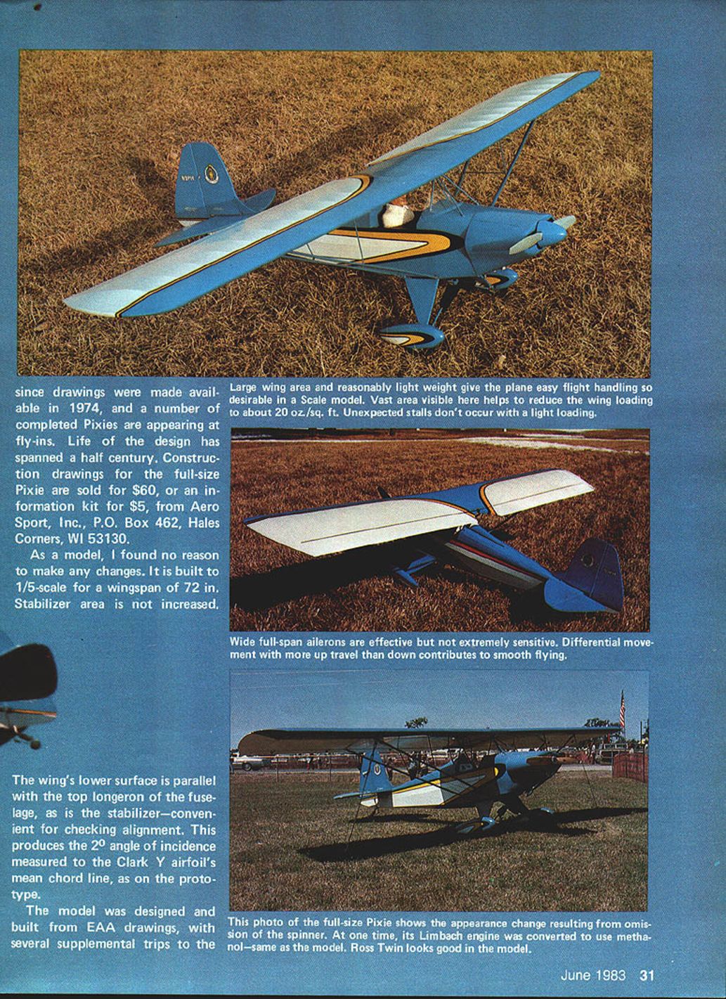
- Drawings were made available in 1974. Construction drawings for the full-size Pixie are sold for $60, or an information kit for $5, from Aero Sport, Inc., P.O. Box 462, Hales Corners, WI 53130.
The Scale Model
- The model is built to 1/5 scale with a wingspan of 72 in. Stabilizer area is not increased.
- The wing lower surface is parallel with the top longeron of the fuselage, as is the stabilizer, producing a 2° angle of incidence measured to the Clark Y airfoil's mean chord line (as on the prototype).
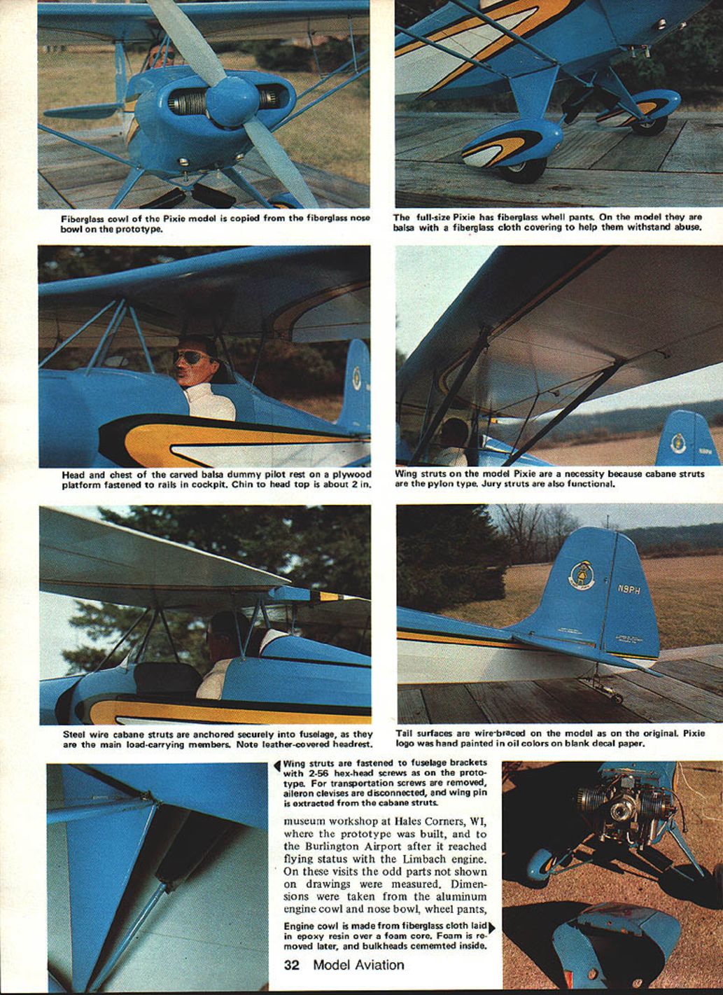
- Wing struts fasten to fuselage brackets with 2-56 hex-head screws as on the prototype. For transport, the screws are removed, aileron linkages disconnected, and a wing pin extracted from the cabane struts.
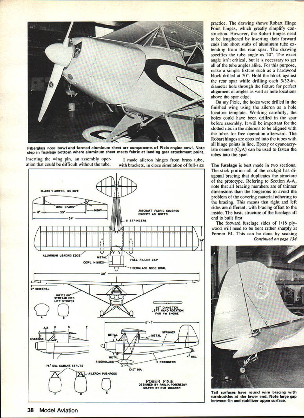
- The model's engine cowl is a fiberglass nose bowl copied from the prototype. Wheel pants on the full-size are fiberglass; on the model they are carved balsa covered with fiberglass cloth.
- I carved a balsa dummy pilot that rests on a plywood platform fastened to rails in the cockpit; chin, head and top are about 2 in. above the deck.
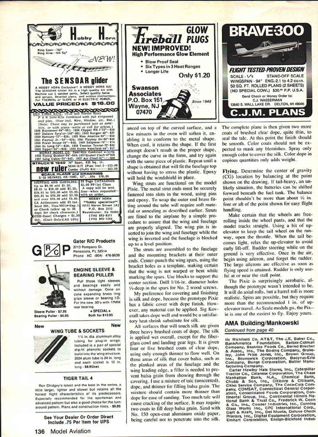
- Tail surfaces are wire-braced on the model. The original Pixie logo was hand-painted in oil colors; blank decals printed on decal paper were used for some markings.
Ailerons and Control Characteristics
- On first inspection the ailerons appear disproportionately large—almost full-span and 3 in. wide on the model. This has caused no problems in flight; the rudder isn't required for aileron turns.
- Frise-type ailerons were used because the aileron hinge line on the prototype is located behind the lower leading edge; I copied that feature. The off-center bellcrank produces differential travel (more up-aileron than down), which contributes to scale-like flight characteristics.
- Prototype differential: 3 in. up / 2 in. down. Model differential (copied from the EAA drawings): 3/8 in. up / 3/16 in. down.
- Elevator travel: 1 in. each side. Rudder travel: 1-3/4 in. each side of center.
Weight, Balance and Power
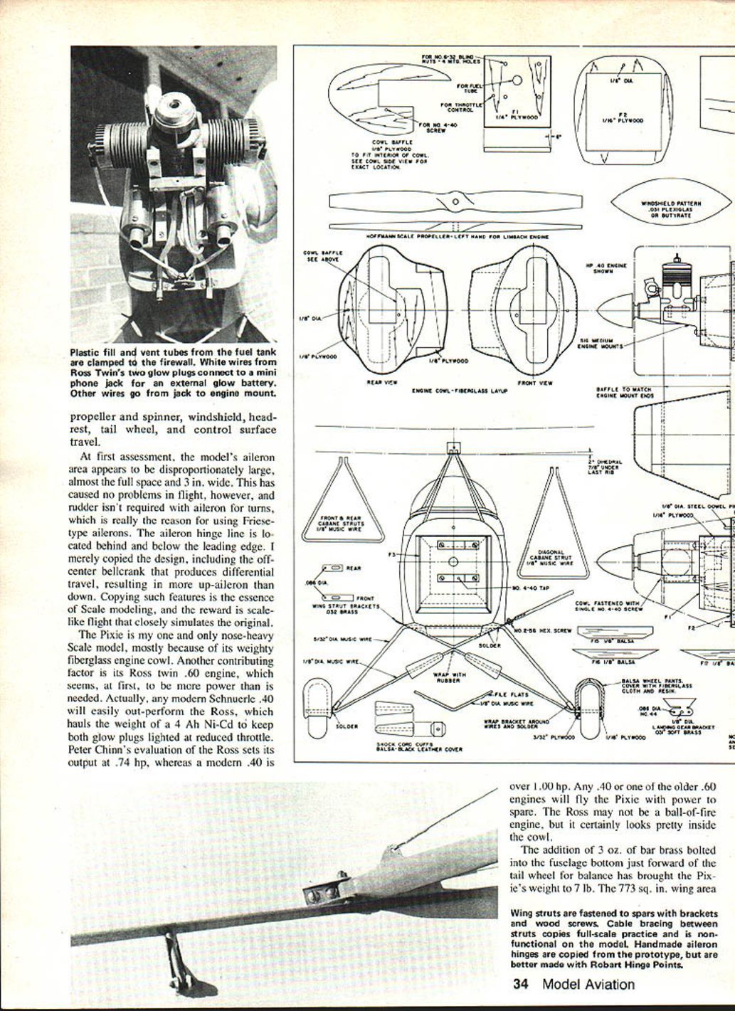
- The scale model is somewhat nose-heavy, mostly because of its fiberglass engine cowl and the original Ross twin .60 engine used. A modern Schnuerle .40 will easily out-perform the Ross while saving weight.
- A 4-Ah Ni-Cd pack will keep both glow plugs lighted during reduced-throttle operations.
- Peter Chinn's evaluation of the Ross sets its output at about 0.74 hp; modern .40s are typically over 1.00 hp.
- The addition of about 3 oz. of brass bolted into the fuselage bottom just forward of the tailwheel brought the Pixie's weight to 7 lb.
- Wing area: 773 sq. in.; wing loading: about 21 oz. per sq. ft.
- With a .40 engine and a lighter cowl the model should be near 6 lb. (about 18 oz. per sq. ft. loading).
Construction
General approach
- I prefer building the wing first to simplify fitting the cabane struts to the spars.
- Build the flat-bottomed wing halves directly over the drawing on a flat building surface (a hollow-core door works well).
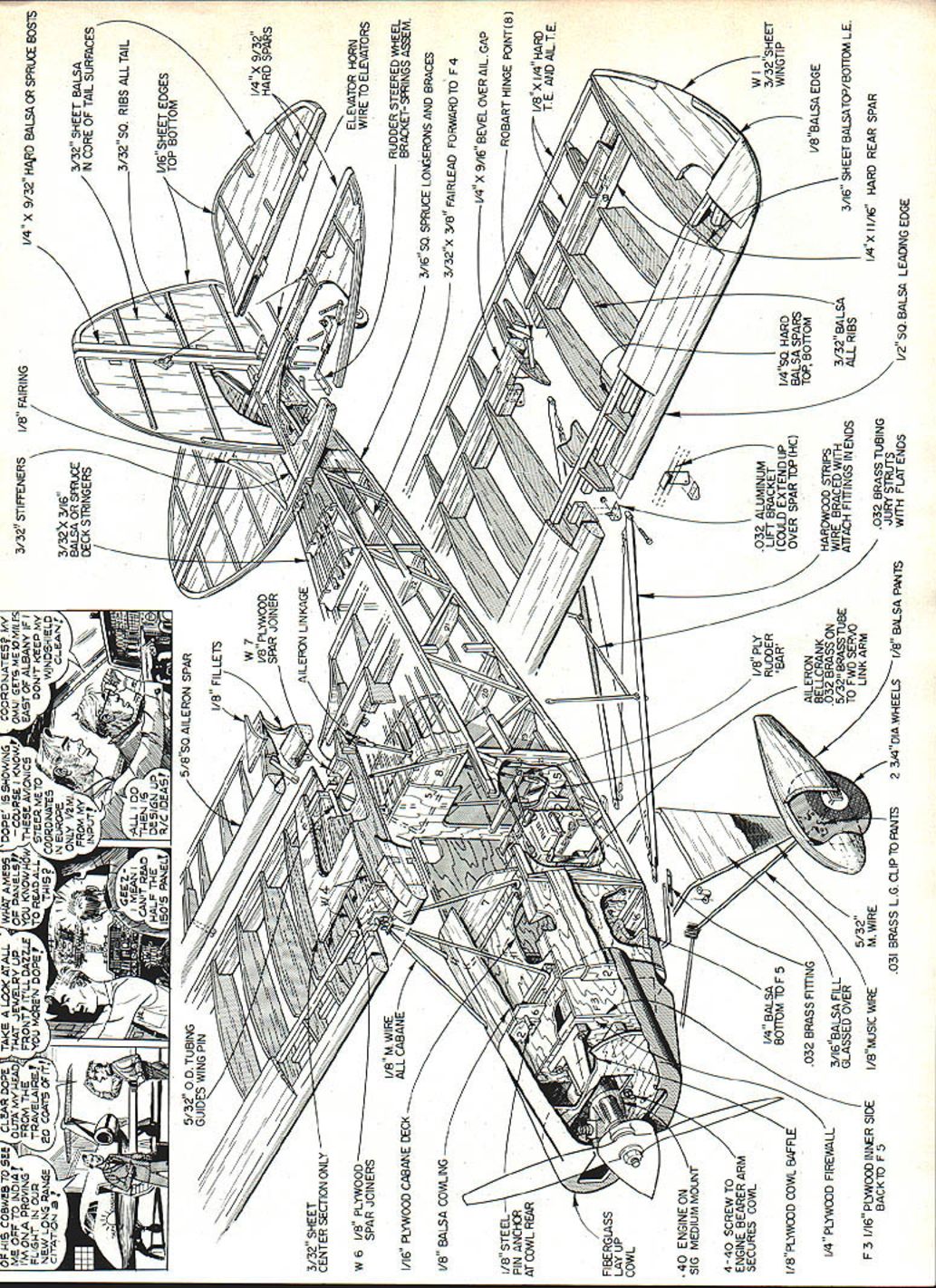
Wing spars and leading/trailing edges
- Front spars can be hard balsa or spruce. The upper spar is beveled for a good fit with the balsa leading edge sheet.
- For scratch builders with a table saw: set the blade at 17° for the upper spar bevel. The 1/2 in. square balsa leading edge is cut at the same angle on its upper surface. The beveled balsa filler strip along the trailing edge is cut at 23°. These angles are not critical and may be carved and sanded if preferred.
Center section and wing joiners
- Wing halves are connected with plywood joiners. On the full-size Pixie the center section is the fuel tank and is covered with an aluminum sheet that is flat when viewed from the front.
- The location of the 3/32 in. diameter holes in the joiners relative to the wing lower surface is critical because it determines wing incidence angle. With the smaller joiner laid on top of the larger, lower edges aligned exactly, drill through both at once with the drill vertical.
- An aluminum tube trapped between two center-section ribs is a guide for inserting the wing pin.
Aileron hinges
- The drawing shows Robart Hinge Point hinges, which simplify construction. I made brass-tube hinges to closely simulate full-size practice.
- If using Robart hinges, lengthen them by inserting their forward ends into short stubs of aluminum tube extending from the rear spar.
- The drawing specifies a tube angle of 20°. Use a simple fixture (hardwood block drilled at 20°) to get consistent holes and angles while drilling 5/32 in. diameter holes through the fixture into the rear spar.
- Epoxy or cyanoacrylate will fasten the tubes into the spar. Ensure slotted ribs in the ailerons align with the tubes for free operation.
Fuselage
- Build the fuselage in two sections. The stick portion aft of the cockpit has diagonal bracing duplicating the prototype structure. Bracing members are thinner than the longerons to avoid the covering adhering to the bracing.
- Forward fuselage sides of 1/16 in. plywood need to be bent sharply at Former F4. Soak with ammonia and hold in the bent position until dry, over-bend about 50% to allow for spring-back. Alternatively, score the outer ply and crack along the F4 line, then epoxy to repair.
- Assemble the forward box section with Formers F1 and F4, 1/4 in. balsa bottoms, 3/8 in. beveled balsa gussets, and a 1/16 in. plywood top. Splice the aft fuselage to the box section and add Formers F5 and F2.
Cabane struts and wing pin alignment
- Temporarily fasten formed wire cabane struts and soldered brass brackets to the fuselage. Distance between brackets must match the outside dimension over the wing spar joiners—build the wing first to set this.
- With the wing pin inserted, the pin must be parallel with the fuselage top surface and on the fuselage center line so the wing is at right angles to the fuselage. Re-melt solder as necessary to align the pin.
- Add Former F8 and the plywood block at its base with epoxy while holding alignment. The front cabane is bolted to the 1/16 in. plywood fuselage top with 1/8 in. landing gear clamps. Block in the diagonal cabane with 1/16 in. ply strips behind Former F6 and epoxy.
Landing gear, brass brackets and annealing
- Landing gear wire and brass parts should be completely soldered together before bolting the assembly to the fuselage bottom. Keep the proper solder sequence (for example, strut brackets must be in place before soldering lower landing gear brackets).
- To form brackets from .031 in. hard brass, anneal the metal: heat with a torch or on a stove element until it changes color, then quench in water. Re-anneal if the brass work-hardens during bending.
Tail surfaces
- Conventional construction with a base of sheet balsa; ribs and edges cemented on to add shape. Do not use extremely lightweight sheet balsa—too light and wrinkles in the covering may appear. A somewhat heavier sheet would have been beneficial on my Pixie.
Fiberglass cowls
- Best method: lay up fiberglass cloth over a foam core (blue insulation foam is easiest to carve and sand). The foam dissolves in polyester resin, so use epoxy resin with the glass cloth.
- Carve and sand the foam to the cowl shape slightly undersize (~1/32 in.). Use one or two layers of 6-oz cloth followed by a top layer of 1.5-oz cloth for finishing ease. Remove foam core after epoxy hardens; melt residue with dope thinner or acetone.
- Internal plywood baffle directs incoming air and holds the cowl in place by a single 4-40 screw threaded into the front of the lower engine mount. The cowl is further secured by the ply bulkhead and a dowel near the top.
Wheel pants
- Make wheel pants from two blocks of 3/8 in. balsa tack-cemented together. Carve the outside shape, split the blocks, hollow to accommodate the wheels (Robart scale wheels recommended), permanently cement halves, and cover the outside with 1.5-oz glass cloth and resin.
Windshield and spinner
- Preferred windshield material: 0.031 in. acrylic (Plexiglas) or butyrate sheet. Shape by draping over an aluminum form in a kitchen oven at about 250°F. Use an aluminum litho-plate bent into a half cylinder as a former.
- The propeller spinner may be used or omitted; the model can be authentic either way.
Wing struts and fittings
- Wing struts on the model are functional. Metal strut ends must be securely fastened into slots in the wood using pins and epoxy.
- Wrap the outer end brass fitting around the tube (anneal if necessary) to form the fitting. Fit struts to the airplane with the wing pin inserted and the wing inverted; block the fuselage to level before drilling spars.
- Center-punch spars using bracket holes as a template. Drill 11/16 in. diameter holes 1/4 in. deep in the spars for No. 2 wood screws.
Servos and linkages
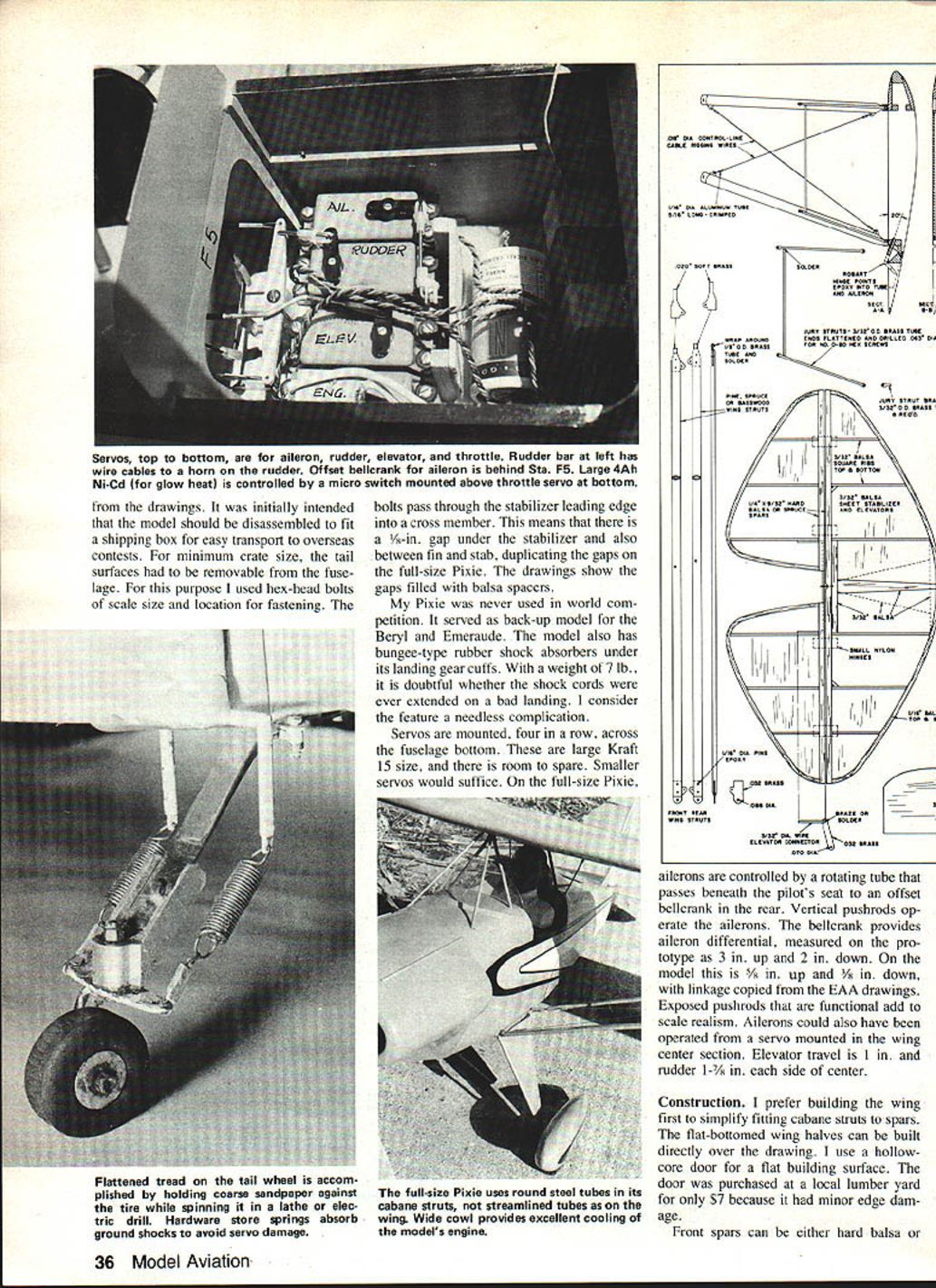
- Servos were mounted four in a row across the fuselage bottom (large Kraft 15 size in my model). Smaller servos will suffice.
- On the full-size Pixie, ailerons are controlled by a rotating tube under the pilot's seat to an offset bellcrank in the rear; vertical pushrods operate the ailerons. Exposed functional pushrods add scale realism.
- On my model, aileron pushrods are Goldberg Mini Snap Links and rods connected to a bracket forward of the aileron hinges—true scale location.
- The aileron linkage shown on the drawings is in the scale location; aileron hinges can be Robart Hinge Points for simpler construction (lengthen their forward ends into short aluminum stubs as noted).
Covering and finishing
- I prefer silk and dope because the prototype has a fabric cover and dope finish, though any modern covering can be used. Sig Koverall is a suitable heat-shrunk substitute.
- All surfaces that will touch silk receive three heavy brushed coats of dope before covering.
- Apply silk overall except for the fiberglass cowl and landing gear legs. Give the silk four or five brushed coats of clear dope using only enough thinner to flow well.
- On silk covering balsa planked areas (fuselage planking and wing leading edges), fill balsa grain with a mixture of talc (unscented), dope, and thinner. Use more thinner than dope for ease of sanding. Too much talc causes cracking. Two coats may be required for deep grain; sand with No. 150 open-coat aluminum oxide paper.
- After sanding and sealing the talc, apply two more thin coats of clear dope. Color coats should be sprayed only enough to cover—the more color dope used, the more weight added.
Miscellaneous Notes
- I visited the museum workshop at Hales Corners, WI, where the prototype was built, and later the Burlington Airport after it reached flying status with the Limbach engine. On those visits I measured odd parts not shown on the drawings. Dimensions were taken from the aluminum engine cowl and nose bowl, wheel pants, and other components.
- The model was designed so it could be disassembled to fit a shipping box for overseas contests. Tail surfaces were made removable with scale-size hex-head bolts passing through the stabilizer leading edge into a cross member. This creates a 1/2 in. gap under the stabilizer and between fin and stab, duplicating the gaps on the full-size Pixie (drawings show these filled with balsa spacers).
- My Pixie was never used in world competition; it served as a backup model for the Beryl and Emeraude. It has bungee-type rubber shock absorbers under its landing gear cuffs, which for a 7 lb. model are likely unnecessary.
- Handmade aileron hinges closely simulate the prototype, but Robart Hinge Points are recommended for simplicity and reliability.
Flying
- Determine the center of gravity (CG) by balancing at the point shown on the drawing. If the model is tail-heavy (unlikely), move batteries forward beneath the fuel tank. The balance point shouldn't be more than about 1/4 in. forward or aft of the indicated point for easy handling.
- Ensure wheels are free-rolling inside the wheel pants and the model tracks straight.
- Use a bit of up-elevator to keep the tailwheel on the runway while opening the throttle. When the tail becomes light, relax up-elevator to avoid early lift-off. Rudder steering on the ground is effective.
- Once airborne, begin using aileron and rely principally on aileron control—the large ailerons are effective as soon as flying speed is attained. Rudder is mainly useful at or near stall speeds.
- The Pixie is surprisingly aerobatic: it will do axial rolls, but a barrel roll looks more realistic. Spins are possible but require more than the recommended 1 in. of up-elevator travel.
- As a scale model the Pixie is one of the easiest to fly. Enjoy yours.
Transcribed from original scans by AI. Minor OCR errors may remain.

