
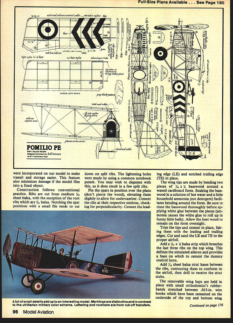
Pomilio PE
Bill Noonan
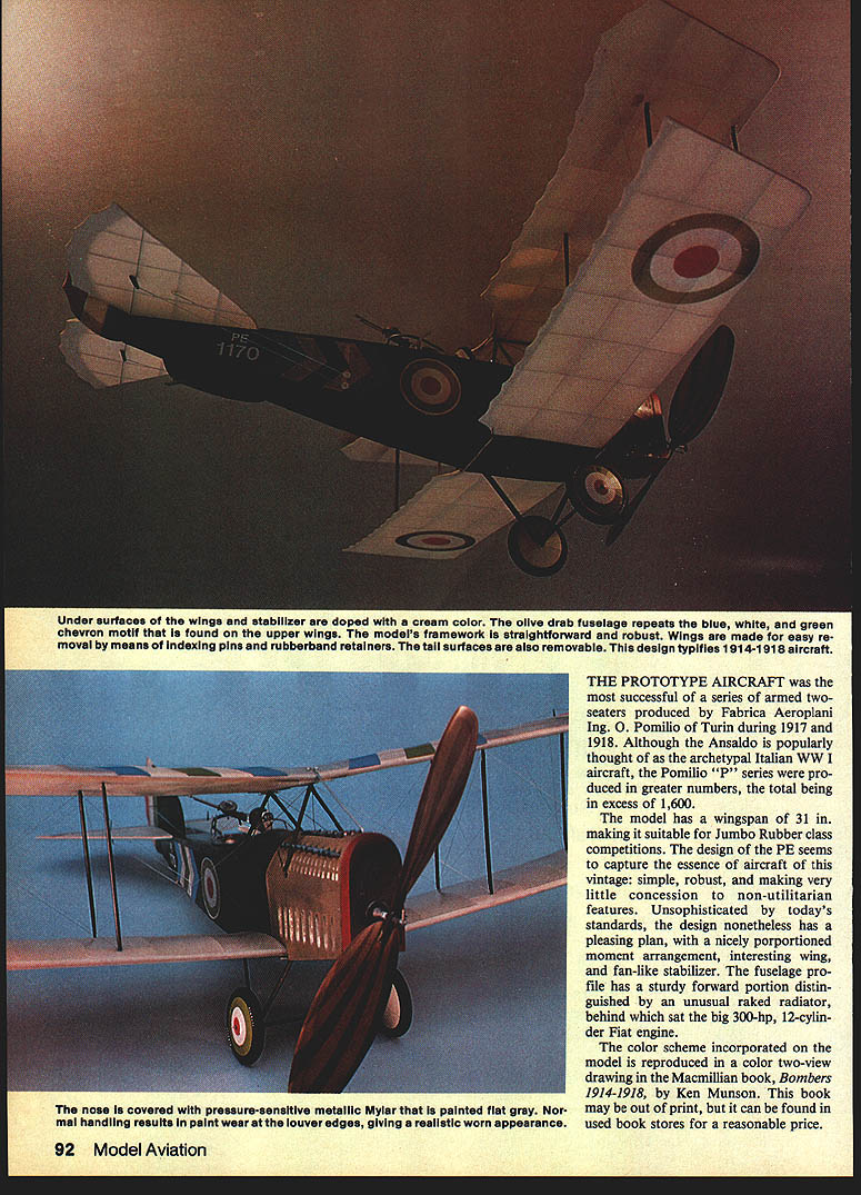
The Pomilio PE was the most successful of a series of armed two-seaters produced by Fabbrica Aeroplani Ing. O. Pomilio of Turin during 1917–1918. Although Ansaldo is often thought of as the archetypal Italian WW I aircraft, the Pomilio P series were produced in greater numbers (more than 1,600). The model described here has a 31 in. wingspan, making it suitable for Jumbo Rubber class competitions (scale: 13/16 in. = 1 ft).
The design captures the essence of aircraft of the vintage: simple, robust, and utilitarian. It features a nicely proportioned layout, an interesting wing, a fan-like stabilizer, and a fuselage with a sturdy forward portion distinguished by an unusual raked radiator behind the 300-hp, 12-cylinder Fiat engine. The color scheme used on the model is based on a two-view in Ken Munson’s Bombers 1914–1918.
Fuselage construction
- Longerons: Laminate longerons by cementing 1/8 x 3/16-in. balsa to 1/16-in. sq. balsa to form an L-shaped piece (see enlarged detail on the plans). This allows the tissue covering to be cemented along the edge of the 1/16-in. balsa.
- Sides: Lay the longerons over the side-view plans and cement in the upright parts. Make a right and a left side. If using the laminated longeron, cut 1/32-in. sheet balsa plates at the nose and set them flush with each side. You may substitute 3/32-in. sq. balsa to simplify construction.
- Assembly: After the glue is dry, invert both side frames and align them over the top-view plans. Cement the tail posts together and work forward, cementing crosspieces at their stations. Check symmetry as you go. Clamp the nose during this operation since the cockpit area is the widest part.
- Rubber anchor reinforcement: The two uprights that accept the 3/16-in.-dia. aluminum-tube rubber anchor at the tail should be made of hard 1/16-in. balsa and backed with a 1/16-in. plywood doubler. Rampant rubber motors are unforgiving to the fuselage interior.
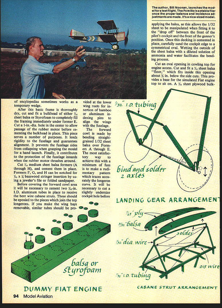
- Bulkhead E and rubber motor passage: Cut and fit bulkhead E from 1/16-in. sheet balsa. Fill the framing immediately under former E with Styrofoam and cut a 1-in.-dia. hole in its center to allow the rubber motor to pass through before cementing the bulkhead. This bulkhead lends rigidity, guarantees alignment, prevents side collapse when launching, and protects the fuselage innards.
- Formers: Cut medium-sheet balsa formers F through H and cement in place. Formers F, G, H can be notched for 1/32-in. basswood stringer insertion using a jeweler’s file and folded sandpaper.
Forward cowl and wing-root fittings
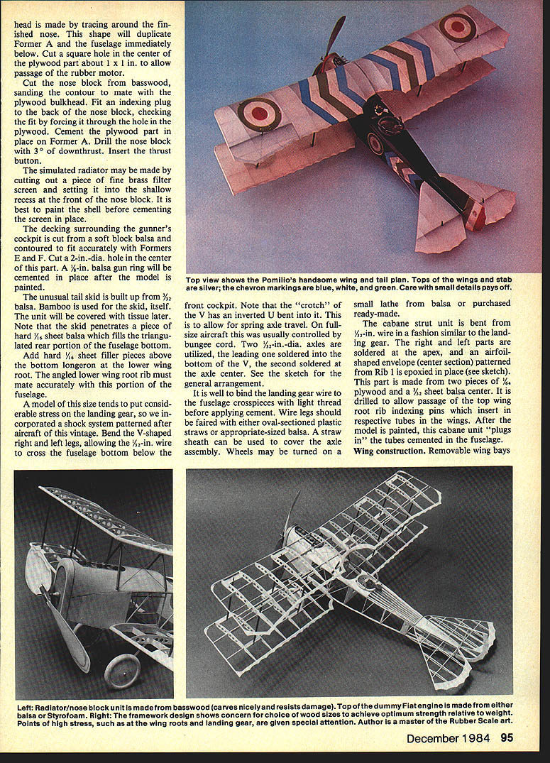
- Cowl: The forward cowl is made by bending straight-grained 1/32-in. sheet balsa over Formers A through E. Make a rudimentary paper pattern tracing the longeron curve, cut the cockpit hole slightly undersize, and then fit the balsa. Wetting the outside of the sheet with a diluted ammonia-and-water solution helps bending. Cut an oval opening in the cowling top for engine access and fit a 1/32-in. sheet balsa "floor" about 1/8 in. below the top cut to support the simulated Fiat engine.
- Cabane and indexing tubes: Before covering the forward cowl, cement two 1/8-in.-I.D. aluminum tubes (epoxied) into the pieces that join the top longerons; these receive the bent-wire cabane struts. If the wing bays are removable, provide similar tubes at the lower wing roots to accept indexing pins that align wings and fuselage. A 1/32-in. plywood bulkhead is cemented at the lower wing roots for insertion of bamboo or aluminum indexing pins.
- Removable bays: The pieces joining the top longerons make the wing bays removable for easier transit and storage.
Front cockpit, landing gear and cabane
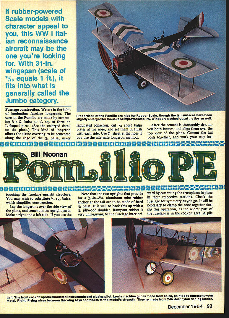
- Cockpit details: The left front cockpit has simulated instruments, a balsa pilot, and a Lewis machine gun made of balsa and painted to represent worn metal.
- Landing gear: The "crotch" of the V landing gear has an inverted U bent into it to allow spring-axle travel (on full-scale aircraft usually controlled by a bungee cord). Two 1/8-in.-dia. axles are used, one soldered into the bottom of the V and the second soldered at the axle center. Bind the landing-gear wire to the fuselage crosspieces with light thread before applying cement. Wire legs may be faired with oval-section plastic straws or appropriately sized balsa. A straw sheath can cover the axle assembly. Wheels can be turned from balsa or purchased ready-made.
- Cabane strut unit: Bent from 1/32-in. wire, the right and left parts are soldered at the apex. An airfoil-shaped center section (patterned from 1/16-in. balsa) is epoxied in place; this unit is made from two pieces of 1/16-in. plywood and a 1/8-in. sheet balsa center. Drill it to allow passage of the top wing-root indexing pins that insert into tubes in the wings. After painting, the cabane unit "plugs in" to the fuselage tubes.
Wing construction
- General: Removable wing bays were incorporated to ease transit and reduce damage from impacts. Construction follows conventional practice.
- Ribs and spars:
- Ribs are cut from medium 1/16-in. sheet balsa, except root ribs, which are 3/32 in.
- Notch spar positions with a small file to avoid splitting ribs.
- Lightening holes were made with a common notebook punch (optional — this may split some ribs).
- Assembly:
- Pin spars in position over the plans (do not pierce the wood), elevating them slightly to allow undercamber.
- Cement ribs at their stations, checking for perpendicularity.
- Cement the leading edge (LE) and notched trailing edge (TE) in place.
- Wing tips: Make tips by bending two pieces of 1/8 x 1/8-in. basswood around a waxed cardboard form. Soak the basswood in hot water with a little household ammonia (not detergent) to facilitate bending; rinse thoroughly before applying white glue. Allow to dry on the form overnight, then trim and fair into the LE and TE. Cut and sand LE and TE to the proper airfoil.
- Simulated ailerons: Add a 1/8 x 1/8-in. balsa strip bridging the last three ribs on the top wing as a simulated aileron base for a dummy control horn.
- Strut bases: Add 1/16-in. sheet balsa strut bases between the ribs, contour to the airfoil, then drill to receive strut stubs.
- Removable wing bay retention: Wing bays are held with small orthodontist rubber-bands stretched between 0.015-in. wire hooks cemented on the underside of the top and bottom leading and trailing edges at the wing roots.
- Wing indexing: Bamboo or 3/32-in. O.D. aluminum pipes (about 3/16 in. long) act as indexing pins to align the wings to the fuselage and cabane section. Fit these into aluminum tubing in the fuselage and wings. Assemble the wings with the correct dihedral in a temporary jig, epoxy the wing-root tubing with the index pin in place, and allow to dry before disassembling.
- Interplane struts: May be made from flattened plastic straws or cut from balsa. For the straw method, insert bamboo slivers about 1 in. long at each end of the strut, allowing 1/4 in. to protrude; glue the slivers, then steam and bend the straw around them. Alternatively, insert short pieces of aluminum tubing into the strut ends and cement strut attachments to wings and fuselage.
- Flying wires: Add flying wires between wing bays for strength; use 2-lb.-test nylon fishing leader.
Tail assembly
- Construction method: Both horizontal and vertical stabilizers are built by the "sprung rib" method for a symmetrical, lightweight surface.
- Procedure:
- Bend outlines from laminated basswood like the wing tips.
- Position finished outlines over the plans.
- Cut trailing edges from 1/16-in. sheet balsa and cement in place.
- Cut rib "bottoms" from 1/8 x 3/16-in. strip balsa and cement between leading and trailing edges.
- Cut spars and cement them on top of the 3/32-in.-width ribs.
- Cut duplicate rib "tops," cementing at the leading edge.
- Gently lift the bottom unit while bending the top ribs to fair in with the trailing edge; cement ribs at spars and trailing edges.
- Trim and sand leading and trailing edges.
- Fill the center section of the horizontal stab (both top and bottom) with 1/32-in. sheet balsa.
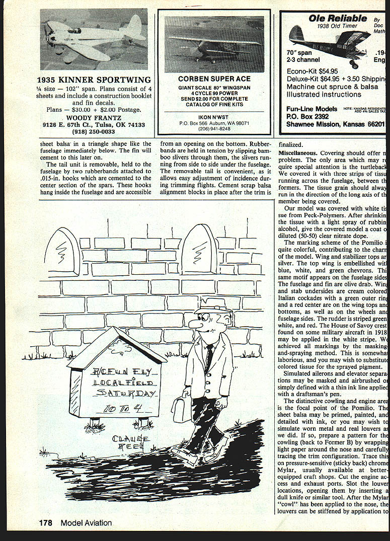
- Removable tail: The tail unit is removable, held to the fuselage by two rubber bands attached to 0.015-in. hooks cemented to the spars' center section. These hooks hang inside the fuselage and are accessible from an opening on the bottom. Rubber bands are held in tension with bamboo slivers running side to side under the fuselage.
- Adjustment: The removable tail allows easy incidence adjustment during trimming flights. Cement scrap balsa alignment blocks in place after trimming is finalized.
- Rudder: The rudder fits into the holes in the strut bases in final assembly.
Covering, finishing and markings
- Covering: Cover the model with tissue, observing that the tissue grain runs along the long axis of the member being covered. The turtleback may require special attention; cover it with three strips of tissue running across the fuselage between the formers.
- Doping and sealing: After shrinking the tissue with a light spray of rubbing alcohol, give the model a coat of diluted (50–50) clear nitrate dope.
- Color scheme:
- Tops of wings and stabilizer: silver.
- Top wing: blue, white, and green chevrons.
- Fuselage sides: repeat the chevron motif; fuselage and fin in olive drab.
- Undersides of wings and stabilizer: cream.
- Italian cockades (green outer ring, red center) on wing tops and bottoms, wheels, and fuselage sides.
- Rudder: green, white, and red stripes; optionally add the House of Savoy crest in the white stripe (found on some 1918 military aircraft).
- Markings achieved by masking-and-spraying; colored tissue may be substituted for sprayed pigment.
- Surface details: Simulated aileron and elevator separations may be masked and airbrushed or defined with a thin ink line using a draftsman’s pen.
- Cowling and engine detailing:
- Prime and paint sheet balsa or simulate worn metal and louvers.
- To simulate louvers, prepare a pattern for the cowling (back to Former B) by wrapping light paper around the nose and tracing the trim. Transfer to pressure-sensitive chrome Mylar, cut engine-access and exhaust ports, and slot louver locations. Open louvers by inserting a dull knife. Apply the Mylar cowl to the nose; stiffen louvers with cement along inside edges. Cover the nose with pressure-sensitive metallic Mylar painted flat gray; normal handling produces paint wear at louver edges for a realistic look.
Flight trimming and handling
- Balance: Because of generous wing area, balancing is critical. At least 1 oz of ballast is usually required; never use less. Balance the model with the rubber motor in place.
- Incidence: It may be necessary to adjust longitudinal incidence while trimming. The original model tended to stall until the stab had about a 1/2-in. shim under the leading edge and balance matched the plans. Final adjustments will vary; use the removable tail to set incidence during trimming flights.
- Flight characteristics: With proper trim the model is stable in flight and tends to fly in left-hand circles on takeoff and initial flights.
- Rubber motor: The assembly will tolerate about 1,100 turns if properly lubricated and within safety margins.
Notes and suggestions
- The Pomilio PE makes an attractive rubber-powered scale model with good character and appeal for WW I Italian reconnaissance aircraft enthusiasts.
- The removable wings and tail simplify transit, storage, and trimming.
- Use care with internal fittings and reinforcements where the rubber motor and anchors are located.
Good luck.
Transcribed from original scans by AI. Minor OCR errors may remain.

